Sebastian AndreasMerkt1,∗,Riccardo MariaBianchi1,JosephBoudreau1,Paul
Gessinger-Befurt2,4,EdwardMoyse3,AndreasSalzburger4, andVakhtangTsulaia5
on behalf of the ATLAS Collaboration
1University of Pittsburgh,US
2Institut für Physik, Universität Mainz,DE 3University of Massachusetts, Amherst,US
4European Laboratory for Particle Physics, CERN,CH 5Lawrence Berkeley National Laboratory, Berkeley,US
Abstract.Until recently, the direct visualization of the complete ATLAS exper-iment geometry and physics objects was confined within the software frame-work of the experiment. To provide a detailed interactive data visualization capability to users, as well as easy access to geometry data, and to ensure plat-form independence and portability, great effort has been recently put into the
modernization of both the core kernel of the detector description and the visu-alization tools. In this proceedings we will present the new tools, as well as the lessons learned while modernizing the experiment’s code for an efficient use of
the detector description and for user-friendly data visualization.
1 Introduction
In ATLAS [1], as in most other High Energy Physics experiments, a detailed and accurate detector geometry description as well as interactive visualization is needed for a number of different tasks. These tasks range from detector development, to the validation of the
algo-rithms used for reconstruction of the physics objects from measurements, from the validation of simulations to the documentation of physics results and presentation of discoveries.
The ATLAS detector geometry is described by shapes and classes from the GeoModel [2] toolkit, a C++library of geometrical primitives. The geometry is currently built on the fly
from the C++code upon request. For the visualization of the geometry and the physics
objects, ATLAS uses the general-purpose 3D visualization tool VP1 [3, 4]. Its integration in the experiment’s offline software framework Athena [5] makes it possible to access all
possible data from the experiment, but also limits its usage. The goal of this proceedings is to present recent developments towards standalone and experiment-agnostic software libraries and applications, to be used in HEP experiments. In particular, a new standalone GeoModel toolkit, and a new standalone, lightweight event display, called VP1-Light.
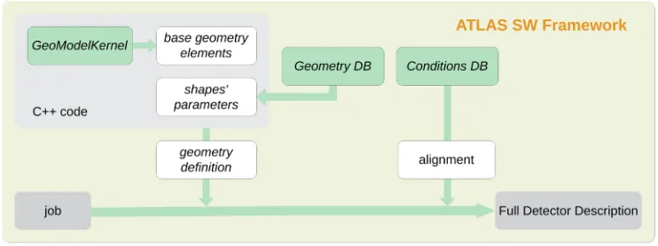
Figure 1.The workflow describing how the Detector Description is currently built in ATLAS. At first, in the C++code, the basic geometry description is built as a hierarchical tree using the basic geometrical shapes from the GeoModel kernel library and the shape parameters from the GeometryDB; then, the alignment parameters taken from the Conditions DB are applied, to obtain the full Detector Description. Currently, the whole workflow needs to be performed within the experiment’s software framework.
2 ATLAS detector geometry description and visualization
2.1 Current implementation of the ATLAS Detector DescriptionATLAS software uses the GeoModel toolkit for building transient representation of the de-tector geometry at run time. The main purpose of GeoModel is to provide identical dede-tector description information to various applications (e.g. detector simulation, data reconstruc-tion). GeoModel provides a scheme for accessing both the raw geometry of a detector and arbitrary subsystem-specific geometrical services (readout geometry) on top of the raw ge-ometry, while incorporating time-dependent alignment corrections.
ATLAS GeoModel-based applications build the description of detector geometry by read-ing input parameters (primary numbers) from the ATLAS Geometry Database [6], see Fig-ure 1. The relational schema of the Geometry Database allows versioning of primary num-bers. As a consequence, ATLAS GeoModel descriptions are also versioned. The users can request building of a specific version of the ATLAS geometry description by providing single input parameter to the application - an ATLAS Geometry Tag.
The GeoModel toolkit and the Geometry Database have served ATLAS well for almost 15 years. However, the current implementation has several important drawbacks:
• The GeoModel kernel library is currently part of the ATLAS offline software release, which makes it very difficult to use this library in standalone applications.
• The absence of persistification mechanisms for GeoModel, makes it impossible to share the geometry description with applications outside of the Athena framework
We have recently addressed these issues by extracting the GeoModel kernel from the Athena codebase and making it a standalone library.
2.2 Accessing and visualizing experimental data
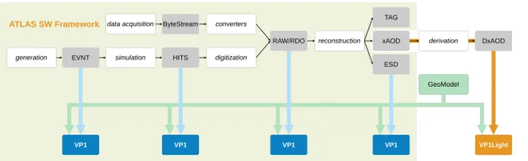
Experimental data collected by the ATLAS detector are processed in multiple steps (see Fig-ure 2): from raw detector measFig-urements to data usable for physics analysis, data are filtered, reconstructed, and processed through a long chain of tools and data formats. All these steps
because data analysis and visualization of the same data file had to be run on two different platforms.
We have recently addressed this issue by developing a lightweight version of VP1, VP1-Light. This is based on the new standalone GeoModel toolkit (see Section 3) and it can be used to open, browse, and visualize xAOD data without the framework, on any platform. Further details on VP1-Light and VP1 are given in Section 6.
Figure 2. Data collected or generated by ATLAS are processed and filtered through different steps. All steps are performed within the experiment’s software framework, the build of the GeoModel-based ATLAS geometry as well as the visualization of the data (through VP1[3]).
3 Standalone GeoModel
In order to facilitate the usage of GeoModel in applications outside of the Athena framework, we have extracted the GeoModel kernel from the code of the ATLAS software framework, Athena. This was a relatively simple task, given the GeoModel kernel has no dependen-cies on other ATLAS software components. At the same time we dropped the only external dependency of the GeoModel kernel, CLHEP [9], and switched to Eigen [10].
ATLAS Geometry Database access code is tightly integrated into the Athena framework. As a result, it is highly non-trivial to build the ATLAS GeoModel-based detector description in standalone applications exactly the same way it is being done within Athena. A some-what more straightforward approach is to rely on a persistent representation of the ATLAS GeoModel description, which can be generated within Athena and then used as input for standalone applications. This is further discussed in Section 4.
Figure 3.The architecture of the persistification mechanism of the GeoModel-based detector descrip-tion. On the left side, the packages responsible for the dump of the detector description (DumpGeoand
GeoWrite; on the right, those responsible of the loading (GeoRead); at the center, on the top, the Geo-ModelDBManagerpackage, with its interface class and two implementations, one based on SQLite and one based on JSON. On the bottom, a test package for the export to a Neo4j [15] graph database [14].
ATLAS Simulation and Reconstruction applications which run within Athena. However, for standalone use-cases (e.g. detector development, event display) such an accurate geometry description is not required. As a result, the inability to apply time-dependent geometrical alignments in standalone applications is not considered an issue.
4 GeoModel Persistification
As discussed earlier, the geometry of the ATLAS detector is currently built on the fly based on its description in C++code. This is an issue for standalone applications running outside the experiment’s framework, because they cannot access the detector description. After making GeoModel a standalone library, it was possible to solve this issue by designing and developing a new mechanism [11] to get a persistent copy of the detector geometry; Figure 3 shows a diagram of its current architecture. The mechanism implements a writing part, storing geometry information to file, and a loading part, restoring the detector description from file.
The writing part uses an AthenaAlgorithmcomponent (DumpGeoin the figure), which has to be run inside the framework, to load from the framework the geometry description from C++code and the details related to a givengeometry tagfrom the GeometryDB, and to build it on the fly. Then, the algorithm calls the GeoWritelibrary, which implements a GeoModelaction: a routine which traverses the geometry tree, saving the details of each node traversed (shape’s parameters, materials, space transformations, and so forth) and the parent-child relationships between the nodes. The data are then serialized through the usage of theGeoModelDBManagerinterface, which stores the data in an output file according to the interface chosen.
Figure 3.The architecture of the persistification mechanism of the GeoModel-based detector descrip-tion. On the left side, the packages responsible for the dump of the detector description (DumpGeoand
GeoWrite; on the right, those responsible of the loading (GeoRead); at the center, on the top, the Geo-ModelDBManagerpackage, with its interface class and two implementations, one based on SQLite and one based on JSON. On the bottom, a test package for the export to a Neo4j [15] graph database [14].
ATLAS Simulation and Reconstruction applications which run within Athena. However, for standalone use-cases (e.g. detector development, event display) such an accurate geometry description is not required. As a result, the inability to apply time-dependent geometrical alignments in standalone applications is not considered an issue.
4 GeoModel Persistification
As discussed earlier, the geometry of the ATLAS detector is currently built on the fly based on its description in C++code. This is an issue for standalone applications running outside the experiment’s framework, because they cannot access the detector description. After making GeoModel a standalone library, it was possible to solve this issue by designing and developing a new mechanism [11] to get a persistent copy of the detector geometry; Figure 3 shows a diagram of its current architecture. The mechanism implements a writing part, storing geometry information to file, and a loading part, restoring the detector description from file.
The writing part uses an AthenaAlgorithmcomponent (DumpGeoin the figure), which has to be run inside the framework, to load from the framework the geometry description from C++code and the details related to a givengeometry tagfrom the GeometryDB, and to build it on the fly. Then, the algorithm calls the GeoWritelibrary, which implements a GeoModelaction: a routine which traverses the geometry tree, saving the details of each node traversed (shape’s parameters, materials, space transformations, and so forth) and the parent-child relationships between the nodes. The data are then serialized through the usage of theGeoModelDBManager interface, which stores the data in an output file according to the interface chosen.
At the time of writing, two interfaces have been implemented: one based on the SQLite [12] self-contained database, and whose data model has been optimized for size and compactness (more details in [11]), and a new one, based on the JSON [13] data-interchange format, more verbose but human-readable and designed for manual interaction with the ge-ometry configuration. To load the persistent copy of the gege-ometry, theGeoReadpackage is used, which makes use of the same interface package,GeoModelDBManager, to handle the correct database format.
logical volumes, materials, shapes, and so forth. Of those objects, only the parameters needed by the corresponding constructors are stored, plus several parameters used to customize the shape. The GeoModel library allows the use of referenced nodes: when an object uses another GeoModel object (like logical volumes, which need a shape node and a material node to be created), only the database identification number of the latter is stored in the parameters list of the former. Shared nodes, that is GeoModel objects which are used by multiple objects within the tree, are stored only once. Auxiliary tables store metadata related to the nodes and to the geometry tree, as the parent-child relationships among the nodes. More details on the SQLite data format can be found in [11].
4.2 Geometry JSON data format
The SQLite-based data format is compact and optimal to be used as data-interchange format but it is difficult to query, to read, and to manipulate by hand. Moreover, it is not easy to split the geometry among multiple files. To address these issues and to let end users interact with the geometry configuration directly, we recently designed and developed a new data model based on JSON.
The JSON data model is based on two main parts: anodessection, which stores the details of the GeoModel entities used in the geometry tree, and atreesection, which stores the details about the parent-child relationships among the nodes. Shared and referenced objects are identified by their identification number and stored only once, as in the SQLite data format.
One of the big advantages of the JSON file is the ability for the end user to explore and edit the geometry configuration directly. Moreover, the geometry description can be split over multiple files: for example, a file can store the geometry of a particular sub-system or sub-detector. This eases the development and the maintenance of the geometry description by different groups.
5 Experiment-agnostic geometry library for HEP
The recent developments described in Sections 3 and 4 let us package the ATLAS geometry library into an experiment-agnostic toolkit, which can be used by other experiments.
Figure 4.An updated view of the flow chart shown in Figure 2, reflecting the most recent developments presented in this proceedings. Here, VP1-Light accesses xAOD and DxAOD files in standalone mode, while taking the geometry information from the persistent copy from the new standalone GeoModel packages, without the need for the experiment’s software framework.
features like export to standard, non-HEP data exchange formats such as SQLite and JSON. In particular, the latter could be further exploited in future developments of common visual-ization tools, following the new guidelines of the HEP Software Foundation [17, 18].
6 Standalone visualization: VP1-Light
As discussed in Section 2.2, the ATLAS 3D event display VP1 is tightly integrated in the experiment’s offline software framework Athena to access all kinds of experimental data. However, this tight integration puts limits when visualizing the geometry and developing or modernizing its code.
VP1 can only be used on platforms supported by the ATLAS software framework’s code1.
Many end-users do not have these platforms installed on their personal computers and can therefore not run VP1 locally. They have to run VP1 either remotely or in a virtual machine. This comes with several drawbacks. The performance can be slow over the network when run remotely, since a lot of 3D data is sent back and forth. For VP1 in a virtual machine not all graphics options are available since the 3D rendering is done on the software rather than the hardware side; consequently, the quality of the resulting images is not as high as it could be if VP1 were to be run natively. Another disadvantage of the integration of VP1 into Athena is the complex run time dependency that VP1 inherits from Athena. This makes the initialization of VP1 a lengthy process, taking several minutes and significantly slowing down the start-up of VP1. All of this makes VP1 a cumbersome tool for physics analysis users but also developers. The new VP1-Light has been developed to address these issues.
Users who primarily run data analysis jobs on their custom filtered event data on their personal computers, would benefit from being able to run the data visualization application VP1 on the same platform. The data used for physics analyses are usually stored in xAOD files, in a ROOT format, which does not require full access to the ATLAS Athena framework. For this purpose, and leveraging the use of the new experiment-agnostic GeoModel library and of the standalone detector description persistification mechanism, the development of a standalone, lightweight version of VP1, called VP1-Light, has recently begun. Figure 4 shows an updated version of the drawing shown in Figure 2, illustrating the recent develop-ments: the GeoModel toolkit is now a standalone library. Moreover, VP1-Light is able to get
1At the time of writing, the ATLAS software framework can be fully compiled only on Scientific Linux 6 (SLC6) and CERN Centos7 (CC7), CERN-customized versions of RedHat Linux 6 and Centos7, respectively.
Figure 5. The VP1-Light user interface on macOS, showing the main window and the 3D view on the background and two pop-up win-dows which let users adjust various settings (geometry visualization, on the left; global set-tings, on the right).
Figure 6. A view of the VP1-Light 3D window displaying reconstructed physics ob-jects (calorimeter clusters and inner detector tracks) on top of parts of the inner detector and calorimeter geometry.
the geometry data from the persistent geometry database, while taking the physics data from the xAOD and the DxAOD files. VP1 will continue to be able to open xAOD/DxAOD files.
VP1-Light runs upon a customized subset of ATLAS Athena packages, but it is inde-pendent of Athena itself and can be run on a personal computer or laptop. It is a cross-platform application and is supported for both Linux and macOS, two widely used cross-platforms for ATLAS physics analysis users. Figure 5 shows VP1-Light running on macOS. Further-more, VP1-Light will be distributed as an application bundle for Ubuntu Linux and macOS. These bundles include the VP1-Light binaries as well as all the required dependencies such as ROOT and Qt5. This allows users to run VP1-Light out of the box without the need for lengthy compilation procedures. Instead, users will get a mountable volume, such as an AppImage [19] for Linux or an Apple Disk Image for macOS.
software releases. One promising candidate is Qt 3D [21] which is now available as a stable version. Further investigation needs to be done to ensure it fulfills all requirements.
7 Conclusions
So far, in ATLAS, access to the detailed detector description was tightly embedded into the experiment’s software framework, preventing the access to the geometry information and the visualization of both the detector geometry and physics data on platforms other than those supported by the framework. This affected end users, as well as application developers.
The new developments presented in this proceedings addressed these issues, letting ap-plication developers rely on a new experiment-agnostic, standalone geometry library and end users use a standalone, platform-independent event display.
Foreseen future developments include standalone converters from the persistent detector description to Geant4 formats, in order to let users use the ATLAS geometry and VP1-Light in simulation development, without the need of running the entire experiment’s framework.
Furthermore, to leverage the work presented here, the libraries and the mechanisms will be further extended in order to be shared as experiment-independent tools for the HEP com-munity to freely use them. This will be the subject of a different report.
References
[1] ATLAS Collaboration, The ATLAS Experiment at the CERN Large Hadron Collider, JINST 3 (2008) S08003.
[2] J. Boudreau, V. Tsulaia, CHEP 2004 Book of Abstracts (2004) [3] T. Kittelmannet al, J. Phys.Conf. Ser. 219032012 (2010),
VP1 website: https://cern.ch/atlas-vp1 [accessed 2019-03-12]
[4] R. M. Bianchiet al, J. Phys.Conf. Ser. 898072014 (2017) [5] G. Duckecket al, CERN-LHCC-2005-022 (2005)
[6] J. Boudreau, V. Tsulaia, R. Hawkings, A. Valassi, A. Schaffer, CHEP 2006 (2006)
[7] A. Buckley et al, J. Phys.: Conf. Ser.664, 072045 (2015)
[8] R. Brun, F. Rademakers, Nucl. Inst. & Meth. in Phys. Res. A389, 81-86 (1997) [9] CLHEP, http://proj-clhep.web.cern.ch/proj-clhep [accessed 2019-03-12]
[10] Eigen, eigen.tuxfamily.org/index.php [accessed 2019-03-12]
[11] R. M. Bianchiet al, J. Phys.Conf. Ser. 898072015 (2017)
[12] SQLite (self-contained database), https://www.sqlite.org/index.html
[accessed 2019-03-12]
[13] JSON (data-interchange format), https://www.json.org [accessed 2019-03-12]
[14] R.M. Bianchi, I. Vukotic, A scalable new mechanism to store and serve the ATLAS detector description through a REST web API, (submitted),
https://cds.cern.ch/record/2290833 [accessed 2019-03-12]
[15] Neo4j[Computer software], https://github.com/neo4j/neo4j [accessed 2019-03-12]
[16] DD4hep, https://dd4hep.web.cern.ch [accessed 2019-03-12]
[17] HSF,A Roadmap for HEP Software and Computing RD for the 2020s, https://arxiv.org/abs/1712.06982 [accessed 2019-03-12]
[18] HSF,HEP Software Foundation Community White Paper Working Group – Visualiza-tion, (forthcoming)
[19] AppImage, https://appimage.org [accessed 2019-03-12]
[20] Coin3D Toolkit, https://bitbucket.org/Coin3D/coin/wiki/Home [accessed 2019-03-12]
![Figure 2. Data collected or generated by ATLAS are processed and filtered through different steps.All steps are performed within the experiment’s software framework, the build of the GeoModel-basedATLAS geometry as well as the visualization of the data (through VP1[3]).](https://thumb-us.123doks.com/thumbv2/123dok_us/7996859.1327952/3.482.59.426.287.398/collected-generated-processed-ltered-dierent-experiment-basedatlas-visualization.webp)