Analysis of Multi-Band Circle MIMO Antenna Design for C-Band
Applications
Kommana Vasu Babu1, * and Bhuma Anuradha2
Abstract—In this paper a novel design to reduce mutual coupling in circular patch antennas is proposed. A circular MIMO antenna with a dumb-bell shape parasitic element is inserted between the two circular patch antennas thereby reducing the mutual coupling. It has been observed that the proposed design produces multi-band characteristics at 3.1 GHz, 6.2 GHz & 7.7 GHz. At the tri-band frequencies impedance bandwidths (IBW’s) are around 90 MHz, 320 MHz, and 540 MHz. The process involves cutting rectangular slits on each side of a circular patch and placing a dumb-bell shaped parasitic structure to reduce the transmission coefficient (S12) to −40.75 dB. It is observed that the antenna parameters are greatly improved in terms of ECC, diversity gain, directivity, group delay, and peak gain which are are 0.005, 9.973 dBi, 6.14 dBi, 10.81±1 nsec, and 3.59 dBi. The results of experimental validation and numerical analysis are presented. The antenna design can be used for wireless communication as well as all C-band applications.
1. INTRODUCTION
In wireless communication technology, a number of new developments have led to improved wideband characteristics, improvement in isolation, good polarization diversity, orthogonality performance, and design of simple structures. These structures support WiMAX (5.48–5.74 GHz), UWB ranges (3.1– 10.3 GHz), ITS (5.84–5.92 GHz) for single platform vehicular communication, and WLAN (5.14– 5.34 GHz & 5.72–5.82 GHz). Various dual/tri-feed/quad feed/multi and single band antennas have been observed [1–25]. Planar UWB easily extendable array antenna is operated at a frequency 3.1– 16.0 GHz producing a gain of 4 dBi, and ECC is 0.025 with an occupied area of 38×90 mm2 [1]. By using split-ring resonator (SRR) polarized MIMO analysis shows a low ECC around 0.001 while with a compact antenna area 40.5 mm ×40.5 mm [2], S12 is greater than −20 dB. In [3], a slot antenna for diversity applications has producedS12 of−21 dB operating between 2.8 and 11.0 GHz. Minkowski MIMO has multi-band frequencies [4] reducing isolation greatly to−52 dB with cutting rectangular slots on an around patch MINI antenna. A novel printed filtenna with a dimension of 35×68 mm2 produced a dual-band of frequencies which maintain an isolation≤ −20 dB with a peak gain≥3.5 dBi in [5] and identify better out-band characteristics at the resonant frequencies. For mobile terminal applications, using a G-shaped slot [6] on the radiator results in a peak gain 4.78 dBi, ECC maintained less than 0.04, and occupied area 4100 mm2. In [7], star, H, circular, I, and square shape EBG structures were identified which increased the gain, improvedS11, reduced isolation with compact dimensions of 35 mm×40 mm. A compact stepped slot UWB design of 44 ×44 mm2 had an ECC 0.04, peak gain 3.8 dBi, and a mutual coupling value less than −15 dB [8] by suppression of common-mode. In [9], a UWB MIMO design had a size of 60×48 mm2 and produced dual-band antenna with a band-notched function. An inverted F-shape antenna, square ring dual-polarized for radar, UWB & imaging applications has
Received 11 December 2018, Accepted 8 February 2019, Scheduled 27 March 2019
* Corresponding author: Kommana Vasu Babu ([email protected]).
1 Department of Electronics & Communication Engineering, Vasireddy Venkatadri Institute of Technology, Nambur, Guntur, A.P,
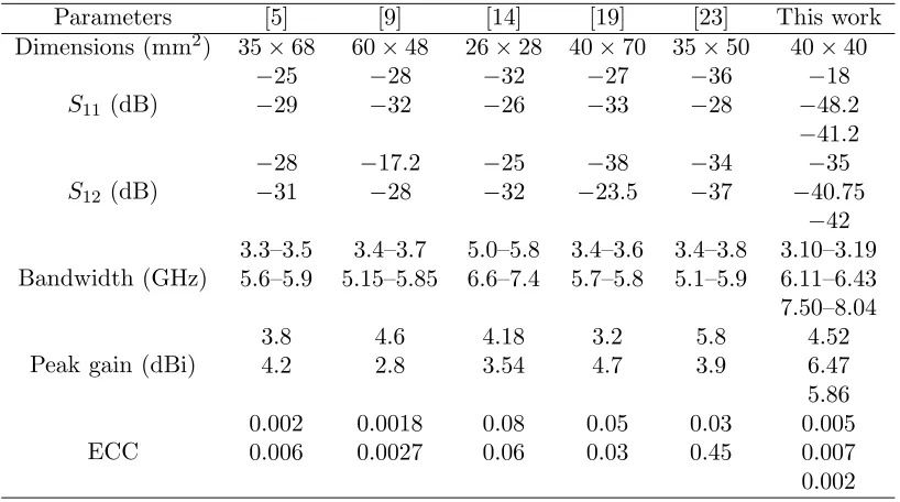
been proposed, and using black film carbon technology [10–12] has resulted in suppressing the mutual coupling. To enhance wider-band isolation [13], a tree structure with small size of 35×40 mm2 covering 3.1–10.6 GHz hasS12<−20 dB. A Dual Band Notched [14] MIMO diversity radiator for UWB wireless system applications maintained an ECC value ≤0.08 was observed. A loop antenna had a meandered structure using [15, 16] WLAN and LTE operated 1760–2630 MHz & 675–1098 MHz and integrated DGS for patch antenna. A packed antennas having 20×40×1.6 mm3with center-to-center distance 0.05λ0was designed to enhance isolation [17]. A tri-band notched MIMO had a transmission coefficient−39 dB and reflection coefficient −41 dB and an overall occupied area of 3136 mm2 [18]. A dual inverted F-shaped dual-band antenna had a size of 74 mm×150 mm, decoupled building block [19] of eight antennas of dual-band 3.5/5.8-GHz MIMO radiator for smart phone application. A compact co-planar waveguide (CPW) fed hexagonal ring antenna having monopole elements [20] with ground plane was connected operating from 3.0 to 12.0 GHz with ECC ≤ 0.18 and S12 ≤ −15 dB. In [21], a 27.2×46 mm2 UWB MIMO antenna exhibites a number of stopbands using a compact radiator; efficiency varies from 78 to 96.7%; peak gain varies from 1.4 dBi to 4 dBi; ECC is 0.018; DG was approximately 10 dB. A CSRR UWB diversity antenna [22] operating from 3 to 12 GHz has an efficiency of 82%, and gain value is 4.7 dBi, and ECC < 0.15 with a compact size 23 mm×29 mm. In [23], it is observed that the performance evaluation of 5G communication having dual-mode & triple-band MIMO 10-antenna handset array antenna maintains ECC≤0.05. A triband MIMO antenna [24] has a size of 40×35 mm2 for WiMAX, radio astronomy and WLAN applications with reduced isolation (S12) around −52 dB. In [25], a compact multi-band MIMO radiator improved the isolation parameter greatly. In this research paper, an interesting observation has been made that a radiator having a total area of 40 mm×40 mm2 was greatly improved with S11 of −46.8 dB, S12 of −40.75 dB, operating range of frequencies from 2.0 to 10.0 GHz, a peak gain of 4.16 dBi, and ECC as low as 0.005. Table 1 shows the parameters of the proposed radiator compared with the previously existed systems.
Table 1. Comparison with other existing works.
Parameters [5] [9] [14] [19] [23] This work Dimensions (mm2) 35×68 60×48 26×28 40×70 35×50 40×40
S11 (dB)
−25 −28 −32 −27 −36 −18 −29 −32 −26 −33 −28 −48.2
−41.2
S12 (dB)
−28 −17.2 −25 −38 −34 −35 −31 −28 −32 −23.5 −37 −40.75
−42
Bandwidth (GHz)
3.3–3.5 3.4–3.7 5.0–5.8 3.4–3.6 3.4–3.8 3.10–3.19 5.6–5.9 5.15–5.85 6.6–7.4 5.7–5.8 5.1–5.9 6.11–6.43 7.50–8.04
Peak gain (dBi)
3.8 4.6 4.18 3.2 5.8 4.52
4.2 2.8 3.54 4.7 3.9 6.47
5.86
ECC
0.002 0.0018 0.08 0.05 0.03 0.005 0.006 0.0027 0.06 0.03 0.45 0.007 0.002
2. ANTENNA DESIGN
(a) (b)
Figure 1. Circle MIMO antenna design representation. (a) Circle MIMO antenna design. (b) Fabricated design.
Table 2. Circle MIMO antenna design with parasitic structure dimensions.
Design parameter L W a b c d e f g h i εr Value (mm) 40 40 24 2 3 5 2 2 10 3 10 4.4
MIMO approach DMS in circular patches and inserting a dumbbell-shaped slot between the patches reduces the mutual coupling greatly. This approach results in three resonating bands 3.10–3.19 GHz (Wireless communication), 6.11–6.43 GHz & 7.50–8.04 GHz (C-band applications). The antenna has a compact size of 40 mm×40 mm with 1.6 mm as the thickness of substrate. FIT based technique is used for investigation of parametric study of the proposed system, and a 50 Ω MS line is used for excitation. The optimized dimensions of proposed system are listed in Table 2. By choosing proper dimensions of MIMO antenna design, the EM interaction between the patches is reduced to required level, thereby improving the performance parameters.
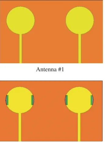
Different stages of the evaluation of the proposed structure are shown in Fig. 2. Antenna #1
Antenna #1 Antenna #2
Antenna #5
Figure 2. Circle MIMO antenna design evaluation stages.
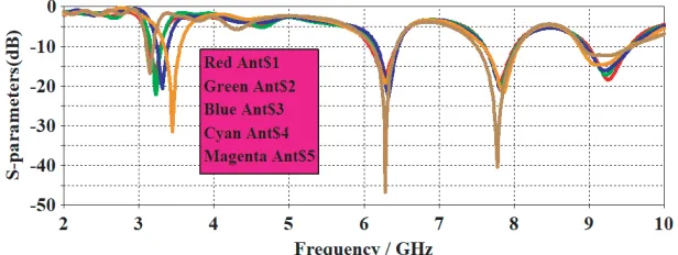
Figure 3. S11of step by step antenna process.
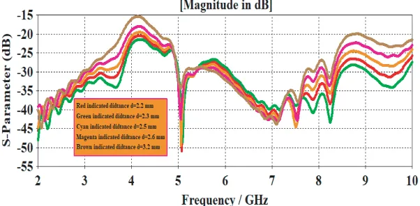
Figure 4. S11parametric analysis for different distance variations.
Figure 5. S12parametric analysis for different distance variations.
observes that there is a little bit variations inS11 and changes inS12for different mentioned distances varied at the three resonate bands of frequencies−30 dB to−60 dB. A particular separation distance of d= 2 mm between the radiating patches produced around−48 dB greatly minimizes the EM interaction between the patches. In this case, the antenna radiates efficiently, and investigation of analysis pattern at different frequency components minimizes the mutual coupling when the two antennas are close to each other.
3. THEORETICAL ANALYSIS
The width (W) of MSPA is evaluated from
W = c
2fr
εr+ 1 2
(1)
where
fr= resonant frequency c= Velocity of light
εr = Substrate dielectric constant
The length (L) of MSPA is evaluated from
L= λ0
2fr√εreff −2ΔL (2)
where
εeff = substrate effective dielectric constant λ0 = free space wavelength
ΔL= increase in length.
ΔL= 0.412h
⎡ ⎢ ⎢ ⎣
(εreff + 0.3)
W
h + 0.264
(εreff −0.258)
W h + 0.8
⎤ ⎥ ⎥ ⎦ (3) Here
h= substrate height
εreff = εr+ 1 2 +
εr−1 2
1 + 12 h W
−1 2
(4)
Effective length of the antenna is given by
L=Leff + 2ΔL (5)
4. RESULT ANALYSIS DISCUSSION
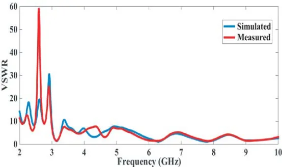
The simulated and experimentally verified results are as shown in Fig. 6. The simulated isolation is greater than−10 dB for the entire operating band. Our proposed design has a tri-band antenna: 3.10– 3.19, 6.11–6.43 & 7.50–8.04 GHz covering the wireless communication and C-band applications. The observations in Fig. 7 reveal a slight variation in the three resonating bands of frequencies between measured and experimental VSWRs. The first frequency resonates at 3.1 GHz. It is observed that the measured band is also resonant at the same frequency, but the value decreases at approximately −12.45 dB. The second band resonates at 6.2 GHz, and it is observed that the measured frequency slightly shifted to left side of simulated frequency, a little bit variations at 6.1 GHz. This happens because variation inS11 of−25 dB is observed in alignment measurement in soldering of SMA connector. The final resonant band is at 7.7 GHz, and it is observed that the measured result has a small variation at the frequency 7.8 GHz with aS11 of−22 dB. Another important parameter in the design of MIMO antenna
Figure 6. S-parameters comparison practical & simulation.
particular distance it is observed thatS12 is ≤ −15 dB. For the first resonating band of frequency, the simulated value is −35 dB, and measured value is −28 dB, in which a slight variation is observed. At the second resonant frequency it is observed that the simulated value is −39 dB, and measured value is −33 dB. Finally at the third resonant band of frequency, it is observed that the simulated value is
(a) (b)
(c) (d)
(e) (f)
−42 dB, and measured value is −34 dB. At three resonating bands of frequencies, the proposed circle MIMO dumbbell-shaped parasitic element greatly improves the reduction of mutual coupling compared to the other existing approaches mentioned earlier. From the VSWR comparison it is observed that a slight variation is noticed between practical and simulated VSWRs, which is less than or equal to 2 at three resonant band of frequencies as shown in Fig. 7.
The distributions of surface current nature at three resonant frequencies are identified in Figs. 8(a)– (f), respectively, with port #2 terminated with 50 ohms load and exciting port #1. From Fig. 8(a), it can be clearly observed how the surface wave propagates from antenna 1 to antenna 2 and that more current passes at the center of circular patch and minimum current in the parasitic structure. Here the introduction of a parasitic structure between the patches has reduced the density of current in antenna 2 compared to the MIMO antenna in the case without parasitic structure. In Fig. 8(b) it is observed that port #2 is excited and port #1 terminated with 50 ohm load. The distribution of electric filed inside the MIMO substrate is significantly reduced with parasitic structure, and the isolation behavior
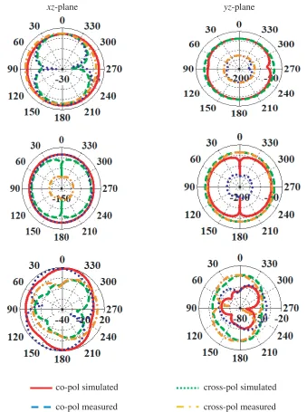
xz-plane yz-plane
co-pol simulated
co-pol measured
cross-pol simulated
cross-pol measured
Similarly from Figs. 8(d)–(f) it is observed that the distribution currents circulate inside the circular patches, and maximum current will flow inside the entire patch.
The three resonating bands have been indicated. Antenna 1 is excited and antenna 2 terminated, and vice versa. xzplane (E-plane) andyz-plane (H-plane) patterns of normalized radiations are shown in Fig. 9. The purpose of MIMO antenna is to achieve almost omnidirectional radiation pattern, and thus the signal is attained irrespective of the direction arrival with the help of its corresponding radiating antenna elements. It is observed that the xz-plane (E-plane) in Fig. 9 is preserved resulting in omnidirectional radiation pattern at three resonating frequencies. Co- and-cross polarizations show their behaviors of isolation in xz-plane (E-plane) except for limited points.
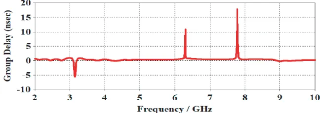
In Fig. 10 the real part of impedance S11 of circle MIMO parasitic element can be observed, and the imaginary part is also represented in Fig. 10. The real part of this design S11 of input impedance shows that the resonant peaks are at 3.1 GHz, 6.2 GHz, and 7.7 GHz in the frequency range from 2.0– 10.0 GHz represent a parallel circuit of RLC components connected in series. The simulated imaginary part impedance graph shows that it is inductive in nature, and more resistance value is around 50, showing a parallel behavior of RLC circuit in parallel. From Fig. 10 it is observed that a sharp peak of resistance observed at 6.2 GHz represents RLC circuit in parallel. The resonant band of circuit shows that two RLC parallel circuits are connected in series. Fig. 11 indicates the representation of group delay measured by keeping two identical antennas excited in the far-field distance which corresponds to the lowest frequency in the operating band side with side and face to face orientation. In both the cases it is observed that port #1 is excited and port #2 terminated with 50 ohms load, and vice versa.
Figure 10. Circle MIMO antenna impedance (Real & Imaginary) analysis.
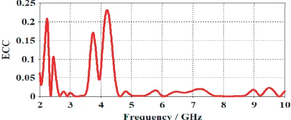
Figure 12. Circle MIMO ECC analysis.
From Fig. 11, it is observed that group delay is constant throughout the operating band except at three resonating frequencies which are 3.1 GHz, 6.2 GHz & 7.7 GHz. The group delay values at three resonant frequencies are observed as −5.3 nsec, 12 nsec and 18 nsec.
For any MIMO antenna, the performance of diversity is calculated using envelope correlation coefficient (ECC), diversity gain (DG), and figures-of-merit. For the isolated and correlated communication channels, the total occupied distribution volume is evaluated using ECC. For practical limitation uncorrelated antenna diversity is ECC<0.5, but ideally its value is zero. FromS-parameters the ECC for the first and second antennas is evaluated using Equation (6). The ECC of MIMO parasitic element is shown in Fig. 12, and this value becomes zero which represents good diversity. When the value of ECC reaches 0.24 at the lower resonating band, there is a decrease in the higher resonating band which is observed in MIMO antenna with parasitic design.
ECC(ρC) =
4π |S∗
11S21+S21∗ S22|
1−
|S11|2+|S21|2 1−
|S22|2+|S12|2
1/2
(6)
The diversity gain is almost closely related to the envelope correlation coefficient (ECC), and the lower the value of ECC is observed, the higher the value of DG is evaluated using the mathematical relation:
DG =
1− |ρc|2 (7)
The DG observed for MIMO parasitic element from Fig. 13 is near the maximum, almost equal to the 10 dBi, which resembles that better diversity performance.
7.7 GHz with a microstrip feeding has been proposed. The process involves cutting rectangular slots, inverted U-shape slots, and dumbbell-shape parasitic element inserted between the patches achieved to suppress the unpreventable mutual coupling. The proposed MIMO antenna has a wider impedance bandwidth withS11<−10 dB in three resonating bands of frequencies ranging from 2.0 to 10.0 GHz and has a reduced mutual coupling|S12|<−25 dB, which can be deduced from the measured and simulated results. It is interesting to observe that the antenna parameters are greatly improved in terms of ECC, diversity gain, directivity, group delay, and peak gain which are 0.005, 9.973 dBi, 6.14 dBi, 10.81±1 nsec, and 3.59 dBi, respectively.
REFERENCES
1. Sipal, D., M. P. Abegaonkar, and S. K. Koul, “Easily extendable compact planar UWB MIMO antenna array,”IEEE Antennas and Wireless Propagation Letters, Vol. 16, 2328–2331, 2017. 2. Irene, G. and A. Rajesh, “A dual-polarized UWB-MIMO antenna with IEEE 802.11 ac
band-notched characteristics using split-ring resonator,”Journal of Computational Electronics, 1–9, 2018. 3. Chacko, B. P., G. Augustin, and T. A. Denidni, “Uniplanar slot antenna for ultrawideband polarization-diversity applications,” IEEE Antennas and Wireless Propagation Letters, Vol. 12, 88–91, 2013.
4. Babu, K. V. and B. Anuradha, “Design of Multi-band Minkowski MIMO Antenna to reduce the mutual coupling,” Journal of King Saud University-Engineering Sciences, 2018.
5. Li, W. T., et al., “Novel printed filtenna with dual notches and good out-of-band characteristics for UWB-MIMO applications,” IEEE Microwave and Wireless Components Letters, Vol. 26, No. 10, 765–767, 2016.
6. Toktas, A., “G-shaped band-notched ultra-wideband MIMO antenna system for mobile terminals,”
IET Microwaves, Antennas &Propagation, Vol. 11, No. 5, 718–725, 2016.
7. Elsheakh, D. M. N., M. F. Iskander, E. A. Abdallah, H. A. Elsadek, and H. Elhenawy, “Microstrip array antenna with new 2D-electromagnetic band gap structure shapes to reduce harmonics and mutual coupling,” Progress In Electromagnetics Research C, Vol. 12, 203–213, 2010.
8. Liu, Y.-Y. and Z.-H. Tu, “Compact differential band-notched stepped-slot UWB-MIMO antenna with common-mode suppression,”IEEE Antennas and Wireless Propagation Letters, Vol. 16, 593– 596, 2017.
9. Tang, T.-C. and K.-H. Lin, “An ultra-wideband MIMO antenna with dual band-notched function,”
IEEE Antennas and Wireless Propagation Letters, Vol. 13, 1076–1079, 2014.
10. Lee, C.-H., S.-Y. Chen, and P. Hsu, “Integrated dual planar inverted-F antenna with enhanced isolation,” IEEE Antennas and Wireless Propagation Letters, Vol. 8, 963–965, 2009.
11. Krishna, R. V. S. Ram, and R. Kumar, “A dual-polarized square-ring slot antenna for UWB, imaging, and radar applications,”IEEE Antennas and Wireless Propagation Letters, Vol. 15, 195– 198, 2016.
12. Lin, G.-S., et al., “Isolation improvement in UWB MIMO antenna system using carbon black film,”
IEEE Antennas and Wireless Propagation Letters, Vol. 16, 222–225, 2017.
13. Zhang, S., et al., “Ultrawideband MIMO/diversity antennas with a tree-like structure to enhance wideband isolation,” IEEE Antennas and Wireless Propagation Letters, Vol. 8, 1279–1282, 2009. 14. Zhao, Y., F.-S. Zhang, L.-X. Cao, and D.-H. Li, “A compact dual band-notched MIMO diversity
antenna for UWB wireless applications,” Progress In Electromagnetics Research C, Vol. 89, 161– 169, 2019.
16. Chung, Y., et al., “High isolation dual-polarized patch antenna using integrated defected ground structure,” IEEE Microwave and Wireless Components Letters, Vol. 14, No. 1, 4–6, 2004.
17. Mak, A. C. K., C. R. Rowell, and R. D. Murch, “Isolation enhancement between two closely packed antennas,”IEEE Transactions on Antennas and Propagation, Vol. 56, No. 11, 3411–3419, 2008. 18. Li, J.-F., et al., “Compact dual band-notched UWB MIMO antenna with high isolation,” IEEE
Transactions on Antennas and Propagation, Vol. 61, No. 9, 4759–4766, 2013.
19. Wong, K.-L., B.-W. Lin, and B. W.-Y. Li, “Dual-band dual inverted-F/loop antennas as a compact decoupled building block for forming eight 3.5/5.8-GHz MIMO antennas in the future smartphone,”
Microwave and Optical Technology Letters, Vol. 59, No. 11, 2715–2721, 2017.
20. Mathur, R. and S. Dwari, “Compact CPW-fed ultrawideband MIMO antenna using hexagonal ring monopole antenna elements,” AEU — International Journal of Electronics and Communications, 2018.
21. Dabas, T., et al., “Mutual coupling reduction between elements of UWB MIMO antenna using small size uniplanar EBG exhibiting multiple stop bands,”AEU — International Journal of Electronics and Communications, 2018.
22. Khan, M. S., et al., “A compact CSRR-enabled UWB diversity antenna,” IEEE Antennas and Wireless Propagation Letters, Vol. 16, 808–812, 2017.
23. Li, Y. and G. Yang, “Dual-mode and triple-band 10-antenna handset array and its multiple-input multiple-output performance evaluation in 5G,”International Journal of RF and Microwave Computer-Aided Engineering, e21538, 2018.
24. Babu, K. B. V. and B. Anuradha, “Tri-band MIMO antenna for WLAN, WiMAX and defence system & radio astronomy applications,” Advanced Electromagnetics, Vol. 7, No. 2, 60–67, 2018. 25. Srinivasa Rao, P., K. J. Babu, and A. M. Prasad, “Compact multi-band MIMO antenna with