Rectangular Dielectric Resonator Antenna Array
for 28 GHz Applications
N. M. Nor1, M. H. Jamaluddin1, *, M. R. Kamarudin1, and M. Khalily2
Abstract—In this paper, a Rectangular Dielectric Resonator Antenna (RDRA) with a modified feeding line is designed and investigated at 28 GHz. The modified feed line is designed to excite the DR with relative permittivity of 10 which contributes to a wide bandwidth operation. The proposed single RDRA has been fabricated and mounted on a RT/Duroid 5880 (εr = 2.2 and tanδ= 0.0009) substrate.
The optimized single element has been applied to array structure to improve the gain and achieve the required gain performance. The radiation pattern, impedance bandwidth and gain are simulated and measured accordingly. The number of elements and element spacing are studied for an optimum performance. The proposed antenna obtains a reflection coefficient response from 27.0 GHz to 29.1 GHz which cover the desired frequency band. This makes the proposed antenna achieve 2.1 GHz impedance bandwidth and gain of 12.1 dB. Thus, it has potential for millimeter wave and 5G applications.
1. INTRODUCTION
The evolution of Mobile Phone technology occurs very fast and tremendously since it was introduced in early 1990s. The technology grows from the first generation, known as 1G to 2G, 3G, 4G and soon to be realized 5G. Each of the generations of technology has several differences and innovations. The fifth generation (5G) technology is expected to complete the fourth generation technology and provides solutions to the shortage arising from 4G [1] such as limited bandwidth and speed. As 5G is developed and implemented there will be a major requirement especially on the user equipment and base station infrastructures [1]. Almost all mobile communication systems use current cellular spectrum in the range of 300 MHz–3 GHz. Hence, this spectrum (below 3 GHz band) has been overcrowded. That is why modern communication system has been shifting upward to the millimeter wave band. In 5G requirements, the antenna should at least have a gain of 12 dBi and bandwidth more than 1 GHz [2]. There are many researches done on wireless communication, which utilize a printed antenna for millimeter wave band [3–6].
Microstrip antenna is used for many applications due to its simple and low profile features. However, microstrip antenna suffers from narrow bandwidth typically 2–5% [7]. The metallic and surface wave loss of this type of antenna may decrease antenna gain and efficiency considerably at millimeter wave frequencies. This problem can be solved by using dielectric resonator where loss can be reduced even at millimeter wave frequencies [8–12]. With the introduction of ceramic material that comes with several attractive features in 1980s, Dielectric Resonator Antenna (DRA) has become an interesting candidate for 5G applications [13]. Other advantages of the DRA include its small size, light weight, flexible excitation, and relatively wide bandwidth compared with a microstrip antenna [14–17]. Studies in [18] show that the comparison between dielectric resonator antenna, and microstrip antenna performance at 35 GHz provides impedance bandwidth for microstrip antenna with only 2.6%; however, DRA achieves
Received 29 February 2016, Accepted 24 March 2016, Scheduled 13 April 2016
* Corresponding author: Mohd Haizal Jamaluddin ([email protected]).
6 times higher impedance bandwidth which is 15.6%. Due to these advantages, a new structure of antenna array based on the contribution of DRA and feed is proposed for a wide bandwidth operation at millimeter wave frequency band.
2. SINGLE RECTANGULAR DIELECTRIC RESONATOR ANTENNA (RDRA) WITH THREE DIFFERENT FEEDING DESIGN
In this paper, the design for a linear array DRA started with an investigation on a single-element DRA. A suitable excitation method is adopted by comparing the performance of antenna with three different feeding techniques. These techniques include microstrip line, aperture coupled and modified feed line. A rectangular shape is chosen for all structures of DRA with dimensions ofa= 4.13 mm,b= 4.13 mm and d= 1.3 mm. The same printed circuit board substrate of RT/Duroid 5880 (εr= 2.2 and tanδ= 0.0009)
is used with the size of 11 mm×12 mm×0.254 mm (L×W ×H). The lower order TExδ11 mode is excited, and the resonant frequenciesfo for the RDRA (εr= 10) can be predicted using Eq. (1) derived
from the dielectric waveguide model [19].
kxtan(kxw/2) =
√
(εr−1)ko2−k2x (1)
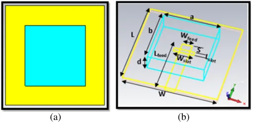
Microstrip Line (ML) Feed. In this design, a microstrip line is used as a feeding mechanism shown in Fig. 1. The DRA is fed directly with microstrip line at the same plane, and it is fully grounded at the back. This approach is commonly used for coupling an antenna. The amount of coupling can be controlled by adjusting the S value [16]. The advantages of this feeding are easy fabrication, matching and convenient for DRA array [15].
(a) (b)
Figure 1. Configuration of the single RDRA with ML feed. (a) Top view. (b) 3D view.
Aperture Coupled (AC) Feed. Figure 2 shows the configuration of the RDRA with AC feed. A slot cut in a ground plane and on the other side of the slot-fed microstrip line is etched. The slot comes with various shapes. It can be ring, U shape, rectangle or any shapes [14, 16]. However, in this design, a rectangular slot is used due to its simplicity. This feeding mechanism has an advantage in terms of minimizing the spurious radiation.
(a) (b)
Modified Structure (MS) Feed. This is a new feeding structure proposed to excite the RDRA. The idea comes from the concept of hybrid antenna. Instead of using the conventional feeding techniques, the RDRA is combined with a modified feed line. Fig. 3. shows the RDRA design with the new feeding structure.
(a) (b)
Figure 3. Configuration of the single RDRA with MS feed. (a) Top view. (b) 3D view.
The effects of using these three different feeding techniques on reflection coefficient and impedance bandwidth have been analyzed. The simulated results of scattering parameters are obtained using CST Microwave Studio Software 2014 [20] and measured using vector network analyzer. Fig. 4 presents the simulated reflection coefficient plot of the RDRA for the three feeding techniques. All three designs manage to operate at 28 GHz with an acceptable value of reflection coefficient. Fig. 5 shows the simulation and measurement results of RDRA with the new feeding structure. Good agreement between measurement and simulation results is obtained for the RDRA with selected feeding. However, in terms of impedance bandwidth and gain, all three feeding techniques give a different result. The summary of the simulated result of gain and impedance bandwidth is shown in Table 1. A microstrip line can provide a wider bandwidth, but the gain for a single-element antenna is low. Compared to aperture coupled feed, it can provide higher gain; however, the bandwidth is narrow. The new feeding structure affords to have wide bandwidth and at the same time high value of gain for single element. The modified structure feed line has been tuned and optimized to operate in 5G frequency band around 28 GHz to support the DRA as a main radiator element in this design. Actually this feeding structure can excite fundamental mode of DRA and also has its own resonance but with a narrow bandwidth. As we can see in Figs. 5 and 6, the DRA bandwidth is greater than the covering range from the feeding line. It must be noted that the first resonance is from feeding line and the second resonance from DRA which operates at TExδ11 mode.
Table 1. Summary of simulated gain and bandwidth.
Feeding Mechanism Gain (dB) Bandwidth (GHz)
Microstrip line 3.36 4.4
Aperture coupled 5.71 2.1
Modified structure 6.17 6.5
3. LINEAR ARRAY RECTANGULAR DIELECTRIC RESONATOR ANTENNA
Figure 4. Comparison of simulated reflection coefficient of the single RDRA for three feeding techniques.
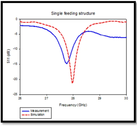
Figure 5. Simulated and measured reflection coefficient of the proposed single RDRA with modified line feed.
Figure 6. Simulated and measured reflection coefficient of the modified structure feeding.
on the geometry and dimension of the DRA elements, spacing between elements, number of elements, mode of operation and feed arrangement. In this section, the parametric studies for linear array DRA is discussed in order to get the optimum dimension of overall antenna and a good antenna performance. The parametric study was carried out for two cases which are the number of elements (n) and the spacing between elements (d).
Number of elements (n). Theoretically, as the number of elements increases, the gain will also increase. Gain is closely related to the directivity of the antenna where efficiency of the antenna is taken into account as shown in Eq. (2). According to Eq. (3), radiated electrical field (E) can be determined by number of elements (n), electrical field at the same field point produced by a single DRA positioned at the center array (Eo), and array factor (AF). WhenE is increasing, gain will definitely increase too.
G=η×D (2)
whereG = gain;η = efficiency; D= Directivity
It is good to have a minimum number of elements that can provide high gain. This will reduce the overall size of an antenna. Thus, the parametric study on the number of elements is conducted in order to determine number of antennas to be used. Fig. 7 shows the simulated reflection coefficient plot for one to five elements. The reflection coefficient plot and impedance bandwidth are similar for all numbers of elements. This is because the RDRA is excited with a separated feeding similar to a single element.
Figure 7. Simulated reflection coefficient plot.
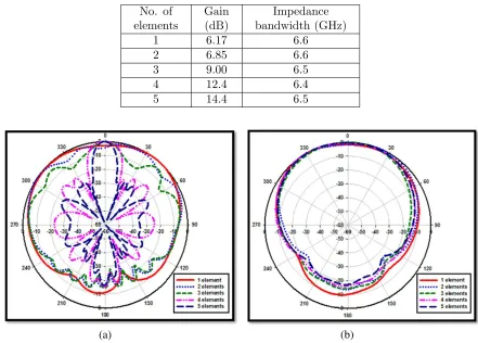
Table 2. The gain and impedance bandwidth of linear array.
No. of elements
Gain (dB)
Impedance bandwidth (GHz)
1 6.17 6.6
2 6.85 6.6
3 9.00 6.5
4 12.4 6.4
5 14.4 6.5
(a) (b)
However, the differences are on gain and radiation pattern.
The targeted value for gain is achieved by having more than four radiating elements in an array. Thus, this proposed linear array design is suggested to use the minimum number of elements, which is four. Besides that, theH-plane radiation pattern also becomes more directive as the number of elements increases as shown in Fig. 8. The directive shaped beam is needed for 5G applications because it can be used to steer the beam for a specific angle direction [21].
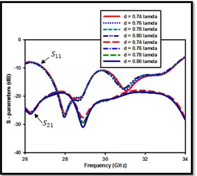
Element Spacing (d). The distance between elements in array is studied because of mutual coupling’s effect. Mutual coupling depends not only on the spacing between elements, but also on the structure, dimensions and dielectric constant of the DRA and the mode of operation. According to [15], the mutual coupling between DRAs is generally greater than microstrip antennas because the level of coupling between DRA elements increases with the thickness of the substrate or the height of the DRA. Therefore, a suitable value for element spacing is chosen to reduce mutual coupling. After fixing the number of elements to four, it is crucial to investigate the side-by-side isolation (S21,S32, and S43) for each element. Since the side by side isolation provides similar graph, hence in Fig. 9, the graph ofS21is used to representS32andS43of each design. From theS-parameters plot, the isolation in the operating frequency range is accepted with a value below −15 dB. Fig. 10 shows the simulated rectangular plot of RDRA while in Table 3, the simulated side lobe level and gain are presented. 0.78λis chosen as it is the smallest value of element spacing that produces the highest gain while retaining an acceptable side lobe level.
Figure 9. Simulated s-parameters plot. Figure 10. Simulated rectangular plot of RDRA.
Table 3. Simulated side lobe level and gain for different element spacing.
Element spacing (λ) Side Lobe Level (dB) Gain (dB)
0.74 λ −15.8 12.3
0.76 λ −14.4 12.3
0.78 λ −12.8 12.4
0.80 λ −11.2 12.4
4. MEASURED RESULTS AND DISCUSSION
Figure 11. The prototype linear array DRA. Figure 12. Reflection coefficient plot.
(a) (b)
Figure 13. Simulated and measured radiation pattern at 28 GHz. (a)H-plane. (b) E-plane.
resonant frequencies and bandwidths of the arrays deviate a bit from simulation result. There is a slight frequency shift between the two results; however, it still covers the desired frequency of 28 GHz. The impedance bandwidth obtained is more than 2.1 GHz while the gain is 12.1 dB. The H-plane and E-plane of radiation pattern are presented in Fig. 13.
5. CONCLUSION
ACKNOWLEDGMENT
The authors wish to thank the Ministry of Education (MOE) (under FRGS Grant: 4F733) and Universiti Teknologi Malaysia (UTM) (under GUP: Vot 05H62) for sponsoring this work. The members of Wireless Communication Centre (WCC) are also acknowledged for providing facilities and rendering necessary technical assistances.
REFERENCES
1. Rappaport, T., S. Sun, R. Mayzus, et al., “Millimeter wave mobile communications for 5G cellular: It will work!,”IEEE Access, Vol. 1, 335–349, 2013.
2. Sulyman, A. I., A. T. Nassar, M. K. Samimi, et al., “Radio propagation path loss models for 5G cellular networks in the 28 GHz and 38 GHz millimeter-wave bands,”IEEE Commun. Mag., 78–86, 2014.
3. Wong, H., K. B. Ng, C. H. Chan, and K. M. Luk, “Printed antennas for millimeter wave application,”International Workshop on Antenna Tech., 411–414, 2013.
4. Chin, K. S., H. T. Chang, J. A. Liu, et al., “28-GHz patch antenna arrays with PCB and LTCC substrates,”Cross Strait Quad-Regional Radio Science and Wireless Technology Conference, Vol. 1, 355–358, 2011.
5. Tong, K. F., K. Li, and T. Matsui, “Performance of millimeter-wave coplanar patch antennas on low-k materials,”PIERS Online, Vol. 1, No. 1, 46–47, 2005.
6. Wang, D., H. Wong, K. B. Ng, and C. H. Chan, “Wideband shorted higher-order mode millimeter-wave patch antenna,” IEEE Antennas and Propagation Society International Symposium, 5–6, 2012.
7. Balanis, C. A., Antenna Theory: Analysis and Design, Wiley-Interscience, New Jersey, 2005. 8. Jamaluddin, M. H., R. Gillard, R. Sauleau, et al., “A dielectric resonator antenna (DRA)
reflecarray,”Proc. European Microwave Conference., 25–28, 2009.
9. Shahadan, N. H., M. R. Kamarudin, N. A. Zainal, et al., “Investigation on feeding techniques for rectangular dielectric resonator antenna in higher-order mode for 5G applications,” Applied Mechanics and Materials., Vol. 781. 2015
10. Pan, Y. M., K. W. Leung, and K. M. Luk, “Design of the millimeter-wave rectangular dielectric resonator antenna using a higher-order mode,”IEEE Trans. Antennas and Propag., Vol. 59, 2011. 11. Jamaluddin, M. H., R. Gillard, R. Sauleau, et al., “Dielectric resonator antenna reflectarray in
Ka-band,”Antenna and Propagation Society International Symposium (APSURSI), 1–4, 2010. 12. Bijumon, P. V., A. P. Freundorfer, M. Sayer, and Y. M. M. Antar, “On-chip silicon integrated
cylindrical dielectric resonator antenna for millimeter wave applications,” Signals, Systems and Electronic International Symposium., 489–492, 2007.
13. Wang, K. X. and H. Wong, “A circularly polarized antenna by using rotated-stair dielectric resonator,” IEEE Antennas and Wireless Propag Letters, Vol. 14, 787–790, 2015.
14. Petosa, A., Dielectric Resonator Antenna Handbook, Artech House, Norwood, MA, 2007.
15. Luk, K. M. and K. W. Leung (eds.), Dielectric Resonator Antennas, Research Studies Press, London, UK, 2003.
16. Petosa, A. and A. Ittipiboon, “Dielectric resonator antennas: A historical review and the current state of the art,”IEEE Antennas and Propag. Mag., Vol. 52, 2010.
17. Costanzo, S., I. Venneri, G. Di Massa, and G. Amendola, “Hybrid array antenna for broadband millimeter-wave applications,” Progress In Electromagnetics Research, 173–183, 2008.
18. Lai, Q. H., G. Almpanis, C. Fumeaux, et al., “Comparison of the radiation efficiency for the dielectric resonator antenna and the microstrip antenna at Ka band,” IEEE Trans. Antennas Propag., Vol. 56, No. 11, 3589–3592, 2008.
20. CST MICROWAVE STUDIO 2014, CST Computer Simulation Technology AG, 2015.