Design and Analysis of Open Complementary Split Ring Resonators
Loaded Monopole Antenna for Multiband Operation
Raphael Samson Daniel*, Ramasamy Pandeeswari, and Singaravelu Raghavan
Abstract—This paper describes a compact triple-band monopole antenna based on Open Complementary Split Ring Resonators (OCSRRs) for Wireless Local Area Network (WLAN) and Worldwide interoperability Microwave Access (WiMAX) applications. The monopole antenna with engraved ground plane is used to cover WLAN frequencies (2.67 GHz and 5.47 GHz). The resonant frequency of WiMAX (3.43 GHz) is achieved by introducing OCSRR in the monopole antenna. In order to achieve multiband and good impedance matching, OCSRRs are introduced in the rectangular monopole antenna. The prototype antenna is fabricated on an FR-4 substrate having dimension of 29.4×26 ×1.6 mm3. Simulated and measured results are shown in good equivalence. The dipole radiation pattern is obtained in the elevation plane (E-plane), and omnidirectional radiation pattern is obtained in the azimuthal plane (H-plane). Parametric analysis of OCSRRs is studied to attain the best results. The proposed antenna has adequate advantages, including compact size, multiband, and impedance matching.
1. INTRODUCTION
Multiband printed monopole antenna is an embryonic necessity in the field of wireless communications. Several artificial structures have been analyzed to obtain a multiband antenna. The fractal concept [1], embedding slots [2, 3], and adding strips [4, 5] are a few among them to realize multiband antenna design. Metamaterial antennas have spurred many antenna designers in millimeter wave frequency bands due to their unusual electromagnetic properties. Open Split Ring Resonator (OSRR) and Open Complementary Split Ring Resonator (OCSRR) are a class of metamaterial. Both particles are used in the realization of many microwave devices such as antenna design [6, 7], filters [8, 9], and branch line coupler [10]. Due to sub-wavelength resonator, Complementary Split Ring Resonator (CSRR) is used for achieving a compact low-profile multiband antenna and good impedance matching [11, 12]. Therefore, the application of CSRR has received great attention for design of small antennas. OSRR has a two concentric metal rings, and the resonator is left open by elongating the metallic strips, which can be modeled as an opened series resonator. OCSRR is formed by etching a metallic part of the OSRR. Hence, OCSRR is modeled as an open parallel resonator [13]. Transmission line metamaterial can be synthesized by interdigital capacitor and thin inductive strip, which is quite useful in antenna design [14]. Different complicated structures have been studied in literature for achieving multiband.
In this paper, a compact triple-band monopole antenna is designed using a simple radiating structure. The multiband and good impedance matching are achieved by using engraved ground plane and an OCSRRs loaded monopole antenna. OCSRRs change the resonance characteristics of the conventional antenna. Thus, it is responsible for creating new resonance frequency and good impedance matching.
Received 31 July 2017, Accepted 6 October 2017, Scheduled 12 October 2017 * Corresponding author: Raphael Samson Daniel ([email protected]).
fSRR= 2π2
1− 2−
Re(εr)R32 (1)
Therefore, fOCSRR= 12 fSRR.
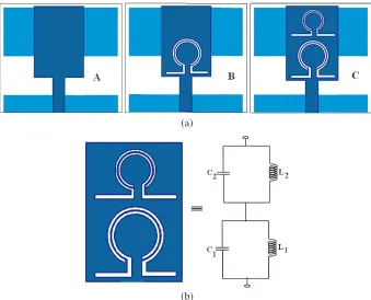
Here, R1 is the outer ring radius, R2 the inner ring radius, w the width of the ring, and Re(εr) the real part permittivity of FR-4 substrate (εr = 4.4 + 0.088i). Therefore, the proposed OCSRR resonates at 3.4 GHz. As shown in configuration C, one more OCSRR has been introduced to improve the impedance matching, in particular upper frequency band. The geometry of the proposed antenna is analyzed by Finite element modeling (FEM) based electromagnetic software HFSS V.15.0.
OCSRRs topology and its equivalent circuit model [6] are shown in Figure 1(b). The inductance of the OCSRRs (L1 and L2) is due to metallic strip between the slots and capacitive effects (C1 and
C2) across the slots between the metallic strip. Therefore, the resonance frequency of the OCSRRs,f0, is given by [6]
f0 =
1 2π√L1L2C1C2
(2)
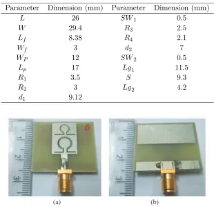
Figure 2 illustrates the layout of the proposed antenna geometry for triple-band operation. The antenna parameters are listed in Table 1. The snapshot of the fabricated antenna is shown in Figure 3.
(a)
(b)
(a) (b)
Figure 2. Proposed antenna geometry. (a) Top view. (b) Bottom view.
Table 1. Parameters of the proposed antenna.
Parameter Dimension (mm) Parameter Dimension (mm)
L 26 SW1 0.5
W 29.4 R3 2.5
Lf 8.38 R4 2.1
Wf 3 d2 7
WP 12 SW2 0.5
Lp 17 Lg1 11.5
R1 3.5 S 9.3
R2 3 Lg2 4.2
d1 9.12
(a) (b)
Figure 3. Snapshot of the fabricated proposed antenna (top view and bottom view).
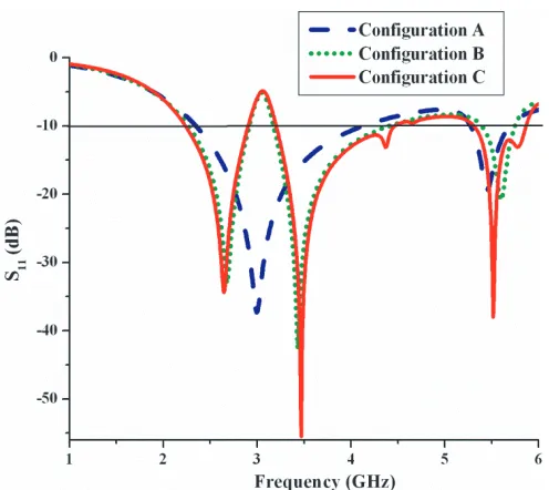
Figure 4. Simulated return loss of all the three designs.
(a) (b) (c)
Figure 5. Simulated surface current distribution at (a) 2.64 GHz, (b) 3.46 GHz, (c) 5.51 GHz.
impedance bandwidth of 660 MHz (2.23–2.89 GHz), 1240 MHz (3.21–4.45 GHz) and 530 MHz (5.32– 5.85 GHz), respectively.
The simulated surface current distributions of the proposed antenna at 2.64 GHz, 3.46 GHz and 5.51 GHz are shown in Figure 5. Figures 5(a) and 5(b) clearly indicate that at 2.64 GHz and 3.46 GHz, the current is concentrated along the bottom OCSRR whereas in Figure 5(c), at 5.51 GHz the current is concentrated along the top OCSRR. The surface current distribution clearly shows that OCSRR alters the current direction for creating a new resonance frequency and good impedance matching.
3. PARAMETRIC STUDY OF PROPOSED OCSRR
Figure 6. Simulated return loss characteristics for various values of SW1.
Figure 7. Simulated return loss characteristics for various values of RW.
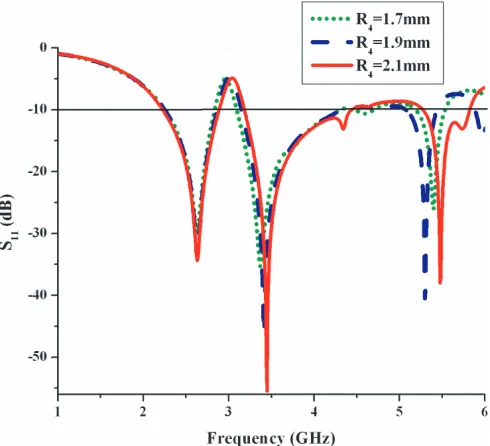
Figure 8. Simulated return loss characteristics for different values of R4.
“SW1” value decreases the resonant frequency to achieve miniaturization of the proposed antenna. Hence, the value for “SW1” is fixed at 0.5 mm. A further investigation is done to obtain an optimum value of ring width (RW). The width “RW” is varied from 0.7 mm to 0.3 mm in steps of 0.2 mm, which is depicted in Figure 7. It clearly shows that a better return loss characteristic is observed for “RW” value of 0.3 mm.
(a) (b)
Figure 9. (a) Waveguide Setup. (b) Simulated return loss characteristics for bottom OCSRR and top OCSRR.
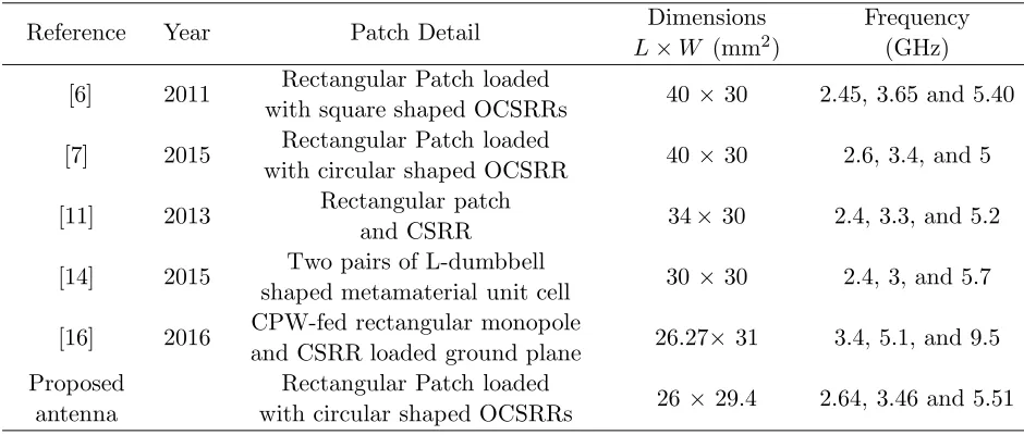
Table 2. Comparison of previously reported antennas with the proposed antenna.
Reference Year Patch Detail Dimensions
L×W (mm2)
Frequency (GHz)
[6] 2011 Rectangular Patch loaded
with square shaped OCSRRs 40 ×30 2.45, 3.65 and 5.40
[7] 2015 Rectangular Patch loaded
with circular shaped OCSRR 40 ×30 2.6, 3.4, and 5
[11] 2013 Rectangular patch
and CSRR 34× 30 2.4, 3.3, and 5.2
[14] 2015 Two pairs of L-dumbbell
shaped metamaterial unit cell 30 ×30 2.4, 3, and 5.7
[16] 2016 CPW-fed rectangular monopole
and CSRR loaded ground plane 26.27× 31 3.4, 5.1, and 9.5
Proposed antenna
Rectangular Patch loaded
To verify the significance of this proposed antenna, a comparison between the proposed antenna and other antennas in the literature is given in Table 2. From Table 2, it is observed that the proposed structure offers a low profile and multiband.
5. EXPERIMENTAL RESULTS AND DISCUSSION
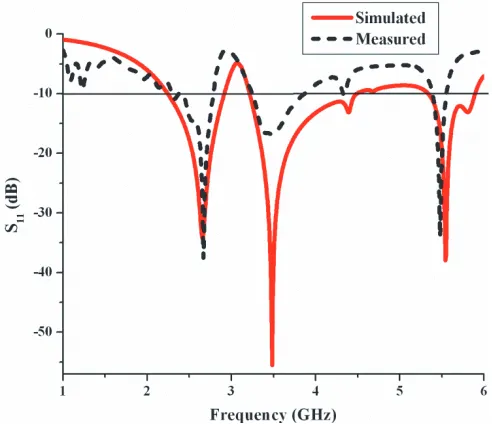
The return loss characteristics are measured using Agilent Network Analyzer E8362B. The simulated and measured return loss characteristics of the proposed the antenna are shown in Figure 10. The measured data exhibit a triple-band resonances at 2.67 GHz, 3.45 GHz and 5.48 GHz, with −10 dB impedance bandwidths of 490 MHz (2.29–2.78 GHz), 610 MHz (3.25–3.86 GHz) and 160 MHz (5.39– 5.55 GHz), respectively. The measured results greatly agree with the simulated ones with the 2.67 GHz frequency band; however, a small difference between simulated and measured results has been noticed in the middle (3.48 GHz) and upper (5.54 GHz) frequency bands. This may be due to fabrication tolerance, thick soldering of Sub-Miniature-A (SMA) connector, and measurement inaccuracy.
The radiation pattern of the proposed antenna is measured in an anechoic chamber. The simulated and measured E-plane and H-plane radiation patterns for the resonance frequencies at 2.67 GHz, 3.45 GHz and 5.48 GHz are shown in Figures 11(a)–(c). It is observed that a homogeneous dipole pattern
Figure 10. Simulated and measured return loss characteristics of proposed antenna.
(b)
(c)
Figure 11. Simulated and measured radiation patterns of the proposed antenna (a) 2.67 GHz, (b) 3.45 GHz and (c) 5.48 GHz.
is obtained in E-plane and an omnidirectional pattern obtained in H-plane. Figure 12 illustrates the gain of the proposed antenna. Measured peak gains of the prototype antenna are 2.01 dBi, 2.35 dBi and 2.47 dBi at 2.67 GHz, 3.45 GHz and 5.48 GHz, respectively.
6. CONCLUSION
A triple-band monopole antenna for WLAN and WiMAX applications is developed and presented, with a compact size of 29.4×26×1.6 mm3. An inspired OCSRRs loaded monopole antenna accounts for the new resonance frequency and good impedance matching. The resonance frequency of OCSRRs is obtained by an effective medium theory approach to verify its passband characteristics. The simulated and measured radiation characteristics are in good equivalence. The prototype of the proposed antenna has a compact size, multiband and homogeneous radiation pattern. It could be of wide use in WLAN (2.29–2.78 & 5.39–5.55) and WiMAX (3.25–3.86 GHz) applications.
ACKNOWLEDGMENT
The authors gratefully acknowledge Dr. C. K. Anandan, Professor, Department of Electronics, Cochin University of Science and Technology (CUSAT), Kerala, India for their kind support in carrying out measurements of antenna characteristics.
REFERENCES
1. Naser-Moghadasi, M., R. A. Sadeghzadeh, R. K. M. Lou, B. S. Virdee, and T. Aribi, “Semi fractal three leaf clover-shaped CPW antenna for triple band operation,”International Journal of RF and Microwave Computer-Aided Engineering, Vol. 25, 413–418, 2015, doi: 10.1002/mmce.20875. 2. Kunwar, A., A. K. Gautam, and K. Rambabu, “Design of a compact U-shaped slot triple
band antenna for WLAN/WiMAX applications,” AEU-International Journal of Electronics and Communications, Vol. 71, 82–88, 2017, doi: 10.1016/j.aeue.2016.10.013.
3. Kumar, R., P. Naidu V, and V. Kamble, “A compact asymmetric slot dual band antenna fed by CPW for PCS and UWB applications,” International Journal of RF and Microwave Computer-Aided Engineering, Vol. 25, 243–254, 2015, doi: 10.1002/mmce.20855.
4. Nair, S. M., V. A. Shameena, C. M. Nijas, C. K. Aanandan, K. Vasudevan, and P. Mohanan, “Slot line fed dual-band dipole antenna for 2.4/5.2 GHz WLAN applications,” International Journal of RF and Microwave Computer-Aided Engineering, Vol. 22, 581–587, 2012, doi: 10.1002/mmce.20609. 5. Zhao, H., L. Yan, X. Zhao, and K. Huang, “A compact tri-band patch antenna with notched ground for WLAN/WiMAX communication,”Journal of Electromagnetic Waves and Applications, Vol. 25, 250–256, 2012, doi: 10.1080/09205071.2013.743498.
6. Herraiz-Mart´ınez, F. J., G. Zamora, F. Paredes, F. Mart´ın, and J. Bonache, “Multiband printed monopole antennas loaded with OCSRRs for PANs and WLANs,” IEEE Antennas Wireless Propagation Letters, Vol. 10, 1528–1531, 2011, doi: 10.1109/LAWP.2011.2181309.
7. Pandeeswari, R. and S. Raghavan, “A CPW-fed triple band OCSRR embedded monopole antenna with modified ground for WLAN and WiMAX applications,” Microwave and Optical Technology Letters, Vol. 57, 2413–2418, 2015, doi: 10.1002/mop.29352.
8. V´elez, A. F. Aznar, J. Bonache, M. C. Vel´azquez-Ahumada, J. Martel, and F. Mart´ın, “Open complementary split ring resonators (OCSRRs) and their application to wideband CPW band pass filters,” IEEE Microwave Wireless Components Letters, Vol. 19, 197–199, 2009, doi: 10.1109/LMWC.2009.2015490.
13. Dur´an-Sindreu, M., F. Aznar, A. V´elez, J. Bonache, and F. Mart´ın, “Analysis and applications of OSRR and OCSRR loaded transmission lines: A new path for the design of compact transmission line metamaterials,” Metamaterials, Vol. 4, 13–148, 2010, doi: 10.1016/j.metmat.2010.03.004. 14. Sharma, S. K., J. D. Mulchandani, D. Gupta, and R. K. Chaudhary, “Triple-band
metamaterial-inspired antenna using FDTD technique for WLAN/WiMAX applications,” International
Journal of RF and Microwave Computer-Aided Engineering, Vol. 25, 688–695, 2015, doi:
10.1002/mmce.20907.
15. Imaculate Rosaline, S. and S. Raghavan, “Split ring loaded broadband monopole with SAR reduction,” Microwave and Optical Technology Letters, Vol. 58, 158–162, 2016, doi: 10.1002/mop.29519.