Available Online at www.ijcsmc.com
International Journal of Computer Science and Mobile Computing
A Monthly Journal of Computer Science and Information Technology
ISSN 2320–088X
IJCSMC, Vol. 4, Issue. 8, August 2015, pg.381 – 390
RESEARCH ARTICLE
Performance Evaluation of EPON Link at 1550 and
1350 nm using NRZ and RZ Modulation Technique
Priyanka Sehgal, Gaurav Soni
Department of Electronics and Communication EngineeringAmritsar College of Engineering and Technology, Amritsar
Abstract
The research work has evaluated the performance of the proposed link in terms of Q- Factor and BER at wavelength of 1550 nm and 1350 nm at transmission distance of 30 km. The comparison has also been drawn among the proposed EPON link with NRZ and RZ modulation scheme. In this work, simulative investigation to evaluate the performance of EPON
transmission links using NRZ and RZ modulation schemes at high transmission rate is reported. Further, the results have been reported by compensating the degradations introduced by fiber dispersion using DC fiber for the proposed EPON
transmission links and a comparison is presented for evaluating the performance of such systems with NRZ and RZ modulation technique. Our result shows that the NRZ performs better than RZ modulation scheme as the later severely suffered with fading problems due to fiber dispersion. In case of NRZ modulation technique, an improvement in BER ratio and total power received is achieved in comparison to RZ modulation technique.
Keyword: - EPON, NRZ, RZ, BER
1. INTRODUCTION
named as Ethernet in the First Mile (EFM) study group and is focused on instituting EPON standards underneath the architecture of the IEEE 802.3 protocol. In June 2004, the IEEE 802.3ah standard is approved by IEEE Standard Board and then officially released. EPON is on the basis of the Ethernet standard, unlike other PON technologies, which are on the basis of the ATM standard. Allowing you utilize economies-of-scale of Ethernet, and provides simple, easy-to-manage connectivity to Ethernet-based, IP equipment, both at the client premises and at the central office. Much like other Gigabit Ethernet media, it's well-suited to transport packetized traffic, that will be dominant at the access layer, in addition to time-sensitive voice and video traffic and thus has 2N optical transceivers. Curb-switched Ethernet uses one trunk fiber and thus saves fiber and space in the Central Office (CO). However it uses 2N+2optical transceivers and needs electric power in .EPON also uses just one trunk fiber and thus minimizes fibers and space in the CO, and also only uses N+1optical transceivers. It takes no electric power in the field. The drop throughput may be around the line rate on the trunk link. EPON can support downstream broadcast such as for example video. The IEEE 802.3ah EPON specification defines Multi-Point Control Protocol (MPCP), Point-to-Point Emulation (P2PE), and two 1490/1310 nm PMDs for 10and 20 km, required to construct an EPON system. Typical EPON-based systems may include extra features above the IEEE 802.3ah standard, including security, authentication and dynamic bandwidth allocation.
1.2 ARCHITECTURE OF ETHERNET PASSIVE OPTICAL NETWORKS
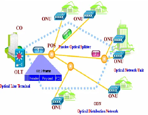
A typical EPON system is composed of OLT, ONU, and ODN (see Figure 1).
Figure 1 EPON Network Architecture
The OLT (Optical Line Terminal )resides in the Central Office (CO) and connects the optical network to the metropolitan-area network or wide-metropolitan-area network, also referred to as the backbone or long-haul network. OLT is both a transition or router and a multi-service platform which supplies EPON-oriented optical interfaces. Form network assembling and access functions, OLT may also perform bandwidth assignments, network security and management configurations based on the customers' different QoS / SLA requirements.
ADVANTAGES OF EPONS
EPONs are simpler, most efficient and less expensive than alternate multiservice access solutions. Its key benefits are
(1). HIGHER BANDWIDTH
EPONs provide the highest bandwidth to customer of any other PON system. Its other benefits of having higher bandwidth are a. More subscribers per PON.
b. More bandwidth per subscriber. c. Higher split counts.
d. Video capabilities. e. Better QOS.
(2). LOW COST
EPONs provide the following cost reduction opportunities :
a. Eliminate complex and expensive ATM and SONET elements and dramatically simplify network architecture. b. Long-lived passive optical components reduce outside plant maintenance.
c. Standard Ethernet interfaces eliminate the need for additional DSL or cable modems. d. No electronics in outside plant reduces need for costly powering and right-of-way space.
(3). MORE REVENUE
a. EPONs can support a complete bundle of data, voice and video services which allows carriers to boost revenues by exploiting the broad range and flexibility of service offering available.
b. Revenue opportunities from EPONs include:
c. Support for legacy TDM, ATM and SONET services.
d. Delivery of new gigabit Ethernet, fast Ethernet, IP multicast, and dedicated wavelength services. e. Provisioning of bandwidth in scalable 64kbps increments up to 1 gbps
f. Tailoring of services to customer needs with guaranteed SLAs.
g. Quick response to customer needs with flexible provisioning and rapid service reconfiguration.
2. Related Work
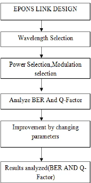
3. Proposed Technique
Fig. 2 Flow chart of proposed Technique
4. Result Analysis NRZ
Non-return to zero encoding is used in slow speed synchronous and asynchronous transmission interfaces. With NRZ, a logic 1 bit is sent as a high value and a logic 0 bit is sent as a low value. The reciever may lose synchronization when using NRZ to encode a synchronous link which may have long runs of consecutive bits with the same value.
Fig 3. Eye diagram of downstream
Fig 4. Eye Diagram of Upstream The above Fig 4 represents the NRZ eye diagram in Upstream.
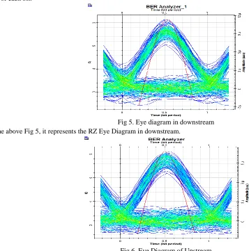
5.2 RZ
RZ (return-to-zero) refers to a form of digital data transmission in which the binary low and high states, represented by numerals 0 and 1, are transmitted by voltage pulses having certain characteristics. The signal state is determined by the voltage during the first half of each data binary digit . The signal returns to a resting state (called zero) during the second half of each bit.
Fig 5. Eye diagram in downstream In the above Fig 5, it represents the RZ Eye Diagram in downstream.
Comparison between NRZ and RZ
Fig 7. BER
The above Fig 7, shows the comparative analysis of Bit Error Rate (BER) between NRZ and RZ in downstream. In this figure the red line represents the NRZ Signal in downstream and black line represents the RZ signal in downstream. X-axis represents the Length in KM and Y-axis represents the Min. log of BER.
Fig 8. Power
The above Fig 8., shows the comparative analysis of Max. Total Power between NRZ and RZ in downstream. In this figure the red line represents the NRZ Signal in downstream and black line represents the RZ signal in downstream. X-axis represents the Length in KM and Y-axis represents the Maximum Total Power in dBm.
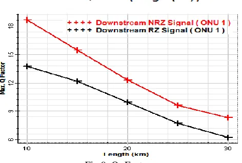
The above Fig 9., shows the comparative analysis of Q- Factor between NRZ and RZ in downstream. In this figure the red line represents the NRZ Signal in downstream and black line represents the RZ signal in downstream. X-axis represents the Length in KM and Y-axis represents the Max. Q- Factor.
Fig 10. SNR
The above Fig 10., shows the comparative analysis of SNR between NRZ and RZ in downstream. In this figure the red line represents the NRZ Signal in downstream and black line represents the RZ signal in downstream. X-axis represents the Length in KM and Y-axis represents the Max. SNR in dB.
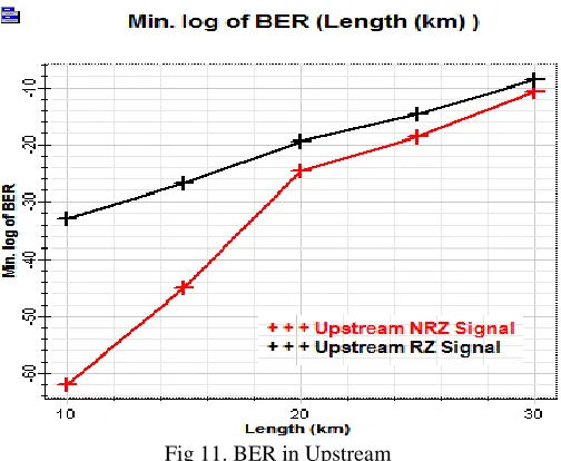
Fig 11. BER in Upstream
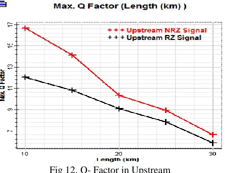
Fig 12. Q- Factor in Upstream
The above Fig 12., shows the comparative analysis of Q- Factor between NRZ and RZ in Upstream. In this figure the red line represents the NRZ Signal in Upstream and black line represents the RZ signal in upstream. X-axis represents the Length in KM and Y-axis represents the Max. Q- Factor.
5. Conclusion
In this system, there is chromatic dispersion in fiber which significantly limits the transmission distance. For a single mode laser, the symmetrical sidebands are created on the optical carrier. Due to fiber chromatic dispersion, a relative phase shift is added to these sidebands which depends on the wavelength, fiber distance and modulation frequency. Each sideband mixes with the optical carrier in the optical receiver. If the relative phase between these two components is 180◦, the components destructively interfere and the mm-wave electrical signal disappears. The detected signal power has been considered as reported. Therefore, it is important to compensate the fiber chromatic dispersion. The research work has evaluated the performance of the proposed link in terms of Q- Factor and BER at wavelength of 1550 nm and 1350 nm at transmission distance of 30 km. The comparison has also been drawn among the proposed EPON link with NRZ and RZ modulation scheme. In this work, simulative investigation to evaluate the performance of EPON transmission links using NRZ and RZ modulation schemes at high transmission rate is reported. Further, the results have been reported by compensating the degradations introduced by fiber dispersion using DC fiber for the proposed EPON transmission links and a comparison is presented for evaluating the performance of such systems with NRZ and RZ modulation technique. Our result shows that the NRZ performs better than RZ modulation scheme as the later severely suffered with fading problems due to fiber dispersion. In case of NRZ modulation technique, an improvement in BER ratio and total power received is achieved in comparison to RZ modulation technique. The comparisons have clearly shown the effectiveness of the proposed technique.
6. Future Work
This work has not considered only OSSB and ODSB modulation schemes , therefore in near future we will consider some more modulations techniques inorder to evaluate the effectiveness of the proposed technique further. Also limited number of quality parameters are considered therefore in near future some more quality parameters will be considered for better evaluation.
References