Available Online atwww.ijcsmc.com
International Journal of Computer Science and Mobile Computing
A Monthly Journal of Computer Science and Information Technology
ISSN 2320–088X
IJCSMC, Vol. 4, Issue. 7, July 2015, pg.93 – 102
RESEARCH ARTICLE
DESIGN AND IMPLEMENTATION OF
INTELLIGENT TRAFFIC LIGHT SYSTEM
K. VISHNUVARDHAN REDDY M.Tech(Embedded system) [email protected] JITS. Karimnagar LAXMAN SHANIGARAPU Assistant Professor [email protected] JITS. Karimnagar
ABSTRACT: Traffic lights are the signaling devices used to manage traffic on multi-way road. These are positioned to control the competing flow of the traffic at the road intersections to avoid collisions. By displaying lights (red, yellow and green), they alternate the way of multi-road users. The implementation of traffic Light Controller can be through a Microcontroller, Field Programmable Gate Array or Application Specific Integrated Circuit. FPGA implementation is advantageous over ASIC and microcontroller; number of IO ports and performance compared to microcontroller and implementation with FPGA is less expensive compared to ASIC design. This paper presents the FPGA implemented low cost advanced TLC system using ChipScope Pro and Virtual Input Output. The TLC implemented is one of the real and complex signaling lights in Kingdom of Bahrain, for pedestrian way included four roads and sensors and camera assisted motorway.
Index Terms—ChipScope Pro, Virtual Input Output, Integrated Controller, Field Programmable Gate Array.
I. INTRODUCTION
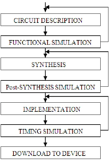
Fig. 1 FPGA Design Flow
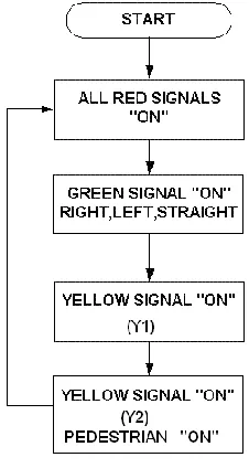
Fig. 2 TLC Flow Chart
The sequential order of the flow chart helps the programmer in the design regarding the flow of the program. North/ south-bound traffic will start with a green signal light while all the other lanes being red, the traffic will be stopped. After a predetermined time, the north/south traffic light turns yellow and then to red, allowing the east/west signal light to be green and the same sequence as the north/south-bound traffic is followed. The system will continue to be in this loop until an indication of a vehicle in a left turn lane occurs. When the signal light turns yellow, the controller scans the inputs. If high, then the program will jump to a subroutine which has a different light sequence. This sequence controls the main lights along with the left turn lights. After completion of the subroutine sequence, the program returns to the main loop. The flow chart can be applied to any number of road structures. In this paper, a four road structure is considered in which the four directions labeled with four labels namely North, South, East and West. Each traffic lane has set of three traffic light signals, “Red, Yellow, and Green”, which operates similar to genera signaling lights i.e., it changes from red to green and then to yellow and after that back to red signal.
In the conventional traffic light system there are four LEDs used on each sides in order to reduce the power consumption we make use of motor and reduce the number of LEDs to five as shown in fig.2.
In the above structure we use five LEDs which is three red LEDs and each yellow and green LEDs. All the red LEDs will always remain on and yellow , green LEDs turn on with The sequential order of the flow chart helps the programmer in the design regarding the flow of the program. North/ south-bound traffic will start with a green signal light while all the other lanes being red, the traffic will be stopped. After a predetermined time, the north/south traffic light turns yellow and then to red, allowing the east/west signal light to be green and the same sequence as the north/south-bound traffic is followed. The system will continue to be in this loop until an indication of a vehicle in a left turn lane occurs. When the signal light turns yellow, the controller scans the inputs. If high, then the program will jump to a subroutine which has a different light sequence. This sequence controls the main lights along with the left turn lights. After completion of the subroutine sequence, the program returns to the main loop. The flow chart can be applied to any number of road structures. In this paper, a four road structure is considered in which the four directions labeled with four labels namely North, South, East and West. Each traffic lane has set of three traffic light signals, “Red, Yellow, and Green”, which operates similar to genera signaling lights i.e., it changes from red to green and then to yellow and after that back to red signal.
The motor will rotate every time after the yellow LED.
In the fig. 2.(a) it is shown that the there is one LED in the North South direction which is red and fig.2.(b) there is one LED in west direction which is red and two LEDs in east direction which are green and yellow. The green LED will remain on and after that yellow then the motor will rotate 90‟ to the south direction and again the green will on and the red LED of the north direction will move to the east direction and hence the rotation continue through whole cycle. Finite state machine has been used to control the traffic lights at the intersection of a north-south and an east-west route. Initially all RED signals are ON and after few seconds, GREEN of a signal light in one particular direction will be ON to allow the traffic in straight, right and left paths[5-7].
III.STATE MACHINE, STATE TABLE AND HARDWARE DESCRIPTION
The TLC state diagram shown in Fig. 3 illustrates that whenever cnt=00 and dir=00,then green light in north direction will be ON for few seconds and red signal light in all other directions namely west, south and east will be ON. When cnt=01 and dir=00 then yellow light (y1) will be ON for few seconds and when cnt=01 yellow light (y2) and pedestrian north will be ON and then dir is incremented by one and cnt is assigned to zero. So when cnt=00 and dir=01, the green light in east direction will be ON for few seconds and all red lights in other directions be ON.
A finite state machine (FSM) is a mathematical model of computation used to design the sequential logic circuits. The machine is in only one state at a time, the state it is in at any given time is called the current state. It can change from one
state to another when initiated by a triggering event or condition, this is called transition.The output is produced by the system in order to the response of the input signal frominput handling module [9-10].
In this design, PTLC uses a standard two process finite state machine where one process is used to change states of every clock cycle while the other process is used to combinatorial calculate what the next state should be based on the current inputs and the current state.
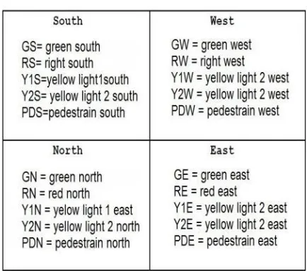
Table I. Terms used in State Diagram
direction label in order to distinguish the outputs from each other with their states. In the traffic light controller program there will be two inputs namely clock and reset. When the two variables are „1‟ then the TLC will start working. Initially that is when reset is „0‟ then the red signal lights in all the directions will be ON and when reset is „1‟, then the traffic light controller system will be on assigning cnt and dir variables to 00 where cnt and dir respectively represent the states and the four directions in the state machine.
IV.RESULTS
4.1 RTL SCHEMATIC:
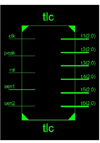
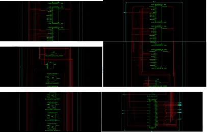
Fig. 4 RTL Schematic
Fig. 5 RTL Schematics with 5 Counters, Adder, D Flip-flop, 4 Comparators, Inverter, FSM
4.2 SIMULATION RESULTS:
Fig.7 Sensor1=0, Sensor2=0
The simualtion results are carried out by using modelsim 6.4b . Here two inputs are indicated with Sensor1=0, Sensor2=0. and out put is indicated with R. When the clock signal is „1‟ and reset signal is „0‟ the output will be displayed.
Fig. 8 Sensor1=0, Sensor2=1
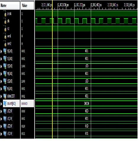
Fig. 9 Sensor1=1, Sensor2=0
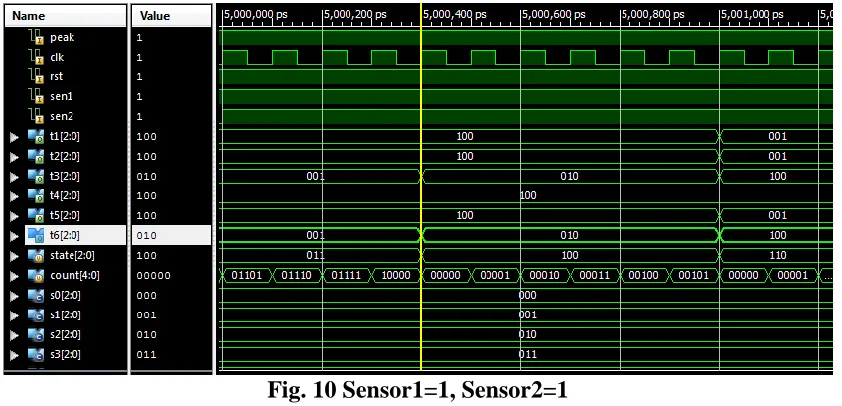
The simualtion results are carried out by using modelsim 6.4b . Here two inputs are indicated with Sensor1=1, Sensor2=1. and out put is indicated with R. When the clock signal is „1‟ and reset signal is „0‟ the output will be displayed.
Fig. 10 Sensor1=1, Sensor2=1
REFERENCES
El-Medany, W.M., & Hussain, M.R. (2007) FPGA-Based Advanced Real Traffic Light Controller System Design.
Proceeding of 4th IEEE International Workshop on Intelligent Data Acquisition and Advanced Computing Systems: Technology and Applications, ISBN: 978-1-4244-1347-8, pg. 100 – 105.
Chan, S.S., Deshpande, R.S. & Rana, J.G. (2009) Design of Intelligent Traffic Light Controller Using Embedded System.
Proceeding of 2nd International Conference on Emerging Trends in Engineering and Technology, ISBN: 978-1-4244-5250-7, pg. 1086-1091
Liu, Y. & Chen. X. (2009) Design of Traffic Lights Controlling System Based on PLC and Configuration Technology.
Proceeding of International Conference on Multimedia Information Networking and Security 2009, ISBN: 978-0-7695-3843-3, pg. 561-563.
Kulkarni, G.H. & Waingankar, P.G. (2007) Fuzzy logic based traffic light controller.
Proceeding of International Conference on Industrial and Information Systems 2007, ISBN: 978-7-4244-1151-1, pg. 107-110
Norhuzaimin, J. & Maimun, H.H. (2005) The Design of High Speed UART. Proceeding of Asia Pacific Conference on Applied Electromagnetics, ISBN 0-7803-9431-3, pg. 306-310.
STEPHEN BROWN, JONATHAN ROSE, “FPGA and CPLD architectures: A Tutorial,” Design & Test of Computers, IEEE, Volume 13,Issue 2, summer 1996 Page(s):42 – 57.
Wikipedia, “Programmable Logic device,”
http://en.wikipedia.org/wiki/Programmable_logic_device.
Wikipedia, “Traffic light,”
http://en.wikipedia.org/wiki/Traffic_light.