69
Embedded C - USB Driver Controller
Ms.Sneha Jaiswal1, Mr. Sanamdikar Sanjay Tanaji2 E & TC Dept1, Instrumentation Engg. 2
G.S Moze College of Engg, Balewadi, pune1, PDEA’S College Of Engg, Manjari, pune2 University Of Pune, Pune, Maharasthra1, 2
[email protected]1, [email protected]
Abstract-USB driver controller is nothing but USB host and the concern of host is to pinpoint USB client. USB O-T-G
(ON-THE-GO) empowers two USB gadgets to share data with each other without requiring assistance of pc. In any case, OTG expose to be a kind of architecture in which interconnected nodes share assets amongst each other without the usage of a consolidate regulatory system. On second thought, OTG propose the dual-role device (DRD), skillful of functioning either host or peripheral. The perfect charm of OTG is that host and peripheral device swap roles if significant. Prior concept of OTG, design of embedded host was formerly popularized in universe of USB [14] building them exceptional suited to embedded environment than pc with its enormous resources, vast scope for drivers and application software. USB was developed as quick fix to pc interconnectivity [1].
USB is super popular employment for data transfer from system/computer to another [1]. The appeal for these products is rising constantly with fame; there is obligation for them to impart both with USB peripherals and directly with each other when PC not available.
Fig.1 OTG universe
Index Terms: USB driver controller, USB O-T-G, embedded host, attach detection protocol (ADP), session request protocol
(SRP), host negotiation protocol (HNP), USB driver, device driver, computer application
1.
I
NTRODUCTIONUSB is a brand new type of I/O interface standard promoted by Compaq, Microsoft, IBM, DEC and other companies in 1995[2,3] .USB is a flash drive data storage device that includes flash memory with an integrated USB interface [17]. Few materials have been written on USB. One of the prominent materials is the book written by Jan Axelson explaining in detail how USB works [15]. USB has developed into one of the super popular interface for exchanging the data between a host PC and its peripherals. This idea prospered in the mid-1990s defining the cables, connectors and protocols used for connection, communication and power supply between computers and electronic devices. USB has definitely replaced a variety of earlier interfaces such as serial and parallel ports, as well as separate power chargers for portable devices [4].
the several machines is collected for the analysis process. As well as using such systems in the remote field is actually challenging where the dilemma of network for the GPS and GSM model take place.
Fig. 2 Data logger system
However on the other hand as per our system architecture the USB embedded controller is a portable device which can be easily mounted on any application system.USB is an easy to use interface from the developers and users point of view having advantages such as ease of use and accessibility [16]. As we have used the PIC microcontroller which is having implanted memory, provides the storage for the data collected from the application system. It becomes very straightforward and easy to take the back up from one of the machine just by applying the pen drive to the USB embedded controller. One more advantage is this controller is user friendly and the person dealing with the device need not require the familiarity of the whole computer. In this, the data is transferred by compelling just one switch after applying the pen drive. We have favored PIC microcontroller belonging to the family of PIC24FJ128GB110. USB is most famous application for the data transmission purpose from a system or a computer to another. Today most of the devices that are mainly PCs in the classic sense have a need to connect directly to peripherals. Printers can connect directly with cameras, for example, or mobile phones may need to connect to the USB headsets. These non-PCs have the computing resources to guide a USB host function, but they need to function in ways which is entirely different from standard PC hosts. All the same they will provide host capability for most of the devices; it’s unreasonable to require them to support the full range of USB peripherals.
A targeted host is only required to support the peripherals on its Targeted Peripheral List. There are two categories of Targeted Hosts:
A. EMBEDDED Hosts: A product that has a Standard-A
receptacle supported by a USB Host Controller. Embedded Hosts have a particular set of targeted peripherals, as described in their targeted peripheral list(TPL).
B. OTG: Device that provides both host and peripheral
capabilities over a single Micro-AB receptacle, as outlined in USB OTG & EHv2.0
So here with the help of PIC microcontroller we are trying to prepare an embedded host. This can be connected rather to
connect to the application systems whose backup p the analyzed data is necessary to be taken for the study purpose or for the further processing. The USB On-The-Go and Embedded Host Supplement to the USB 2.0 specification introduced three new protocols, Attach Detection Protocol (ADP), Session Request Protocol (SRP) and Host Negotiation Protocol (HNP)[2]
2. ARCHITECTURE
Standard USB employs a master/slave design; in this system a USB host plays the role as a the protocol master, and a USB 'Device' plays the role as the slave. The Host only can schedule the configuration and data transfers over the link. Data transfers cannot be initiated by the device, they can only respond to requests given by a host.
2 . Architecture
Standard USB uses a master/slave architecture; in this a USB host plays the role as a the protocol master, and a USB 'Device' plays the role as the slave. The Host only can schedule the configuration and data transfers over the link. Data transfers cannot be initiated by the device, they can only respond to requests given by a host.
OTG throws a light on the concept that a 'Device' can perform both the master and slave roles, and so equally changes the terminology. With OTG, a 'Device' can act as either a 'Host' (acting as the link master) or a 'Peripheral' (acting as the link slave). The Device connected to the 'A' end of the cable at start-up (known as the A-device) acts as the Default Host, while the 'B' end acts as the Default Peripheral (known as the B-device).USB On-The-Go describes Host/Peripheral role swapping only for the case of a one-to-one connection where two OTG devices are directly connected. Role swapping does not work through a standard hub, as one device will act as the Host and the other as the capabilities and the same USB Standard-A port used by PCs.
Super Speed OTG devices, Embedded Hosts and peripherals are supported through the USB On-The-Go and Embedded Host Supplement [8] to the USB 3.0 specification.
2.2 Protocols
The USB On-The-Go and Embedded Host Supplement to the USB 2.0 specification introduced three new protocols[12,13,14], Attach Detection Protocol (ADP), Session Request Protocol (SRP) and Host Negotiation Protocol (HNP).
71 based behavior and the possibility for a device to display
attachment status. It periodically measuring the capacitance on the USB port to check whether there is another device attached, a dangling cable or no cable. When a change in capacitance is determined, this change should be large enough to indicate device attachment is detected then an A-device will provide power to the USB bus and look for device connection. A B-device will generate SRP and wait for the USB bus to become powered.
SRP request host to start a session, the host activates power bus for the peripheral, and the sessions commence or start. Fig 3 shows the session between the host and the device
Fig. 3 Session request protocol(SRP)
HNP starts as a host and interrogates the peripheral. If peripheral is device, then it remains host and vice versa that is if the peripheral is host then it becomes device. Fig.4 shows the HNP session
Fig 4. Host Negotiation Protocol(HNP) session
One of the important functions of HNP is to accommodate users who have connected the A and B devices in the wrong direction for the task they want to perform. For example, a printer is connected as the A-device (host), but cannot function as a host for a particular camera, since it doesn't understand the camera's representation of print jobs. When that camera knows how to talk to the printer, the printer will use HNP to switch to the slave role, making the camera the host to the printer so that the user's pictures will get printed without juggling cables. The USB On-The-Go and Embedded Host Supplement to the USB 3.0 specification introduce an additional protocol, Role Swap Protocol (RSP). This achieves the same purpose as HNP (i.e. role swapping) by extending standard mechanisms provided by the USB 3.0 specification. Products following the USB On-The-Go and Embedded Host Supplement to the USB 3.0 specification are also required to follow the USB 2.0 supplement in order to maintain backwards compatibility.
2.2.1 Device roles
USB OTG states two roles of devices: OTG A-device and OTG B-device. This term defines which side supplies power to the link, and which is initially the host. The OTG A-device is a power supplier, and an OTG B-A-device is a power consumer. The default link configuration is that A-device act as USB Host and B-device is a USB Peripheral. The host and peripheral modes may be exchanged later by using HNP. Because every OTG controller supports both roles, they are often called "Dual-Role" controllers rather than "OTG controllers".
For IC designers, an attraction of USB OTG is the ability to get more USB capabilities with fewer gates. This means many gates to test and debug. Also, most gadgets need to be just a Host, or just a Device. OTG hardware design merges all of these controllers into a single.
2.2.2Backward compatibility
USB OTG devices are backward-compatible with USB 2.0 [13] (USB 3.0 for Super Speed OTG devices) and will behave as standard USB Hosts or Devices when connected to standard (non-OTG) USB devices. The main exception is that OTG hosts are only required to provide enough power for the products listed on the TPL, which may or may not be enough to connect to a peripheral which is not listed. A powered USB hub may sidestep the issue if supported since this will then provide its own power according to either the USB 2.0 or USB 3.0 specifications.
3. USB IMPLEMANTATION
Fig4: Block diagram of USB Driver Controller.
16x2 LCD display is used to show the status of the data being sent to the pen drive from the microcontroller memory which is inputted by the keypad which is interfaced to the microcontroller. LED is used to indicate the dataflow or the operations done by the microcontroller. When we give any input from the keypad, that data will be stored in the microcontroller memory in the form of a file.
Then when we connect the pen drive to the USB embedded controller the data will be sent to the pen drive. This transfer of data is the main purpose of our USB embedded controller (USB host). This transfer of data is done by the method of file handling, as we have programmed the microcontroller for this particular operation. The entire code is written in the embedded C language. A 5V power supply is given to the microcontroller by a power supply connected externally. Reset pin is also connected to the embedded controller to reset the microcontroller as well as LCD display.
Software- In our project we are going to write our code in
embedded C in MPLAB X which runs on Windows® OS, MAC® OS and Linux. The below is the algorithm for the implementation of the above idea when developed into a kit.
• Start the application machine. • Power on the circuit.
• Insert the USB client (pen drive) in the USB slot. • When USB gets detected press reset button. • Remove USB client (pen drive) from the kit. • We can read the log file for analysis using
computers.
4. DEVELOPMENT OF USB DEVICE DRIVER
USB devices are having some interfaces [2, 9, 11]. In the USB protocol, here the interface is made up of a number of endpoints representing a basic function and is also which an object USB device driver controls. In this paper, as shown in Fig. 5 the interaction of USB driver with application kit. Here the I/O operation of a user mode program wants to say, read or collect some data from a device can be described as follows [8, 9, 10].Firstly it calls for windows application programming interface (API) to create file to open the device and create the connection to the device. In the next stage then the subsystem module implements this API by invoking some platform-dependent system service interface to reach a kernel-mode routine.
Then the I/O manager will surround the device driver and then it will create an IRP according to the request information applications will interact with the device and which passes to an entry point in some device driver. I/O request Packet (IRP) embodies and calls control code to create an IRP (I/O request Packet) with an I/O control code and then calls driver to send the I/O request Packet (IRP) to the USB bus driver.
The USB bus driver subdivides USB request Block (URB)
into packets, conveys to the USB bus and sends them to the USB host controller driver. Drivers even though execute in kernel mode and can therefore talk directly to their hardware using facilities provided by the hardware abstraction layer
(HAL) to access the hardware. Thus USB controller will control the communication
between the host controller and the USB devices through HAL function calls. Lastly, this operation results to the application in the reverse order after a driver has finished with the I/O operation
Fig.5 interaction of usb driver with application
The advantages of the above kit when developed are as follows
It can be used for remote areas where installation of pc is not possible.
Power is saved as we don’t need to supply any extra power supply to the pc.
Also space is saved as there is no need to allocate any special space.
It is a portable device and thus can be easily mounted on any application.
It does not require maintenance.
They are not expensive.
They don’t have limitation like the range of the device from the server computer as in case of Bluetooth, Zig-bee, GSM, and GPS.
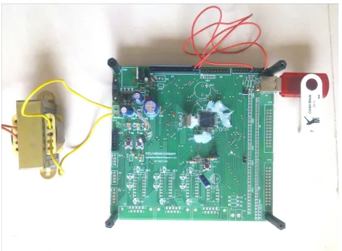
5. RESULT
73 Fig. driver controller using embedded C
6. CONCLUSION
The purpose of the project is to create a USB driver controller which acts as host and helps peripheral to gather data from several applications. This system will be deployed in industries such as data logger where mounting of a computer is not possible. Our circuit will help in reducing the overhead cost and maintenance which is usually required for the installation of computer. An external secondary memory can be added to the circuit to increase the memory capacity of the device so that it can store or transfer data depending on the application
7 FUTURE SCOPE
We have used IC PIC24FJ128GB110 which is having 16384 bytes data memory and 128kb program memory so we can directly use it for industrial purpose for data logging. With the help of this microcontroller IC family we are planning to prepare a universal driver circuit which can be used in various industrial applications such as I2C data logger, USB data logger, SPI data logger and many more.
As our device is portable and doesn’t required separate power supply it can be easily mount in the remote areas for data logging in the projects like wind mill power generation plants.
REFERENCES
[1] www.usb.org/developers/onthego
[2] Anderson D. Universal serial bus architecture. Addison Wesley publishing company, pp. 13-24,1999
[3] Wright Nick, Judd Bob. Using USB as a data acquisition interface. Journal of evaluation engineering . Vol. 43, No. 6, pp. 20-26, 2004
[4] "SuperSpeed USB 3.0: More Details Emerge". 6 Jan 2009.
[5] ^ On-The-Go and Embedded Host Supplement to the
USB 2.0 Specification Revision 2.0 plus ECN and errata, July 14, 2011
[6] USB-On-the-Go-Specification Settled. Heise.de, Heinz
Heise.[dead link]
[7] On-The-Go and Embedded Host Supplement to the USB 3.0 Specification Revision 1.0, July 1, 2011 [8] Gereaux, Dean A. USB Device driver. Journal of dr.
Dobb, vol. 29, no.4, pp. 60-64, April 2004
[9] Y. P. Su The design of WDM driver based on USb bus. Journal of computer knowledge and technology, No. 36, pp. 142-144 , 2005
[10]Nadolny, Jim, Kelly, Kieran. USB interfaces and EMC. Journal of compliance engineering, vol. 16N.4 pp. 5-10, 1999
[11]Compaq, Hewlett-packard, Intel , lucent, . universal serial bus specification 2.0. Implementers Forum, 2000 [12]"Universal Serial Bus Revision 2.0 specification".
Universal Serial Bus Micro-USB Cables and Connectors Specification. USB Implementers Forum, Inc. 4 April 2009.
[13]www.maximintegated.com [14]www.usb.org
[15]J. AXELSON, USB COMPLETE- The developers guide, 4th ed. Madison: Lakeview research LLC, 2009 [16]John Hyde, USB Design, a technical introduction to 2.o
white papers.
[17]Chapter 13. USB Devices Written by Nick Himba_ Modifications for handbook made by Murray Stokely
Authors Profile
Mr. Sanamdikar Sanjay Tanaji was awarded BE in 1998 and masters degree in 2002 in Instrumentation engg. He is also persuing PPG in Biomediacl instrumentation From SMRTU Nanded. He has provided his valuable guidance in AISSMS Woman College of Engineering, Pune and currently working with PDEAsLAGCOE ,Hadasar, PUNE as Assistant Professor.