1710)0
~
~~~
®Reference Manual
MINOR REVISION [January, 1960]
This edition, Form A22-7003-1, is a minor reViSion of the preceding edition but does not obsolete Form A24-7003-0. The changes in this edition reflect the increased number of tape units that can be attached to the system because of the addition of two more channel controls.
Page
IBM 7070 DATA PROCESSING SYSTEM ... . 5
7 Units of the IBM 7070 IBM 7070 Instructions . . . 10
Autocoder Mnemonics . . . . . . . . . . . . . . .. 13
IBM 7070 Basic Fortran . . . . . . . . . . . . .. 14
Format of Operation-Code Text . . . . . . .. 16
OPERATIONS INVOLVING ACCUMULATORS ... 17
LOGIC CODES . . . 42
INDEX-WORD CODES . . . 60
BLOCK TRANSMISSION . . . 72
Channel Control 1, 2, 3, and 4. . . . 72
Process Channel Control .. . . . . . . . . . .. 74
CORE-TO-CORE BLOC~ TRANSMISSION . . . 75
TABLE LOOKUP . . . 83
MAGNETIC TAPE . . . 89
IBM 729 Tape Units . . . . . . . . . . . . . . . .. 91
Operating Principles . . . . . . . . . . . . . .. 92
Features of IBM 7070 Tape Operations . . . .. 95
Tape Operation Codes . . . . . . . . . . . . . . . . .. 98
DISK STORAGE . . . 108
Disk Storage Operation Codes . . . . . . . . . 112
UNIT RECORD . . . 117
Card Input-Output Operation Codes ... 117
IBM 7500 Card Reader . . . 120
Operating Keys and Signal Lights . . . . . . 121
7500 Card Reader Control Panel . . . 122
7500 Card Reader Control-Panel Summary .. 146
IBM 7550 Card Punch . . . 149
Operating Keys and Signal Lights . . . 150
Control Panel . . . . . . . . . . . . . . . . . 151
7550 Card Punch Control-Panel Summary .. 173
Contents
Page IBM 7400 Printer . . . 175Print Unit . . . 175
Operating Keys and Signal Lights . . . . . . . . . 176
Control Panel . . . 178
Tape-Controlled Carriage . . . 195
Other Control Panel Hubs . . . 201
IBM 7400 Control-Panel Summary . . . 204
INQUIRY . . . 208
Operation . . . 208
Operation Code . . . 212
AUTOMATIC PRIORITY PROCESSING . . . 215
Priority Operation . . . 218
Types of Priority ... . . . . . . . . . . . . . . 218
Unit-Record Priority . . . 218
Inquiry Priority . . . 218
Tape Priority . . . 218
Disk Storage Priority . . . 222
Priority Codes . . . 223
FLOATING DECIMAL . . . 229
PROGRAMMING SUMMARIES . . . 243
Functional Chart of 7070 Operation Codes .. 243
List of IBM 7070 Instructions by Category ... 249
Core Storage and Register Addresses ., .... 252
Op Codes that Allow Accumulator Addresses 253 Op Codes that Use Field Definition ... 253
Store and Add-to-Storage Codes . . . 254
Index of 7070 Operation Codes by Autocoder Mnemonics . . . 255
Clearing a Specified Portion of Core Storage to Zeros . . . . . . . . . . . . . . . 258
CONSOLE . . . 260
Operating Panel . . . . . . . . . . . . . . . . . 261
Console Typewriter . . . 265
Operating Keyboard . . . . . . . . . . . . . . . 266
[image:4.617.80.472.136.693.2]IBM
7070
Data Processing System
The IBM 7070 is an electronic data processing system that covers the range from medium-scale through large-scale processors, by its own variety of configurations.
It can be a card system only, an intermediate tape sys-tem, or a full-scale tape-disk syssys-tem, depending on the requirements of the user. Moreover, its processing and storage capabilities can be increased as the requirements increase.
Solid-State Design
The electronic circuits of the IBM 7070 use transistors, instead of vacuum tubes. Because of the smaller size of transistors, (Figure 1), their use in a data processing system results in three types of saving:
1. Space requ ·~ements are reduced.
2. Air-conditioning requirements are reduced due to the lower heat output of transistors.
3. Power requirements are reduced.
FIGURE 1.
Tube Transistor
FIGURE 2. SMS CARD, FRONT SIDE, ACTUAL SIZE
Standard Modular System (SMS)
The circuitry of an IBM 7070 is comprised of many
SMS cards. Each card can be easily inserted into the system or removed from it. Figure 2 shows a typical SMS card, and the various types of components that can be put on a single card. The prongs are the means of plugging the card into the system. Figure 3 shows the reverse side of· a card, which contains a printed circuit r'tAnnAr'ft;r\rr +1-" ... ________ +,.. _ _ ... 1_ -::- £ ___ __ A. _ . 1 .~,
-~~~~~--~Aub ~H,,", ,,",'VUJ../:''VU\.d.J.L'' U.lJ. L.lJ.v 11. Vlll ;:'1UC; W 1lU v u e another and with the prongs at the bottom. Each of the 16 contacts at the bottom is connected to one of the prongs shown in Figure 2.
Functional Components
MAGNETIC-CORE STORAGE: The IBM 7070 contains magnetic-core storage in capacity of either 50,000 numerical digits or 99,900 digits, organized into 5000 or 9990 words of 10 digits each.
FIGURE 3. SMS CARD, REVERSE SIDE, ACTUAL SIZE MAGNETIC TAPE: A full-capacity 7070 can have up to
40 IBM 729 Magnetic Tape Units attached. DISK STORAGE: A 7070 system can include as many as
four storage units, making the available disk-storage capacity 48 million numerical digits.
UNIT RECORD INPUT AND OUTPUT: Up to three card readers can be used with a 7070, each with a rated speed of 500 cards a minute. Output consists of any combination of card punches or printers, up to a total of 3. Cards are punched at a rated speed of 250 a minute by each punch unit; the rated speed of the printer is 150 lines a minute. !!':Q!..!!.!:!~: A.AJI.~ ~~~j~ ~:; t~~ illuuuaI-iiiquii-Y 5ldL.iUl1~ alC available, for request of information and typed reply.
PROCESSING: The programming unit of the 7010
con-tains three accumulators, with registers. and cir-cuitry to perform stored-program instructions, ad-dressing data and instructions, all arithmetic func-tions, and a wide variety of logic operations.
CONSOLE: The 7070 contains a console, for display,
Reference Manual
This manual gives complete instructions in the use of the operation codes; operation of the tape units, unit-record machines, inquiry stations and console; control-panel wiring of the unit-record machines; and descrip-tions of special features such as block transmission and automatic priority processing. Its purpose is to assist in planning, programming, and testing 7070 programs; and to aid in training sales representatives, systems per-sonnel, planners, programmers, and test-center person-nel, on the system. Although the manual is technical in its approach, it is not an engineering or highly sci-entific description of the 7070.
Units of the IBM 7070.
A full-capacity 7070 system consists of a number of separate units. This is a list of these units, in approxi-mate type-number order, showing the maximum num-ber of each unit available in a single 7070 s.ystem:
r:---,
IBM
No. 729 7150 7300 7301 7500 7400 7550 7600 7601 7602 7603 7604 7605 7900
Name
Maximum number in an IBM 7070 system Magnetic Tape Unit 40
Console 1
Disk-Storage Unit 4 Magnetic-Core Storage 1
Card Reader 3
Printer ~
Card Punch j 3
Input/Output Control
Arithmetic and Program Control Core-Storage Control
Input/Output Synchronizer Tape Control
RAMAC® Control 1
Inquiry Station 10
Figure 4 is a schematic representation of these com-ponents. Note that the two largest units are the
Arith-metic and Program Control, IBM 7601; and the IBM
7301 Magnetic-Core Storage unit, with its IBM 7602
Core-Storage Control. These units comprise the nerve center of the system. The 7601 Arithmetic and Program Control executes the stored-program instructions, bring-ing each instruction from core storage for this purpose.
The stored program operates directly on data in core
storage only. It brings data to and from the cores by means of instructions to read a card, to punch, print, read tape, etc. Note that data transmitted to and from the unit-record equipment, the inquiry stations and the
7500
I
I
I
7605L
Card ReadersRAMAC
!C.-I
ControlI
Channels 1 and 2I
I
Channels 3 and 4I
I.---L-.
I
I I
II
I
I
729I
I
7604I
I
7604i
I
I I
I
II
i
I
II
I
L__
_JL_
__~7602 Core Storage Control
7301 Magnetic Core Storage
FIGURE 4. SCHEMATIC OF 7070 COMPONENTS
console, goes to and from core storage through the Arithmetic and Program Control.
IBM 729 TAPE UNITS: As many as 40 magnetic tape units, in four groups of 6 each, can be used with the system (see Magnetic Tape section).
IBM 7150 CONSOLE: This unit provides manual control
of the operation, display of core-storage words, and typed output under control of the stored program (see Console section).
IBM 7300 DISK-STORAGE UNITS: As many as four disk
files can be used in a 7070 system (see Disk Stor-age section).
IBM 7500 CARD READER, 7400 PRINTER, AND 7550
CARD PUNCH: (See Unit-Record section).
IBM 7600 INPUT/OUTPUT CONTROL: This unit contains
a magnetic drum, revolving at a speed of 12,500
rpm. It is used as intermediate storage to synchro-nize core storage with the unit-record equipment, and the inquiry stations, as described in the sec-tions on those units.
IBM 7602 CORE-STORAGE CONTROL: Data brought to or
from core storage is addressed by this unit. The stored program sends the address to the 7602,
which then causes the designated data to be read to or from core storage.
IBM 7603 INPUT/OUTPUT SYNCHRONIZER: This unit,
between the unit-record equipment and the syn-chronizer drum, contains timing and translating circuitry.
FIGURE 5. MAGNETIC-CORE STORAGE
BIT CODE
0 1 2 3 6
1
I I
D D
D
2
I
D I
D
D
3
I
D
D
I
D
ALPHA SIGN4
D
I
D
I 0
(/)
D
0
I I
D
w :::> 5
<
>
I-Q
I
D D
D
I
0 6 MINUS SIGN
7
D
I
0
D
I
8
D
D
I D
I
9
D
0
D
I I
PLUS SIGN0
0
I I
0
D
FIGURE 6. TWO-OUT-OF-FIVE FIXED-COUNT CODE
IBM 7604 TAPE CONTROL: Data to be written on tape
is brought from core storage to this unit and thence to the tape unit. Data read from tape goes to this unit and thence to core storage. Data to and from the disk -storage units also comes through this unit. The unit cont~ins the two tape/RAMAc chan-nel controls, described under Block Transmission.
IBM 7605 RAMAC CONTROL: This unit contains timing,
translating, and addressing circuity for all disk-storage operations. It controls data transmission between the disk-storage units and the 7604 Tape Control.
IBM 7301 Magnetic-Core Storage (Figure 5)
Core storage is best described as the working storage
Data read from any of the input-output or storage units -the card readers, printers, punches, tape units, disk-storage units, inquiry stations, and the console-is brought to core storage. Similarly, any data brought to any of those units is brought from core storage.
CAPACITY: Model 1 of the IBM 7301 contains 5000
words of storage; Model 2 contains 9990 words. A word consists of 10 numerical digits and a sign, which can be plus, minus, or alpha. Because alpha coding requires two digits for each character, each alphabetic word contains five characters.
ADDRESSING: Each word in core storage is addressable.
The addresses are 0000-4999 for a Model 1 unit, and 0000-9989 for a Model 2 unit.
BIT-CODE STRUCTURE: Each digit in core storage is
represented by a combination of two bits out of a possible five. The total number of possible com-binations is ten-one for each numerical digit. As shown in Figure 6, the bit positions are designated 0, 1, 2, 3, and 6. The digits 1 to 9 are each com-posed of two bits, the sum of which equals that number. Zero is designated by the 1-2 combination. A 9 code in the sign position denotes plus; a 6, minus; and a 3, alpha. Only the 0, 3, and 6 bits are used in the sign positions.
ALPHA CODING: An alphamerical word in core storage contains five characters, each represented by two digits. Figure 7 shows all the alphabetic, numeri-cal and special characters included in this coding. Shown with these alphamerical codes are the mag-netic-tape BCD code, the punched-card code, and core-storage coding for numerical words (digits 0-9) . The characters are in two-digit-code se-quence.
NOTES:
1. Cannot be read into the IBM 7500 Card Reader, nor are they trans· lated on output to the 7550 Card Punch, 7400 Printer, 7900 Inquiry Station, or the Console typewriter.
2. Cannot be read by the 7500 Card Reader unless they are wired as the units position of numeric words. Similarly on punching or printing, these codes (60,70) are invalid.
3. This code cannot be wired to read or punch by the 7070 unit record equipment.
4. Generated by the 7070 controls on write operations, and not trans· lated on read operations. This card code (11·7·8) cannot be entered through the 7500 Card Reader.
5. The tape segment mark is generally a single·character Tape record. This character is not translated and placed in 7070 storage if the
CA8421 configuration appears as the first character of a tape record. I n this case the End of Segment condition is signalled to the 7070 via a final status word condition code.
It is possible to read the TSM as a character within a tape record (other than the first and to write the TSM from 7070 storage as part
of a record.
6. The tape mark is handled in the same fashion as the tape segment
mark.
Character
Blank
t:l or)
GM$ &or + $
*
% or (
SM # or =
@orl TM + o A B C o G H I
o
K L M N o P Q RRM
=F
S T U V W X y Z o 2 3 4 5 6 7 8 9 Delta ..1Card Code 12·3·8 12·4·8 12·5·8 12·6·8 12·7·8 12 11·3·8 11·4·8 11·5·8 11·6-8 11 0·1 0·3-8 0-4·8 0·5·8 0·6·8 0·7·8 3-8 4·8 5·8 6-8 7·8 12·0 12·1 12-2 12·3 12·4 12-5 12-6 12·7 12-8 12·9 11·0 11·1 11-2 11·3 11·4 11·5 11·6 11·7 11·8 11-9 0-2·8 0-2 0·3 0·4 0-5 0-6 0-7 0·8 0·9 o 2 3 4 5 6 7 8 9 11·7-8 Core Storage 2·Digit Alphamerical Code 00 15 16 17 18 19 20 25 26 27 28 30 31 35 36 37 38 39 45 46 47 48 49 60 61 62 63 64 65 66 67 68 69 70 71 72 73 74 75 76 77 78 79 80 82 83 84 85 86 87 88 89 90 91 92 93 94 95 96 97 98 99 Magnetic Tape BCD Code
CA CBA821 BA84 CBA841 CBA842 BA8421 BA B821 CB84 B841 B842 CB Al A821 CA84 A841 A842 CA8421 C821 84 C841 C842 8421 BA82 CBAl CBA2 BA21 CBA4 BM1 BM2 CBA421 CBA8 BA81 CB82 B1 B2 CB21 B4 CB41 CB42 B421 B8 CB81 CA82 A2 CA21 A4 CA41 CM2 A421 A8 CA81 82 C1 C2 21 C4 41 42 C421 C8 81 CB8421 Core Storage 1.Digit Numerical
Code Notes
o 1 2 3 4 5 6 7 8 9 1,5 1,6 2 2 3 4
VALIDITY CHECKING: Every digit that is moved to and from storage is tested to assure that it has two bits, neither more nor less. This is called fixed count checking.
PARALLEL TRANSMISSION: A feature of the 7070 is par-allel transmission of data to and from core stor-age. An entire word, including sign, is moved all at once, instead of one bit or one digit at a time. A channel for parallel transmission consists of 53 lines, one for each bit in each of the ten digits (50), and the sign ( 3 ). This enables a word in core storage to be moved in 6 microseconds (6 mil-lionths of a second). The channels in Figure 4 represent parallel transmission.
Information on tape, disk, and the synchronizer drum is stored serially,-each character read or written before the next character. Thus, transmis-sion of data to and from these units is serial, as indicated by the lines in the figure.
IBM 7601 Arithmetic and
Program Control
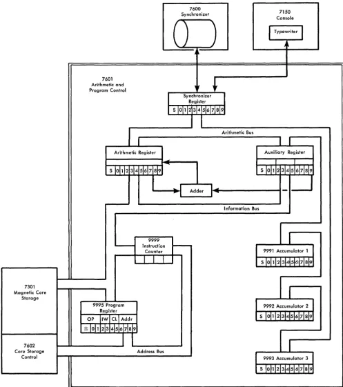
The programming feature of the 7070 is contained in the 7601 Arithmetic and Program Control Unit. Figure 8 is a simplified schematic of the programming unit. The unit contains three accumulators, the auxiliary reg-ister, the arithmetic regreg-ister, the program regreg-ister, the instruction counter, the adder, and the synchronizer register. Each of the registers and accumulators has a capacity of one word-10 digits and the sign. The in-struction counter has a capacity of 4 digits. All arith-metic operations actually take place in the adder. There are several other special registers, and of course, much more circuitry than is shown. Figure 8 is a general, functional representation of data flow. The registers shown in the figure are referred to throughout the text, in the Data Flow and Registers Affected sections under each operation code.
The three accumulators, the program register, and the instruction counter have addresses:
9991 Accumulator 1
9992 Accumulator 2 9993 Accumulator 3 9995 Program register 9999 Instruction counter
The accumulators can be addressed by certain stored-program instructions, but the instruction counter and program register, 9995 and 9999, can be addressed from the console only.
The three busses in the figure are channels for paral-lel transmissions of data: a 10-digit word with sign, is moved all at once in a maximum of six microseconds, over these busses. The information bus moves data be-tween core storage and the program register, instruction counter, arithmetic register, auxiliary register, and the tape channels. The arithmetic bus connects the three accumulators with the auxiliary register, arithmetic reg-ister, and synchronizer register. The address bus brings addresses to the 7602 Core Storage Control from the instruction counter and program register.
IBM 7070 Instruction
The program is normally sequential: each program step is located in a word with an address one higher than the last instruction. The address of each instruction is obtained by means of the instruction counter. Thus, each program step need not contain the location of the next step. This sequence can be broken by the program whenever it is desired to obtain the next program step from a word other than the one in the next sequential location. This is done by changing the contents of the instruction counter, either directly, or as the result of a logical decision.
Instruction Format
Each instruction in a 7070 program consists of 10 digits and the sign. The sign can be plus or minus, but not alpha. The digit positions are numbered 0 1 2 3 4 5 6 7 8 9 from left to right, or high-order to low-order. The general format of a 7070 instruction is:
SOl 23 45 6789
SO 1 Operation code (S indicates sign)
23 Indexing word
45 Control
6789 Address
OPERA nON CODE
The operation code (the sign and positions 0-1) de-notes the operation to take place. For example: +24, add to accumulator 2, adds the contents of the word specified by the address portion of the instruction to the amount already in accumulator 2, with the result in the accumulator after the operation is completed.
7601 Arithmetic and Program Control
Arithmetic Register
--7600 Synchronizer
)
), t
)
)
Synchronizer Register
Arithmetic Bus
7150 Console
I
Typewriterj
~
,
Auxiliary Register
I I
S 10111234516171819
~
_ _~..
Adder 1 ... 1--_ _ _ _ _ _ _ _ _-1---..
1
, 1 _ _ _ _ ... 1 ....
Information Bus
9999 Instruction
-Counter 9991 Accumulator 1
7301 Magnetic Core
Storage
7602 Core Storage
Control
9995 Program Register
OP IIWI Cli Addr
±
loh\2
3\4 5\6 7\8 9 [image:12.617.78.575.46.606.2]Address Bus
FIGURE 8. IBM 7601 DATA-FLOW SCHEMATIC
the operation codes, moreover, have multiple functions.
They are called augmented codes; the operation code is
augmented by some of the other digit positions in the
instruction. An example of this is +69, Card Control.
This code is used for all card input and punched/printed
9992 Accumulator 2
9993 Accumulator 3
INDEXING WORD
Positions 2 and 3 of an instruction specify the indexing word to be used. Magnetic-core storage contains 99 index words, each of which contains a 10-digit number with sign. They are stored in locations 0001-0099. The IW portion of a program step determines which of these 99 words is to be used (00 means no indexing). Posi-tions 2-5 and the sign of the designated indexing word are added algebraically to the address portion of the instruction, positions 6-9, considered plus, and this new address is used for the operation. The other six posi-tions of index words are available to the programmer as storage; positions 6-9 are often used for constants, decrements, and limits. Index words not needed in the program can be used as normal core-storage words. If
the indexing word is minus, the address in the instruc-tion is reduced by the value in the indexing porinstruc-tion. If
the indexing portion has a greater value and is minus, the 10's complement of the difference is obtained. For example, if positions 6-9 of an instruction contain 1875 and are indexed by the value of -2000, the resultant address is 9875, rather than 0125. (9875 is the 10's complement of 0125; 0125
+
9875 = 10,000).Every instruction in the 7070 indexable, even if po-sitions 6-9 are not used, or if they are used as a 4-digit factor rather than an address.
An indexing word can be plus or minus, but not alpha. An alpha indexing word specified in positions 2-3 of the instruction causes an error stop, whether positions 6-9 are used as an address, or not.
Any time there is a value other than 00 in the IW portion (positions 2-3) of an instruction, time is taken for indexing. This is true even if positions 6-9 are not used in the operation; indexing takes place at the be-ginning of each instruction, before the operation code itself has been interpreted.
For most operation codes, indexing adds 36 micro-seconds. There are 16 operations for which indexing adds only 24 microseconds:
-01 No operation
-03 Sense mode for sign change -03 Halt mode for sign change -03 Branch if sign change
Nap
SMSC HMSC BSC
-10, -20, -30 Branch if minus in accumulator #
BMI, BM2, BM3
+11, +21, +31 Branch if Overflow in Accumulator #
CONTROL +40 -40 +41 +41 +41 -41
Branch if low Branch if high Branch if field overflow Sense mode for field overflow Halt mode for field overflow Branch if equal
BV 1, Bv2, Bv3
BL
BH BFV SMFV HMFV
BE
FIELD DEFINITION: In many of the instructions a por-tion of a word can be processed as easily as a full
word. Positions 4 and 5 of an instruction deter-mine the part of a word to be used. The digit in position 4 denotes the starting position, the high-order position of the field. The digit in position 5 specifies the low-order position. This is called field
definition. The digit in position 4 of an instruction
can never be higher than the digit in position 5, if field definition is used (-field definition does not extend over word boundaries). A single position is defined by the same digit in positions 4 and 5. For example, 99 in those positions of the instruc-tion denotes the units posiinstruc-tion of the data word.
The field definition feature means that several fields, with like sign, can be stored in a single word, with no inconvenience to the programmer in processing an individual field. Whenever a portion of a word is used this way, its sign is the sign of the word.
OTHER THAN FIELD DEFINITION: With most of the aug-mented codes, the CL portion of an instruction does the augmenting-denoting the specific opera-tion of the several that are defined by the operaopera-tion code.
In the operation codes that specifically operate on index words, the CL portion denotes the index word to be operated on. (Positions 2-3 refer to the indexing word, and is used to modify the ad-dress, just as in other codes.)
ADDRESS
The address portion of an instruction, positions 6-9, usually refers to the storage locaton of the data (this data is sometimes called the operand). In an accumu-lator addition operation, for example, it is the address of the amount to be added; in a store operation, the lo-cation in which the data is to be stored. Another use of positions 6-9 is in branch operations, in which case the address portion contains what may be the location of the next instruction. An example of this is
+
30,Branch it Zero in Accumulator 3. If there is a non-zero
number in accumulator 3 (regardless of sign), the ad-dress of the next instruction is the next sequential loca-tion. If the accumulator is entirely zero, the contents of the address portion of the instruction are moved to the instruction counter, and the next instruction comes from that location.
With some of the augmented codes, the address por-tion does the augmenting. Posipor-tions 6-9 of every in-struction can be modified by indexing, regardless of whether they represent an address, a 4-digit factor, are part of the operation itself, or are not used at all.
EFFECTIVE ADDRESS: As many as eight positions of a
program instruction may be used to define the spe-cific digit positions of spespe-cific core-storage to be used by the instruction. Positions 6-9 contain an address. Positions 2-3 contain an indexing-word designation, or 00. Positions 4-5 define the digit positions of that word that are to be used (09 in these positions denotes a full word). The digit positions thus defined are sometimes referred to as the effective address of the instruction.
Indicators
The IBM 7070 contains 10 indicators, each of which is
turned on automatically by a condition that arises dur-ing the stored program. They are:
Accumulator 1 overflow Accumulator 2 overflow Accumulator 3 overflow Floating-decimal overflow Floating-demical underflow Sign change
Field overflow High (compare) Equal (compare) Low (compare)
The indicators can be tested at any time by the pro-gram. With the exception of the compare indicators, each indicator is automatically turned OFF by the op-eration that tests it, if it was O~. Throughout this text, the name of each indicator is in italics.
Autocoder Mnemonics
Each operation has a mnemonic representation. For example, the operation code +22, Store Accumulator 2, is written as sT2; the programmer doesn't need to know that the operation code is +22. Each augmented code has a mnemonic representation for each of the several operations it performs. The +69 Card-Control code has 8 different mnemonics. These mnemonic rep-resentations are used for A utocoder programming.
IBM 7070 Basic Autocoder
The 7070 Basic Autocoder is a programming system developed to simplify the preparation of programs for the IBM 7070 Data Processing System. The major ad-vantages of such a programming system are:
1. Operation codes are written in an easily remem-bered mnemonic form, rather than in the numerical language of the machine.
2. Every command is given a unique mnemonic repre-sentation, even though machine-language codes are the same.
3. Data to be processed is referred to symbolically, using names or other meaningful designations. 4. Instructions are not assigned core-storage locations
by the programmer; thus the addition and deletion of instructions entail no re-assignment of addresses. 5. Each routine in a program can be written
inde-pendently of the others with no loss of efficiency in the final program.
Writing a program in Basic Autocoder language re-lieves the programmer of most of the tedious clerical tasks. These tasks are turned over to the 7070 and the Basic A utocoder Processor. The processor takes the program in A utocoder language, translates the mne-monic codes into the machine-language codes, assigns core-storage addresses to the instructions and to the symbolic data references, and assembles a finished ma-chine language program.
Also, the processor performs the added function of checking for certain common coding errors, and notes these by means of messages while continuing the trans-lation process.
The IBM 7070 Basic Autocoder can assemble
pro-grams for use with any configuration of the 7070 sys-tem. The processor requires only a minimum of equip-ment: 5000 words of core storage, one card reader, and one card punch. The addition of a printer makes it possible to obtain a direct listing of the assembled pro-gram.
Basic A utocoder is described completely in the 7070 Data Processing System Bulletin (Basic Autocoder
Pro-gramming, Form 128-6021).
IBM 7070 Autocoder
IBM
FORM X28-6417-2 PRINTED IN u.S.A.Program _ _ _ _ _ _ _ _ _ _ _ _ 7070 AUTOCODER CODING SHEET Identification'::-:76~~8~o Programmed by _ _ _ _ _ _ _ _ _ _
Date _ _ _ Page No.LL.J of _ _ I 2
Line label pperation OPERAND ~asic Autocoder~ Autocoder _____
3 56 1516 2021 25 30 35
01 02 03 04 05 06 07 08 09 10
I I I 2
I 3 14 15 16
I 7 18
I 9 20 2 I 2 2
23
24
[image:15.612.42.534.59.466.2]--'-25
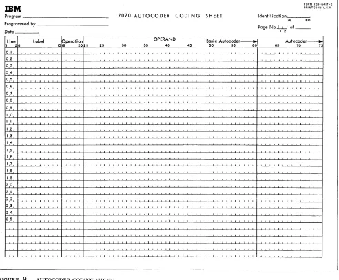
FIGURE 9. AUTOCODER CODING SHEET
convenient way to state a problem. They usually pro-duce a number of machine-language instructions.
In addition to the macro statements provided by the
IBM 7070 Autocoder, the user may add his own
macro-instructions. Thus the language can be extended.
IBM 7070 Autocoder is described in the 7070 Data
Processing System Bulletin (IBM 7070 Autocoder, Form 128-6032).
7070 Autocoder Coding Sheet
Source language programs are written on the IBM
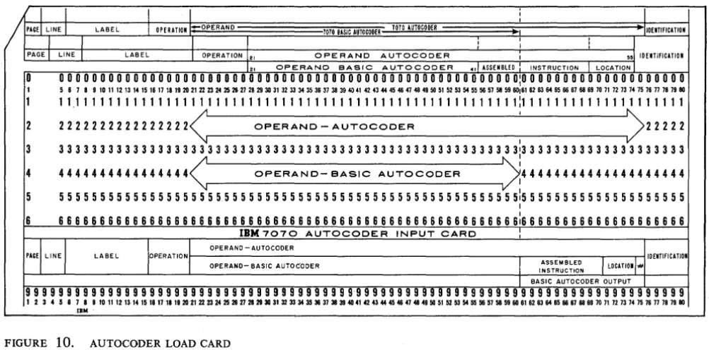
7070 A utocoder Coding Sheet, Form X24-6417 (Figure 9). This form is used for both Basic A utocoder and full Autocoder, and its use is illustrated in the bulletins mentioned. The sheet indicates the column numbers of the Autocoder load card (Figure 10), punched from each line of the sheet.
40 45 50 55 60 65 70 7":
IBM 7070 Basic Fortran
The Fortran language is a concise, convenient means
of stating the steps to be carried out by the IBM 7070
Data Processing System in solving many types of prob-lems, particularly in scientific and technical fields. As the language is simple, and the 7070, with the For-tran compiler program and the basic A utocoder assem-bly program, performs most of the clerical work, Fortran affords a significant reduction in the time re-quired to write programs.
The basic 7070 Fortran system described here is
de-signed for use with the basic IBM 7070 Data Processing
System. The basic Fortran language is acceptable to the
Fortran program produced for the expanded IBM 7070
Data Processing System.
GENERAL DESCRIPTION: The function of the basic
Fortran system for the IBM 7070 is to convert a
source program written in Fortran language into
7070 machine language. The system consists of two major parts:
1. The compiler, basic Fortran, which translates
the Fortran language statements (source program)
into basic Autocoder (symbolic) language.
2. The assembler, basic Autocoder, which
con-verts the symbolic statements produced by the compiler into a machine language program ( the object program).
The operation of the compiler and the assem-bler are automatic so that the programmer need
use only the 7070 Fortran language. Debugging
programs can be done using the Fortran source
program. Accordingly, knowledge of the machine
language or basic A utocoder is not required.
MACHINE REQUIREMENTS: Basic Fortran requires a
system that consists of the IBM 7070, one IBM
7500 Card Reader, and one IBM 7550 Card
Punch.
WRITING THE SOURCE PROGRAM: The Fortran lan-guage, which is used to write source programs for
the basic Fortran system, is a language the
struc-I struc-I
I
/
PAGEl LINE I LABEL I OPERATION -OPERAND 1010 BASIC AUTOCOOERI
II
I
PAGE I LINE I LABEL I OPERATION 12, OPERAND
ture of which closely resembles the language of mathematics. This is best described by an example
of an arithmetic statement in the Fortran language.
Consider the algebraic formula for one of the two roots of a quadratic equation:
ROOT = [-B
+
-V
B2 - 4ACJl2AThe Fortran language statement that creates a
machine language program for this calculation is:
ROOT
=
(-B+SQRTF(B**2-4.0*A*C) )/(2.0*A)
In this example the symbols denote the follow-ing:
1. The meaning of the entire statement is:
evalu-ate the expression on the right side of the equal sign and make this the value of the variable on the left.
2. The symbol * denotes multiplication.
3. The symbol ** denotes exponentiation; e. g., A**3 means A3.
4. SQR TF (arg.) is a subroutine that computes the
square root of the argument enclosed in paren-theses.
In addition to arithmetic statements, the basic
Fortran system includes other statements to specify
divisions, transfers, and input/output functions.
Full description of basic A utocoder is found in
the IBM 7070 Data Processing System Bulletin,
Basic Fortran, Form 128-6037.
I
I
1010 AUTOCOOER ~ -IiOENTIFICATION
, I ,
J
I , ,
AUTOCODER I 55] 10ENTlfiCATION
12, OPERAND BASIC AU.TOCODER .,1 ASSEMBLEO INSTRUCTION I LOCATION I
0
o
0 0 0 0 0 0 0 0 0 0 0 0 0 0 0 0 0 0 0 0 0 0 0 0 0 0 0 0 0 0 0 0 0 0 0 0 0 0 0 0 0 0 0 0 00 0 0 0 0 0 0 0 0 0:0 0 0 0 0 0 0 0 0 0 0 0 0 0 0 0 0 0 0 0I 5 6 7 8 9 10 11 12 13 14 15 16 17 18 19 20 21 22 23 24 25 26 27 26 29 30 31 32 33 34 35 36 37 38 39 40 41 42 43 44 45 46 47 46 49 50 51 52 53 54 55 56 57 58 59 60,61 62 63 64 65 66 67 66 69 70 71 72 73 74 75 76 77 78 79 80
1 11111111111111111111111111111111111111111111111111111111:11111111111111111111
2 2
n
2 222222222222< OPERAND - AUTOCODER : )222223 3 3 3 3 3 3 3 3 3 3 3 3 3 3 3 3 3 3 3 3 3 3 3 3 3 3 3 3 3 3 3 3 3 3 3 3 3 3 3 3 3 3 3 3 3 3 3 3 3 3 3 3 3 3 3 313 3 3 3 3 3 3 3 3 3 3 3 3 3 3 3 3 3 3 3 4 4444444444444444< OPERAND- eASIC AUTOCODER >:44444444444444444444
5 5 5 5 5 5 5 5 5 5 5 5 5 5 5 5 5 5 5 5 5 5 5 5 5 5 5 5 5 5 5 5 5 5 5 5 5 5 5 5 5 5 5 5 5 5 5 5 5 5 5 5 5 5 5 5 515 5 5 5 5 5 5 5 5 5 5 5 5 5 5 5 5 5 5 5 I
6 6 6 6 6 6 6 6 6 6 6 6 6 6 6 6 6 6 6 6 6 6 6 6 6 6 6 6 6 6 6 6 6 6 6 6 6 6 6 6 6 6 6 6 6 6 6 6 6 6 6 6 6 6 6 6 6:6 6 6 6 6 6 6 6 6 6 6 6 6 6 6 6 6 6 6 6
IBM 7070 AUTOCODER INPUT CARD
:
'+,,,1
r''''''''
OPERAND -AUTOCODERLABEL IOENTIFICATION
OPERAND- BASIC AUTOC·ODER
I
INSTRUCTION ASSEMBLEDJ
LOCATl01""I BASIC AUTOCODER OUTPUT
99999999999999999999999999999999999999999999999999999999999999999999999999999999
123458789rol1na"~~17~~2O~2223~2526~~2030~U3334~~~383840~n~444646~464650~~6354"56~58~60~~6364~66~6666wn72nu~n77nn8O
[image:16.617.69.570.463.711.2]IBM
Format of Operation-Code Text
The text discusses each operation code as an entity. For augmented codes, the A utocoder symbols are in the
Instruction Format section.
The eight sub-paragraphs of the text describe the various aspects of the operation code, in this sequence:
MACHINE DESCRIPTION: A functional description of what the operation code accomplishes, what its purpose is, etc. If the programmer is familiar with the general format of instructions in the 7070, this paragraph can teach him how to use this operation code.
INSTRUCTION FORMAT: A breakdown of the 10 digits and sign of the instruction, showing the function of each group of digit positions.
EXAMPLE: A machine-language example of an
instruc-tion using this operainstruc-tion code.
DAT A FLOW: A brief, general description of the actual
operation taking place, using the schematic of the programming unit (Figure 8).
REGISTERS AFFECTED: A list of the registers used by
the operation. This includes all accumulators, reg-isters, the instruction counter, and storage loca-tions that are used.
TIMING: The duration of the instruction. If the instruc-tion involves the use of an inpu.tjoutput or storage unit, the duration of the operation of that unit is also given.
COMMENTS: Any miscellaneous data that might be
helpful to the programmer - things that should be kept in mind concerning this operation code.
AUTOCODER EXAMPLE: An example of how this
instruc-tion might be written symbolically, showing the
A utocoder instruction and the machine-language
Included in this section are all the operations that in-volve the use of one or more of the accumulators, with the exception of Branch on Accumulator contents or sign, and the' floating-decimal instructions (table look-up and disk-storage operations use accumulator 3).
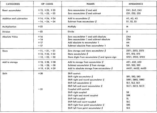
Figure 11 is a categorized list of the codes in this section, with the operation codes, names, and A
uto-coder mnemonics.
Zero Accumulator # and Add
+13, +23, +33 ZA1,ZA2,ZA3
MACHINE DESCRIPTION: The accumulator specified by the high-order digit of the operation code is set to zero. The field-defined portion of the word ad-dressed by positions 6-9 (indexable) is brought to the accumulator, to the low-order portion if less than ten digits are defined. The sign of the accu-mulator is made the same as that of the data word.
INSTRUCTION FORMAT: S O l 23 45 6789
S Always
+.
o
Designates the accumulator: 1 for accumu-lator 1, 2 for accumuaccumu-lator 2, 3 for accu-mulator 3.1 Always 3.
23 Indexing word.
45 Field definition.
6789 Address of' data word (indexable).
Operations Involving Accumulators
EXAMPLES: To move all of word 0500 to accumula-tor 1:
SOl 23 45 6789
+13 00 09 0500
After this operation is completed, the contents of word 0500 and accumulator 1 are identical.
To zero accumulator 2 and then add positions
3-5 of word 1645:
SOl 23 45 6789
+23 00 35 1645
Contents of word 1645: -81345 60193. Contents of accumulator 2: -00000 00456, regardless of contents prior to instruction.
DA T A FLOW: The entire contents of the data word, in-cluding sign, are moved in parallel. to the arith-metic register. If a full word is field-defined (09 in positIons 4-5), the contents of the arithmetic reg-ister are moved, in parallel, to the designated ac-cumulator. If less than a full word is field-defined, the field in the arithmetic register is moved, one digit at a time starting with the low-order digit, through the adder, back to the low-order portion of the arithmetic register. The contents of the arithmetic register, including sign, are then sent, in parallel, to the accumulator, with zeros inserted for all the high-order positions to the left of the field-defined digits.
REGISTERS AFFECTED: Arithmetic register, adder, and
CATEGORIES OP CODES NAMES MNEMONICS
Reset accumulator + 13, +23, +33 Zero accumulator
#
and add ZA 1, ZA2, ZA3 -13, -23, -33 Zero accumulator.#
and subtract ZS 1, ZS2, ZS3 Addition and subtraction + 14, +24, +34 Add to accumulator#
A1, A2, A3-14, -24, -34 Subtract from accumulator
#
Sl, S2, S3Multiplication +53 Multiply M
Division -53 Divide D
Absolute Value +16 Zero accumulator 1 and add absolute ZAA
-16 Zero accumulator 1 and subtract absolute ZSA
+17 Add absolute to accumulator 1 AA
-17 Subtract absolute from accumulator 1 SA
Store -11, -21. -31 Zero storage and store accumulator .# ZSTl, ZST2, ZST3 + 12, +22, +32 Store accumulator
#
S11, ST2, ST3 -12, -22, -32 Store digits from accumulator#
and ignore sign STD1, STD2, STD3 Add to storage +18, +28, +38 Add to storage from accumulator#
AS 1, AS2, AS3-18, -28, -38 Subtract accumulator
#
from storage SS 1, SS2, SS3 + 19, +29, +39 Add to absolute storage from accumiJlator#
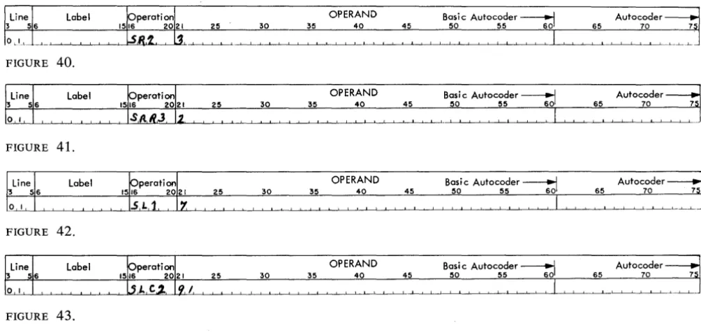
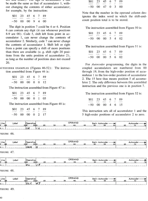
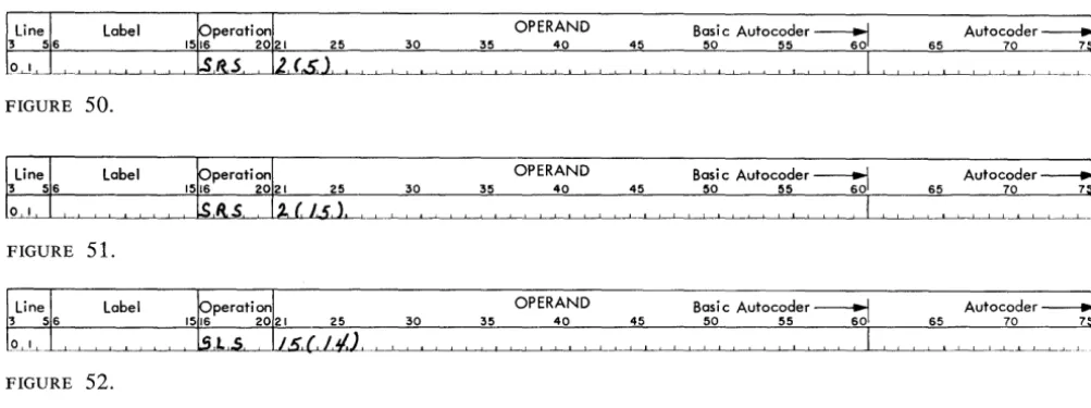
AAS 1, AAS2, AAS3Shift +50 Shift control:
Shift right accumulator
#
SR1, SR2, SR3 Shift right and round accumulator#
SRR1, SRR2, SRR3 Shift left accumulator#
Sll, Sl2, Sl3 Shift left and count accumulator#
SlC 1, SlC2, SlC3 -51 Coupled shift control:Shift right coupled SR
Shift right and round coupled SRR
Shift left coupled Sl
[image:19.615.40.540.40.399.2]Shift left and count coupled SlC Shift right from point accumulator # SRS Shift left from point accumulator # SlS
FIGURE 11. ACCUMULATOR OPERATION CODES TIMING: The duration of this code depends on the
number of digits in the field. A full word takes only 36 microseconds, however, because the digits do not have to be shifted in the arithmetic register (Figure 12).
1, for example, the instruction has the effect of moving the field to the low-order portion and re-setting the other positions. For example, if accu-mulator 1 has -54557 98643, and this instruction is given:
Number of
Digit Positions 1 2 3 4 5 6 7 8 9
Microseconds 36 48 48 48 60 60 60 72 72
FIGURE 12. TIMING - ZERO ACCUMULATOR
#
AND ADD10
36
COMMENTS: Although these codes involve
accumula-tors, they are not really arithmetic operations; there is no addition or subtraction of two values. The accumulator always takes the sign of the data word; plus, minus or alpha, regardless of the size of the field defined.
Accumulator addresses (9991, 9992, or 9993) can be used, in which cases the addressed accumu-lator is treated as a core-storage word. If the same accumulator is used, as in ZAI from accumulator
Sal 23 45 6789 +13 00 03 9991
The result in the accumulator is -00000 05455.
If field definition were 69 instead of 03, the result would be -00000 08643.
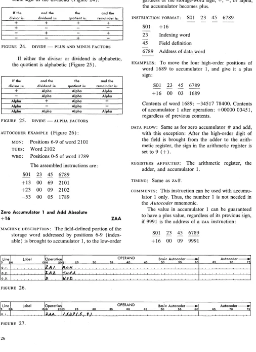
AUTOCODER EXAMPLES (Figures 13 and 14): The
sec-ond example given for this code would be written symbolically as shown in Figure 13.
The assembly program produces code
+
23 from the ZA2 operation. Field definition (3, 5) specifies positions 3-5 of an area previously def\ned asGEORGE. If GEORGE is a complete word, as in this
label OPERAND Basi c Autocoder ~ Autocoder
35 40 45 50 55 60 65 70
FIGURE 13.
OPERAND Basi c Autocoder ~ Autocoder
35
FIGURE 14.
To reset accumulator 3 and add position 4 of
SAM, indexed, (instruction PETE; Figure 14):
In the example, assume that SAM has been
de-fined as a complete word and its location is 1789. Instruction PETE is assembled as:
SOl 23 45 6789 +33 24 44 1789
The number in positions 2-5 of IW 24 is added algebraically to the 4-digit number in 1789, each time this instruction is executed.
Zero Accumulator
#
and Subtract-13, -23, -33 ZS 1, ZS2, ZS3
MACHINE DESCRIPTION: The field-defined portion of the word addressed by positions 6-9 (indexable ) is brought to the accumulator specified by position 0, to the low-order portion if less than 10 digits are defined.
If the operand is + or -, the accumulator gets the opposite sign; if the operand is alpha, the accumulator gets an alpha sign.
INSTRUCTION FORMAT: Same as ZA#, except for the
sign.
EXAMPLES: To move all of word 0500 to accumulator 1 and change the sign:
SOl 23 45 6789 -13 00 09 0500
Contents of 0500: +54380 02004. Contents of accumulator 1 after the operation: -54380 02004, regardless of previous contents.
40 45 50 55 60 65 70
To move the ,three high-order positions of word 1762 to accumulator 3, and change the sign:
SOl 23 45 6789 -33 00 02 1762
Contents of 1762: -06000 00000. Contents of accumulator 3 after the operation: +00000 00060
DATA FLOW: This is the same as for Zero Accumulator
# and Add, with this addition: After the
high-order digit of the field is brought from the adder to the arithmetic register, the sign in the arithmetic register is tested. If it is 9 (+), it is made 6 (-), if it is 6, it is made 9. If it is 3 (a), it is retained as 3.
REGISTERS AFFECTED: Same as Zero Accumulator #
and Add.
TIMING: Same as Zero Accumulator # and Add
COMMENTS: The sign of an accumulator can be changed by using this operation code with its own accumu-lator. The instruction:
SOl 23 45 6789 -23 00 09 9992
changes the sign of accumulator 2 from + to or vice-versa. There is no change if the sign is alpha.
Whenever the sign of the operand is alpha,
zs#
and ZA# produce the same result.
AUTOCODER EXAMPLE (Figure 15): Assume that JOE
has been defined as positions 0-5 of word 1551. Because no indexing or field definition is specified in the operand, the assembled instruction is:
SOl 23 45 6789 -23 00 05 1551
label OPERAND Basi c Autocoder---' Autocoder
25 30 35 40 45 50 55 601 65 70
Add to Accumulator #
+ 14, +24, +34 Al, A2, A3
MACHINE DESCRIPTION: The field-defined portion of
the word addressed by positions 6-9 (indexable) is added to the amount in the accumulator, to the low-order portion if less than 10 digits are defined. The signs of both factors are taken into account. The result is in the accumulator after the opera-tion.
INSTRUCTION FORMAT: S O l 23 45 6789
S Always +
o
Designates the accumulator: 1 for accu-mulator 1, 2 for accuaccu-mulator 2, 3 for ac-cumulator 3.1 Always 4 23 Indexing word 45 Field definition
6789 Address of data word (index able )
EXAMPLES: To add the four low-order positions of
word 0540 to accumulator 2: SOl 23
+24 00
45 6789 69 0540
To add all of word 1781 to accumulator 3: SOl 23 45 6789
+34 00 09 1781
DATA FLOW: The entire contents of the data word,
in-cluding sign, are moved, in parallel, to the arith-metic register. The entire contents of the accumu-lator are moved in parallel to the auxiliary register. The units position of the field in the arithmetic register (indicated by the digit in position 5 of the instruction) is brought to the adder; the units position of the number in the auxiliary register is brought to the adder at the same time. The result goes from the adder to the units position of the arithmetic register; a carry 1, if any, is retained in the adder. If the operation is an actual subtraction (obtaining the difference in the two numbers), the digit from the arithmetic register is converted to its 10's complement as it enters the adder: a 1 becomes a 9, a 2 becomes an 8, etc; a 0 remains as a
o.
(For all digits after the lowest-order non-zero digit, the 9's complement is used.) This is called complement add. Actual addition (obtain-ing the sum of two numbers, both plus or both minus) is called true add.In the same way, the 10's digits of the two numbers are brought to the adder, and are added
together, along with a carry 1, if any, from the addition of the units digits. The process continues until all the digits of the defined field in the -arith-metic register, and all the significant digits in the auxiliary register have been added, and the com-plete result is in the arithmetic register. This takes as many add cycles as there are field-defined digits in the arithmetic register or significant digits in the auxiliary register, whichever is greater. If the result (in a complement-add operation) must be recomplemented, the result in the arithmetic reg-ister is brought through the adder and converted to its 10's complement (recomplement is de-scribed functionally in the Timing section). For all cases in which recomplementing is required, the sign of the result is changed from plus to minus, or vice-versa.
In either true add or complement add, if the original accumulator sign is alpha, it is not changed. If the storage-word sign is alpha, the re-sult is made alpha.
The contents of the arithmetic register are sent to the accumulator, with zeros inserted for the high-order positions to the left of the result.
REGISTERS AFFECTED: The accumulator, arithmetic
reg-ister, and auxiliary register.
TIMING: The duration of this instruction depends on the number of significant digits in the result, and on whether the operation is a true add or
com-plement add. If the result is the sum of the two
numbers, the operation is called true add. If the result is the difference of the two numbers, causing the digits in one of the factors to be complemented before entering the adder, the operation is called
complement add. If a complement-add operation
causes the accumulator to change its sign (because the original accumulator value was smaller in ab-solute value than the data from storage), a
re-complement automatically takes place at the
con-clusion of the operation. For example: Accumulator 2 contains the value The storage word value is
The operation is: + 24, add to accumulator 2 The adder adds:
(lO's complement of 127) +123 -127
Let's look at a complement-add operation that does not need recomplementing:
Accumulator 2 contains the value: The storage-word value is: The operation is:
+
24, addto accumulator 2 The adder adds:
(lO's complement of 421) -456 +421
456 579 -(1) 035 Note that the result does not need recomplement-ing if the accumuluator value is greater than that of the field-defined storage word. Note also that the carry 1 is not needed to obtain the correct re-sult of +35, whereas a carry in a true-add opera-tion is part of the total (+305 added to +759 is + 1 064). Complement-add without recomple-ment thus takes less time than true-add with carry, which in turn takes less time than complement-add
with recomplement.
Figure 16 indicates the duration in microseconds of accumulator addition/subtraction operations, as determined by field size.
Number of
Dig it Positions 1 2 3 4 5 6 7 8 9 10
True Add to
Accumulator 48 48 48 60 60 60 72 72 72 72
Complement
Add to Ace. 36 48 48 48 60 60 60 72 72 72
If Recomplement 60 60 72 84 84 96 108 108 120 132
FIGURE 16. TIMING - ADD TO ACCUMULATOR
#
COMMENTS: An add operation obtains either the sum or the difference of the two factors, depending on the signs: the sum if the signs are the same, the difference if they are different. Three factors in-fluence the value and sign of the result in an add instruction:
1. The sign of the storage word (+ or -) 2. The sign of the accumulator, prior to the op-eration (+ or -)
3. The operation (add or subtract)
Figure 17 is a chart showing the signs and val-ues of the results of these combinations.
If either factor has an alpha sign, its value is considered plus in an arithmetic operation.
Re-ORIGINAL
SUM OF SIGN OF VALUE OF SIGN OF
ACCUMULATOR DATA WORD OPERATION RESULT RESULT
+
+
Add Sum+
+
-
Add Difference Sign ofGreater Value
-
+
Add Difference Sign ofGreater Value
-
-
Add Sum-FIGURE 17. ADD TO ACCUMULATOR
# -
PLUS AND MINUS FACTORSgardless of the value of the result, the sign of the result is alpha if either factor is alpha (Figure 18). Any time the contents of an accumulator are brought to zero (by adding an amount equal to it but opposite in sign if neither sign is alpha), the sign is not changed. If a
+
7 from storage is added to a -7 in an accumulator, the result in the accu-mulator is -0.ORIGINAL VALUE
SIGN OF SIGN OF OF SIGN OF
ACCUMULATOR DATA WORD OPERATION RESULT RESULT
+ Alpha Add Sum Alpha
-
Alpha Add Difference AlphaAlpha + Add Sum Alpha
Alpha
-
Add Difference AlphaAlpha Alpha Add Sum Alpha
FIGURE 18. ADD TO ACCUMULATOR
# -
ALPHA FACTORSAUTOCODER EXAMPLE (Figure 19): Assume that ALPHA
has been defined as the five high-order positions of word 0660. The assembled instruction is:
SOl 23 45 6789 +14 74 04 0660 Subtract from Accumulator #
-14, -24, -34 51, 52, 53
MACHINE DESCRIPTION: The field-defined portion of the word addressed by positions 6-9 (indexable ) is subtracted from the amount in the accumulator, from the low-order portion if less than 10 digits are field-defined. The signs of both factors are taken into account. The result is in the accumula-tor after the operation.
INSTRUCTION FORMAT: Same as A#, except for the sign.
Label OPERAND Basi c Autocoder---l Autocoder
35 40 45 50 55 601 65 70
EXAMPLES: To subtract the five high-order positions of
word 0881 fro.m the amount in accumulator 3: SOl 23 45 6789
-34 00 04 0881
To subtract the units position of word 2320 from the amount already in accumulator 1:
SOl 23 45 6789 -14 00 99 2320
DATA FLOW: Same as for A#
REGISTERS AFFECTED: Same as for A# TIMING: Same as for A#
COMMENTS: A subtract operation obtains the difference of the two factors if the signs are the same, and the sum of the factors if the signs are different. As with the add operation codes, the result is in-fluenced by the sign of the storage word and the sign of the accumulator, as well as by the subtract instruction (Figure 20).
ORIGINAL SIGN OF VALUE
SIGN OF DATA OF
ACCUM. WORD OPER. RESULT SIGN OF RESULT
+
+
Subtract Difference+
if acc. vaiue greater- if stor age value greater
+
- Subtract Sum+
-
+
Subtract Sum--
-
Subtract Difference+
if storage value greater- if acc. value greater
FIGURE 20. SUBTRACT FROM ACCUMULATOR
#
-PLUS AND MINUS FACTORSIf either factor is alpha, its value is considered plus in determining true or complement add. It
makes the sign of the result alpha in all cases (Fig-ure 21).
ORIGINAL VALUE
SIGN OF SIGN OF OF SIGN OF
ACCUMULATOR DATA WORD OPERATION RESULT RESULT
+
Alpha Subtract Difference Alpha-
Alpha Subtract Sum AlphaAlpha
+
Subtract Difference AlphaAlpha
-
Subtract Sum AlphaAlpha Alpha Subtract Difference Alpha
FIGURE 21. SUBTRACT FROM ACCUMULATOR
#
-ALPHA FACTORSAny time the contents of an accumulator are brought to zero (if neither factor is alpha), the sign is not changed. If a + 7 in storage is sub-tracted from +7 in an accumulator, the result in the accumulator is +0.
An accumulator can be brought to zero by a subtract instruction, with the address of that ac-cumulator, regardless of its sign. For example, to bring accumulator 1 to zero:
SOl 23 -14 00
45 6789 09 9991
The sign of the accuI?ulator is unfhanged.
AUTOCODER EXAMPLE (Figure 22): Assume that BETA
has been defined as positions 5-9 of word 3778. The assembled instruction is:
Multiply
+53
SOl 23 -24 00
45 6789 59 3778
M
MACHINE DESCRIPTION: The arithmetic unit can
multi-ply a 10-digit number by a 10-digit number to produce a 20-digit product. Either factor can be plus or minus, and the sign of the product con-forms to the rules of algebra: plus times plus equals plus, plus times minus equals minus, and minus times minus equals plus. If either sign is alpha, the sign of the product is alpha.
The multiplicand must be placed in accumulator 3 in a previous instruction. The multiply operation multiplies this number by the field-defined portion of the word addressed by positions 6-9 (indexable). The product is developed in accumulators 1 and 2, but is not affected by the previous contents of either accumulator; they are automatically reset before the multiply operation begins.
At the' completion of the operation, the low-order portion of the product is in accumulator 2, with the units position in the units position of the accumulator (if the product is 10 digits or less, the entire product is in accumulator 2). The ~ulti plicand is in accumulator 3 at completion of the operation.
Label OPERAND Basic Autocoder----1
25 30 35 40 45 50 55 601 65
INSTRUCTION FORMAT: SOl 23 45 6789
SOl +53
23 Indexing word
45 Field definition of the multiplier 6789 Core-storage address of the multiplier
EXAMPLES: To multiply the 10-digit number in word
1230 by the 10-digit number in word 1735: SOl 23
+33 00 +53 00
45 6789
09 1230 (multiplicand to acc. 3) 09 1735 (20-digit product,
de-veloped in acc. 1 and
2)
To multiply positions 0-6 of word 3310 by po-sitions 3-9 of word 3316:
SOl 23 45 +33 00 06 +53 00 39
6789
3310 (multiplicand to acc. 3) 3316 (14-digit product, 10 low-order positions in acc. 2, 4 high-order positions in acc. 1)
DATA FLOW: Multiplication is accomplished by the
quadrupler method. At the start of the operation,
the multiplier is brought from core storage to accu-mulator 2, to the low-order portion if less than 10 digits are field-defined. Then, factors of 1, 2, and 4 times the value of the multiplicand in accu-mulator 3 are developed and stored in 3 registers (M = value of multiplicand):
M in the arithmetic register 2M in accumulator 3 4M in the auxiliary register
If M is a 10-digit number, 2M and 4M may be-come II-digit numbers. Accumulator 3 and the auxiliary register each have an extra position, used in multiply operations, to take care of this possi-bility.
In the multiply operations, these factors are added together as determined by each multiplier digit, as follows:
Multiplier-digit value
1
2
3
4
5
6
7
8
9
Partial product developed
M
2M 2M+M 4M 4M+M 4M+2M 4M + 2M + M 4M+4M 4M +4M+M
The multiplier digits are used in right-to-Ieft (low-order to high-order) sequence. The M values are added as previously listed, for the units digit of the multiplier (in the units position of accumulator 2), to accumulator 1. Accumulators 1 and 2 are shifted one position to the right, dropping off the multiplier units digit and shifting the units position of the partial product from accumulator 1 to the high-order position of accumulator 2.
The process repeats for the 10's digit of the multiplier (now in the units position of accumu-lator 2). The M values of the multiplicand are added according to this digit, and this total is added to the partial product in accumulator 1. Another right-shift takes place, and the process repeats for each multiplier digit. If a multiplier digit is zero, there is a shift, but no adding of an M value. At the conclusion of the multiply opera-tion, M is returned to accumulator 3.
REGISTERS AFFECTED: All accumulators, the arithmetic register, the auxiliary register, and the adder. (Ac-cumulator 3 contains the multiplicand before and after the operation.)
TIMING: The duration of a multiply operation depends
on the values of the multiplier digits as well as the number of them. The quadrupler method requires 1, 2, or 3 additions of the multiplicand multiples to obtain each partial product, depending on the value of the multiplier digit.
The formula in timing a multiply operation is as follows: Total number of microseconds
=
48 [(number of 1 's, 2's, and 4's in the multiplier) +2 (number of 3's, 5's, 6's, and 8's in the multiplier) +3 (number of Ts and 9's in the multiplier) + 4 (number of zeros in the multiplier)+
4 (number of zero groups in the multiplier)]+
180. If the total is not a mUltiple of 12, use next highest mul-tiple of 12.A zero group is a zero or two-or-more adjacent zeros. For timing purposes, the multiplier is con-sidered a 10-digit number. Therefore, if field defi-nition specifies a multiplier of less than 10 digits, the high-order zeros constitute a zero group.
COMMENTS: A number is multiplied by itself, if accu-mulator 3 is the address of the multiply instruc-tion. If the value N is in word 0~04, these two instructions obtain N2:
SOl 23 45 6789
ZA3 +33 00 09 0504
M +53 00 09 9993
If this instruction is next, N3 is obtained:
Line label Operation OPERAND Basi c Autocoder ~ Autocoder - - .
3 56 1516 2021 25 30 35
o I l,A.?, IX,A,r,t;,
o 2 If, IO,f,n.iJ,t'-.-r,I,n,N,oS.
FIGURE 23.
Repeating this instruction obtains N4, etc. If the contents of accumulator 2 are stored in accu-mulator 3 after each multiplication, the values ob-tained are N2, N4, N8, etc., as long as the product values do n0't exceed 10 digit positions in size.
Polynomial nesting is the term given to adding
variables to increasing powers of a constant: a + bx +cx2
+
dx3 + ex4This can be performed efficiently on the 7070, because of the fact that the multiplicand (x) needs to be brought to accumulator 3 only once. Each product is the multiplier to obtain the next prod-uct.
Instructions
Result in Accumulator # 2 Zero-add x to Ace. # 3
Multiply by e ex
Add d to Ace. #2
Multiply x by contents of Ace. #2
Add c to Ace. #2
MUltiply x by contents of Ace. #2 Add b to Ace. #2
Multiply x by contents of Ace. #2 Add a to Ace. #2
d+
ex dx+
ex2c
+
dx+
ex2ex
+
dx2+
ex3b + ex + dx2 + ex3
bx + cx2 + dx3 + ex4
a + bx + cx2 + dx3 + ex4
AUTOCODER EXAMPLE (Figure 23): Assume that RATE
has been defined as positions 0-4 of word 2468, and DEDUCTIONS as positions 8 and 9 of the same word. The assembled instructions are:
SOl
23 45 6789 +33 00 04 2468 +53 00 89 2468Divide
-53 D
MACHINE DESCRIPTION: A 20-digit dividend is divided by a 10-digit divisor, to obtain a 10-digit quotient and a 10-digit remainder, with full sign control. Prior to the divide instruction, the dividend must be in accumulators 1 and 2, with the high-order portion in accumulator 1. The sign of accumulator 1 determines the sign of the dividend, in all cases. The divisor is the field-defined portion of the word addressed by positions 6-9 (indexable).
The abs0'lute value of the divisor must be great-er than the absolute value of the portion of the dividend in accumulator 1, at the start of the divide operation.
40 45 50 55 60 65 70 7S
I
-L __ L __I
I
At the conclusion of the divide operation, the quotient is in accumulator 2, the remainder is in accumulator 1, and the divisor is in accumulator 3.
INSTRUCtION FORMAT:
SOl
23 45 6789SOl
23 45
-53
Indexing word
Field definition of divisor 6789 Address of divisor (indexable)
EXAMPLES: To divide a 20-digit number, in words 1656 and 1657 (high-order portion of dividend in 1656), by positions 5-9 of word 1707:
SOl
+13 +23 -53
23 45 00 09 00 09 00 59
6789 1656 1657 1707
To divide a 12-digit number by a 4-digit num-ber; the 10 low-order p0'sitions of the dividend are in word 2400, indexed by positions 2-5 of IW 62. The two high-order dividend digits are in positions 8-9 of the next word, 2401 indexed by IW 62; and the divisor is in positions 4-7 of that same word:
SOl
+23 +13 -53
23 45 62 09 62 89 62 47
6789 2400 2401 2401
DATA FLOW: At the start of the divide operation, the
divisor is reset-added into accumulator 3, to the low-order portion if less than 10 digits are field-defined (it is brought via the arithmetic register and the adder).
Ti.le signs of accumulators 1 and 3 are com-pared. If they are the same, accumulator 2, which will contain the quotient when the operation is completed, is given a plus sign. If they are differ-ent, accumulator 2 gets a minus sign. If either sign is alpha, accumulator 2 gets an alpha sign.
II-digit number. (As the digits of the II-digit number go to the adder for this operation, the 10 low-or