Reference Manual
PERFORMANCE CHARACTERISTICS
7030 Data Processing System
VOLUME 1
Reference Manual
PERFORMANCE CHARACTERISTICS
7030 Data Processing System
March 8, 1961
This document contains information which is proprietary to the International Business Machines Corporation and should not be reproduced or used in whole or in part without the express permission of the IBM Data Systems Division.
Contents
FOREWORD . ~ ... " ... oil . . . " " . . . " . . . " • .. .. .. .. 1-1
PROORAMMIN"G . . . • . . . • . . . • . . . . • . . . • . 2-1
7030 Programmability ... 2-1
Hints Toward Good 7030 Programming. . ••. • •• • . . .. . .. . . 2-1
Applied Programming Systems for the IBM 7030 .••..•.•.•.•.•. 2-5
IBM 7030 Packages for the 704, 709, and 7090. . . • • . . • . . • . .• •. • • 2-6
IBM 704 and 709 Simulators for the 7030 •••••.•..•...•...•..•• 2-6
Master Control Program ... "... 2-8
STRAP
n
Assembly. 0 • • • • • • • • • • • • • • • • • • • • • • • • • • • • • • • • • • • • • • • 2-9SMAC
0...
2-9FORTRAN .••..••••...•••.•..••••.••••••.•.••••••••.•••.•.• 2-9
EXEC UTION TIM.ES ... " ... e .. " .. .. .. 3-1
Raw Speeds and Their Interpretations .••••••. 0 • • • • • • • • • • • • • • • 3-1
E-Box Times for Basic Instructions •...•.•....•... 0 • • • • • • • • • • 3-1
Analysis and Interpretation of the New Speeds Relative
Machine Environment ... " ... lit . . . . .. . . . . . . . .. .. .. .. .. .. .. .. .. .. .. .. .. .. .. .. .. • .. 3-5
COMPUTATIONAL PERFORMANCE... 4-1
Matrix In.version - G ERB2 ... .... " ... " " .. . 4-1
Matrix Multiplication - MXM16 •••••••••••••••••••••••••
0.. . . .
4-3Prime Number Generation Program PRIMC... 4-4
A Monte Carlo Program ... " .. ,. ... " .. .. .. .. .. .. .. .. .. .. .. .. .. .. .. .. .. .. .. 4-5
Weather Forecasting Study. . • . • • . . • . . • . • • • • . . • • • • • • • • • . • • . . • . 4-6
-Grid Parameters ... 'II . . . 0 • • e .. • • • • • .. • 4-8
Elementary Function Test ...• 0 • • • • • • • 0 • • • • • 0 • • • • • • • • • • 0 • • • 0 • 4-8
RELIABILITY AND SERVICEABILITY.. •••••••• ••. .••• . ••.••. 5-1
Performance Characteristics ••.• 0 • • • • • • • • • • • • • • • • • • • • • • • • • • • 5-1
7030 Availability for Acceptance Purposes •• ,'" • . ••. • • • .• •• . ••• 5-1
Contents
Duration of Unscheduled Maintenance Calls
Scheduled Maintenance
Diagnostic Programming ... .
SEV A Program 4o4o • • • " . . . II " " . . . . a .. " . . . " , . . . " • • • It . . . .
APPENDIX A
7030 CPU Configuration
Main Memory 4o • • 4o • • 4 o . 4 o .. 4o" •• 4o .. ,,4o . . . ct •
List of Important Registers in the 7030 .••.••••.•••...•.•.••.•.
I -Box ... III • • • • • • • • • • • " • ,. • • • • " . . . " . . . . " . . . " • • " • IiJ . . . <II •
I-Checker
Look-Ahead II" •• "" ... to,,, . . . , , . , , . , , . , , . . . 110 . . . . " . . . " • • " . . . It . . . ..
Irlterruption System ... ,. . " ... " . " , . " " ... " " " ... , " ... " ,. " ..
E -Box 4o4o " • • " " • " .. " . . . " <II .. .. " " . . . 110 .. " " . . . 40 . . . It . . . "
Exchange
5-2
5-2
5-2
5-4
A-l
A-l
A-l
A-6
A-6
A-8
A-8
A-8
A-9
A-9
Illustrations
1
A-l
7030 SEVA Program, ... .
The 7030 Data Processing Unit
5-7
Tables
1 Status of 7030 Programming Systems. . . 2-11
2 Floating Point Instruction Times ... 0 • • 3-3
3 Equations for SAU Instructions •..•... 0 • • • • • • • • • • • • • • 3-7
4 I-Box Times -- Direct Index ...
0...
3-115 I-Box Times - Immediate Index ... 0 • • • • • • • • • • • • • • • • 0 • • 3-11
6 I-Box Times - Miscellaneous Instructions ..•..•... 3-12
7 I-Box Times - Unconditional Branch. . . 3-13
8 I-Box Times - Index Branches .• /. . . . • . . . . .. . 3-14
9 I-Box Times - Transmit Instructions. . . .. . . . •. • • . . • . 3-14
10 Execution Frequency Chart for STRETCH Programs •... 4-9
A-I I-Box Registers .•...•.. o . • • • • • • • • • • • • • • • • • • • A-7
1
Foreword
The performance of a system as complex in concept as STRETCH
is extremely difficult to evaluate. The operation time for each unit is
basically dependent on the particular operation it is performing~ the
performance of the system as a whole is dependent on a complex mix
of the individual units and their interactions with one another.
Further-more, the performance of the system with respect to a synchronous
machine will vary, depending on the particular program which is being
run, and no single simple measure of performance can be obtained.
There are many independent criteria for determining machine.
perform-ance. Each user is ultimately interested in the ability of the machine to
solve competently, in a feasible financial and technical fashion, the
prob-lem or probprob-lems peculiar to individual requirements. While we do not have
exhaustive information on total system performance, all the problem
appli-cations that are available for release at this time are discussed in the
fol-lowing pages. Other problems have been run, but IBM does not have
permission at this time to distribute this data.
The STRETCH remains, in our honest judgment, the most
power-ful and potentially productive piece of computing machinery available in
the world today. It represents a real challenge to those with problems
heretofore unprocessable on older machines with anything like
reason-able efficiency. It is a machine ideally suited for special large problems
drawn from the areas of matrix multiplication and inversion, linear
pro-gramming, Leontieff input/output models, three dimensional non-linear
partial differential equations, and certain areas of simulation. The area
of application potential is discussed in greater detail in the following
The information in this report shows many aspects of the
per-formance of the STRETCH system and contains examples of test
7030 PROGRAMMABILITY
2
Programming
Unlike earlier
mM
data processing systems, the 7030 makes veryextensive use of overlapped operations. While this overlapping adds
significantly to the over-all speed of the machine, it does complicate
the problem of writing optimized programs because the time taken to
perform a given operation depends on whether or not the look-ahead
feature has been able to locate and bring from memory the required
data while previous operations were being performed. Thus, the order
in which instructions are written can be important if an optimal program
is required. In many instances the programmer can forget about such
considerations without significant loss of speed. There are, however,
some situations to which the programmer must pay special attention if
maximum speed is to be attained.
In order to help programmers use the 7030 system effiCiently, a
number of hints have been drawn up, and these are given below. The
basiS of these hints is twofold: a theoretical study of the 7030 logical
organization, and limited practical experience of running the 7030
pro-grams. As more operating experience on the 7030 is gained, it must be
expected that further rules or hints for good programming will be
developed.
Hints Towards Good 7030 Programming
Generalities
1. Efficiency in computer problem solving involves the balancing
a. Accuracy of results
b. Analysis effort
c. Programming time
d. Debugging time
e. Production run time
f. Effectiveness in repeated use of program (possibly by a
stranger)
The relative weights of these factors vary from problem to
problem, individual to individual, and from installation to
in-stallation. For small one-shot problems the trend is towards
the emphasis on a, b, c, d.
2. Timing is important for much traversed inner loops, but
usually less important elsewhere.
3. There are usually many ways of doing the same problem.
4. The 7030 will not be efficiently used when the programmer
tries to make it look like machine X.
5. Advantage should be taken of special features in STRAP and
MCP to minimize errors and to simplify debugging.
6. Machine efficiency is gained by distributing the work over as
many major units as possible so that at any given time no
. major unit is idle.
7. Memory conflict can be largely removed by putting instructions
and data in separate memory box groups.
8. Information transmittal between autonomous major units is
through buffer registers. The I-box buffers lY, 2Y and the
look-ahead buffer levels LAO, LA1, LA2, and LAS should not
be left empty over extended lengths of time. Nor should they
9. It is perfectly permissible to use floating point operations on
VFL quantities or binary operations on decimal quantities.
Specifics
1. Floating point operations are usually E-box limited in timing
(exceptions L, LWF, DL, DLWF and ST). VFL operations
in-volve extensive decoding and execution time, and are usually
much slower than the floating point counterparts. I-box
op-erations usually do not involve the E-box, and the I-box time
can be covered largely by neighboring floating point operations.
2. I-box fetches are less efficient than E-box fetches, since the
latter are greatly enhanced by look-ahead buffering.
3. Sv, SC, SR are more time consuming than SX, for the latter
does not call for an I-box fetch.
4. Information transfer from the E-box to the I-box is relatively
time consuming, but is still faster than, say from the E-box
to main memory, then immediately from main memory to the
I-box.
5. Immediate operands require no fetch and are to be preferred,
particularly for I-box operations.
6. All VFL stores are fetch-and-stores. Every BB involves a
fetch, VFL arithmetiC, and a store. B(ind) for non-index
in-dicators is similar to BB except that I-box activity is less
ex-tenSive, and the fetch-store involve an internal operand (SIND).
7. VFL information will be processed more efficiently if word
boundary crossover is not present. Otherwise there will be
over-exercising of the memory and ~.
8. Take advantage of forwarding, but avoid (if easily accomplished)
9. Avoid consecutive stores since they are time consuming, as is
forwarding more than ~ The I-box otherwise would be
standing still and LA gradually drained.
10. All successful branch instructions will temporarily remove
the I-box buffer.
11. The following branches are considered unconditional by the
I-box:
CB and varients
B(ind) for XF, XVLD, XV,g, XVGZ, XC&, XL, XE, XH
and are performed correctly by the I-box.
12. The following are considered by I-box to be truly conditional
branches:
B(ind) for non-index indicators
BB
I-box makes the tentative assumption that the branch is not
successful, and processes ahead. If the assumption proved
wrong, branch-recovery will be performed, which requires the
cleaning of I-box, restoring of pre-processed index registers,
and cleaning of LA before resumption of normal activities.
Conditional branches should be largely unsuccessful, even if
an additional (unconditional) branch instruction has to be added
to the program.
13. BD, RNX, T and SWAP require cleaning of LA.
14. Interruption involves cleaning of the I-box, restoring of index
registers, execution of a pseudo B(ind) instruction, fetching,
and execution of a free instruction before the resumption of
normal activities. Judicious use of this feature, however,
al-lows the writing of inner loops with few time consuming branch
15. VFL instructions require from 2 to 6 levels of LA and involve
the slower byte processing. The power of such instructions
(particularly the logical connective instructions), however,
frequently compensates for the slow speed.
16. Begin a loop with a full-word address, even if a CNOP has to
be placed just prior to the loop. This avoids repeatedly
fetch-ing an instruction which is not used.
17. For optimum speed, fetch-type I-box instructions should
oc-cupy the second half of a full word.
18. The following special registers are bona fide memory
loca-tions, and are subject to the usual memory restrictions:
O. (SZ), 4. (SMB), 13. (SRM), 14. (SFT), 15. (STR).
The load factor instruction thus involves a fetch and a store.
APPLIED PROGRAMMING SYSTEMS FOR THE IBM 7030
Listed below are the systems programs which have been designed
and are now being written and tested for the 7030 system. Their purpose is
to provide efficient and productive use of the computer system, to permit
applications to be programmed easily, and to assist IBM 704, 709, and
7090 users in making the transition to the 7030.
Briefly, the programs being provided are: 704, 709, and 7090
pro-grams for Simulating the 7030 and assembling for it; propro-grams for
sim-u1ating the 704 or 709 on the 7030; a master control program for 7030
operations; and processors for STRAP symbolic, SMAC macro, and
FORTRAN language programming. Programs will be released in field
IBM 7030 Packages for the 704, 709, and 7090.
These packages permit programming to be partially checked in
advance of 7030 installation. They consist of an assembly program,
STRAP I, and a 7030 simulator. Versions are available for each of the
three different machines: 704, 709, and 7090.
Note
STRAP I was designed in a joint effort by Los
Alamos Scientific Computing Laboratory and
International Business Machines Corporation
personnel, and it was programmed by Los
Alamos personnel.
STRAP I accepts all 7030 instructions plus some of the
pseudo-instructions of STRAP II. All programs written for STRAP I are
ac-cepted by STRAP II. The output of STRAP I can be executed directly
on the 7030 or (via the simulator) on the 704, 709, or 7090. The speed
of execution on the 704 or 709 is several thousand times slower than
on the 7030. No attempt is made to simulate the timing details of I/O
operations.
IBM 704 and 709 Simulators for the 7030.
These programs permit 704 and 709 programs to be run on the
7030 without reprogramming. The simulated machine has 32K
mem-ory, 8 logical drums, 10 tape units, printer, punch, and operator
con-sole. The console is simulated on the 7030 console and includes all
Note
If the size of 7030 memory is reduced, the size
of the simulated machine is also reduced. The
following table obtains:
7030 Memory
16K
32K
48K
704 or 709
4K or 8K without drum
8K without drum
32K without drum
65K Maximum configuration
One tape per tape to be simulated.
There is no attempt to simulate CRT output. In addition, the PSE
instructions to the printer exit hubs are :pandled according to the SHARE
n
board. Since there is no standard board for the punch, the PSEin-structions to the punch exit hubs are NOP' s. Otherwise the simulation
duplicates as closely as possible the actual performance of the 704 or
709.
Due to the different word lengths, it is necessary to pre- or
post-process binary tapes to be communicated between the 704 or 709 and the 7030.
The 7030 programs to perform these operations are included as part of
the package.
In general, the simulator is about three times slower than the 704
or 709. Floating point instructions are somewhat faster than this and
fixed point instructions somewhat slower. Because of the speeds of the
7030 I/O units, programs can run faster on the 7030 than on the 704 or
Master Control Program
The master control program is an automatic operating system which
runs job after job automatically. It plans the actual assignment of
sym-bolic I/O units in advance, so as to minimize conflicts and delays between
successive jobs, issuing tape mounting and demounting instructions to the
operator and checking (through reel labels) that tapes are mounted
cor-rectly. For each job, MCP offers the options of COMPILE, GO, and
COM-PILE and GO. Here COMCOM-PILE can refer to any of the several language
processors listed below. MCP also arranges for checkout and
post-mortem procedures where needed. Also, it is the agent by which further
service routines (such as an installation logging routine) can be easily
added to the operating system.
In the individual program, MCP provides a complete input/output
system. In particular, an option is provided for buffered operation of
the card reader and high-density blocked input and output SPOOL tapes,
permitting easy and efficient overlap of computing with the input of
pro-gram and data and the output of results. Standard methods for reading,
printing, and punching data are provided. Also, all interrupts are
mon-itored by MCP. I/O interrupts are returned to the program in a form
convenient to manipulate. The pl"ogrammer can designate how maskable
interrupts are to be processed.
Including buffer areas, MCP occupies 8K of storage space. An
IBM 1401 tape system is required for off-line operations. The time
re-quired for the system to exercise its supervisory functions is not yet
known in detail, but is estimated to be small compared with the time
STRAP IT Assembly
STRAP IT is a symbolic programming system for the 7030. It
defines a complete set of mnemonics for the 7030 instructions, together
with the pseudo-operations for data definition and such assembly
opera-tions as origin setting, space reservation, listing control, and
identifica-tion of output.
Features provided for are as follows: acceptance of programmer
symbols up to 128 characters in length; acceptance of source language
numerical information written with radix 2 through 10, and 16; address
arithmetic involving addition, subtraction, multiplication, and division;
error messages on the output listing; extensive tailing facilities that
permit up to 10 unique levels of tails to be appended to programmer
symbols; and the option of saving the symbol table for subsequent
pur-poses.
STRAP IT operates QI1 a minimum size 7030 computer (24K plus
disk). The first version operates independently; a later version will be
adapted to operation by MCP.
SMAC
SMAC processes macro-instructions of the simple substitution
type (but permitting macros within macros), thus adding the next higher
level to the machine language of STRAP IT. The result is a conveniently
open-ended machine-oriented language.
SMAC runs on a minimum 7030 and is operated by MCP.
FORTRAN
The FORTRAN processor handles the FORTRAN IT statements.
program suitable for further processing by SMAC. Much of the
proces-sor is of a general purpose nature and is expected to be useful in other
advanced programming systems the user may care to develop.
The speed of compilation from FORTRAN to machine language is
expected to be approximately twice that of the new 7090 FORTRAN now
being developed by applied programming. The object programs which
result are expected, for typical FORTRAN applications, to run at an
average of 75 percent as fast as equivalent programs which have been
carefully hand-coded. This degree of efficiency is obtained by including
throughout the processor-chain a large number of the criteria for
ef-ficient 7030 programming listed earlier. Further such rules are likely
to be discovered in the future, and the structure of the compiler is
ex-pected to be flexible enough to accommodate most of them.
TABLE 1. STATUS OF 7030 PROGRAMMING SYSTEMS
Status as of Approx. Number Manual Estimated Program
Systems March 1, 1961 of Instructions Availability Completion Date
704/709/7090 Operational 24,000 Available now
---Package as form
No. C22-6531-1
704/709 Coding 5,000 Aug. 1961 Aug. 1961
Simulator completed
STRAPTI Coding 14,000 Reference July 1961
completed Manual
April 1961. Operators Bulletin June 1961.
MCP Coding 8,000 Preliminary Oct. 1961
completed edition of
user's guide now available as form No. J22-6559. Reference Manual Oct. 1961
SMAC Coding 4,000 Sept. 1961 Sept. 1961
completed
FORTRAN Coding in 50,000 Preliminary March 1962
progress Bulletin
[image:18.613.78.584.146.577.2]3
Execution Times
RAW SPEEDS AND THEIR INTERPRETATIONS
E - Box Times for Basic Instructions
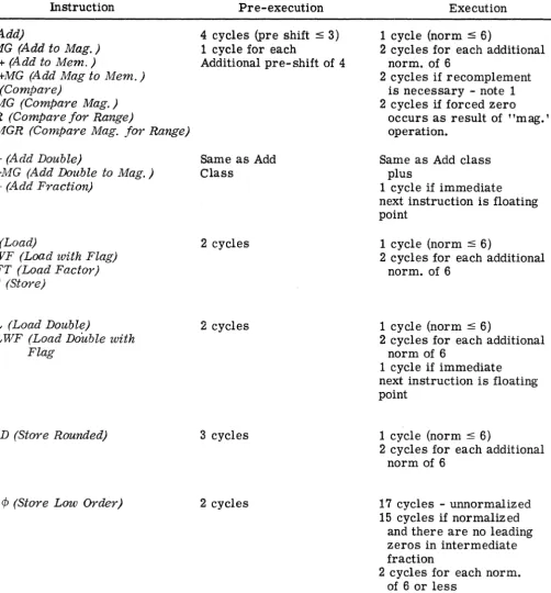
Floating Point Instruction Times
Following is a summary of "raw" floating point execution. The
times are predicated upon the availability of data and instructions when
needed; that is, the times given are the maximum speed at which the
floating point unit may operate. If some memory access (look-ahead,
I-box, etc.) factors enter such that data and instructions are not
avail-able when the floating pOint unit is avail-able to accept them (or requires
them), the extra delay thus caused is added to the times below.
The times are broken up into two types of cycles: pre-execution
and execution, defined as follows:
• Pre-Execution - That part of the instruction which may be
executed before any modification of an addressable register
occurs. Floating point instructions are begun as soon as
data paths are free and the instruction and initial addressed
operand is made available. This time will overlap checking
of a previous instruction, indicator setting, interrupt testing,
memory storage, etc. These cases may lead to a condition
such that the operation should never have been started
case the pre-execution is terminated and no addressable
registers would be modified. (As far as programmer is
con-cerned pre-execution never occurred.)
• Execution - The part of the instruction which follows the
initial modification of an addressable register up to the point
when the next floating point instruction may begin.
The times are listed (table 2) in terms of the basic machine cycles,
TABLE 2. FLOATING POINT INSTRUCTION TIMES
Instruction
+ (Add)
+ MG (Add to Mag. ) M+ (Add to Mem.)
M +MG (Add Mag to Mem.)
K (Compare)
KMG (Compare Mag. ) KR (Compare for Range)
KMGR (Compare Mag. for Range)
D+ (Add Double)
D+MG (Add Double to Mag. )
F + (Add Fraction)
L (Load)
L WF (Load with Flag) LFT (Load Factor) ST (store)
DL (Load Double)
DLWF (Load Double with Flag
SRD (store Rounded)
SL ¢ (Store Low Order)
Pre-execution
4 cycles (pre shift :s 3) 1 cycle for each
Additional pre-shift of 4
Same as Add Class
2 cycles
2 cycles
3 cycles
2 cycles
Execution
1 cycle (norm :s 6)
2 cycles for each additional norm. of 6
2 cycles if recomplement is necessary - note 1 2 cycles if forced zero
occurs as result of "mag." operation.
Same as Add class plus
1 cycle if immediate next instruction is floating pOint
1 cycle (norm :s 6)
2 cycles for each additional norm. of 6
1 cycle (norm :s 6)
2 cycles for each additional norm of 6
1 cycle if immediate next instruction is floating point
1 cycle (norm :s 6)
2 cycles for each additional norm of 6
17 cycles - unnormalized 15 cycles if normalized
and there are no leading zeros in intermediate fraction
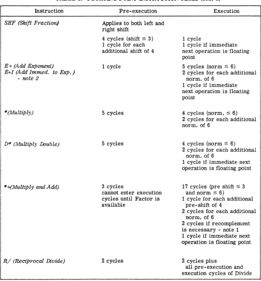
[image:21.617.60.563.166.706.2]TABLE 2. FLOATING POINT INSTRUCTION TIMES (cont'd)
Instruction
SHF (Shift Fraction)
E+ (Add Exponent)
E+1 (Add 1mmed. to Exp.)
- note 2
*(Multiply)
D* (MuUiply Double)
*+(Multiply and Add)
R/ (Reciprocal Divide)
Pre-execution
Applies to both left and right shift
4 cycles (shift ~ 3)
1 cycle for each additional shift of 4
1 cycle
5 cycles
5 cycles
3 cycles
cannot enter execution cycles until Factor is available
2 cycles
Execution
1 cycle
1 cycle if immediate next operation is floating point
5 cycles (norm ~ 6)
2 cycles for each additional norm. of 6
1 cycle if immediate
next operation is floating pOint
4 cycles (norm. ~ 6)
2 cycles for each additional norm. of 6
4 cycles (norm ~ 6)
2 cycles for each additional norm. of 6
1 cycle if immediate next operation is floating pOint
17 cycles (pre shift ~ 3
and norm ~ 6)
1 cycle for each additional pre-shift of 4
2 cycles for each additional norm. of 6
2 cycles if recomplement
is necessary - note 1 1 cycle if immediate next operation is floating point
2 cycles plus
all pre-execution and
[image:22.613.46.572.143.708.2]TABLE 2. FLOATING POINT INSTRUCTION TIMES (cont'd)
Instruction
/(Divide)
D/ (Divide Double)
SRT (Store Root)
Pre-execution
2 cycles (divisor shift :5 6)
2 cycles for each additional divisor shift of 6
If zero divisor
3 cycles pre-execution and
Same as Divide
2 cycles
Execution
2 cycles (dividend shift ~ 6)
2 cycles for each additional dividend shift of 6 or total of
3 cycles if dividend is all zero
2 cycles for initial reduction loop if dividend is normalized
3 cycles for initial dividend pass if dividend has leading zeros.
2 cycles for each additional reduction loop (number of cycles is data dependent).
2 cycles if final remainder has to be complemented
1 cycle - all
2 cycles execution instead of previous
Same as Divide
plus
6 cycles (remainder norm :s 6) 2 cycles for each additional remainder norm. of 6
106 cycles (norm. :s 6) 1 cycle if operation began with a "B" pulse
[image:23.620.56.592.158.728.2]NOTE 1 - When fraction signs are unlike, the operand which is
pre-shifted will be complemented. Recomplementing will only
occur if the complemented (following pre-shift) fraction is larger in magnitude than unshifted fraction.
If fraction signs are alike no complementing occurs.
NOTE 2 - Add Exponent and Add Immediate to Exponent will most
likely be ctanged in the near future to three pre-execution and three execution cycles.
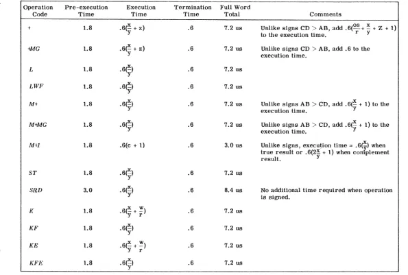
Serial Arithmetic Execution Times
The execution times of SAU instructions can be presented in terms of some basic equations shown in table 2 below.
The column headings are defined as follows:
.• Operation Code - instruction abbreviations.
• Pre-execution Time - time required to decode operation and set up controls.
• Execution Time - time required to perform the instructed function.
• Termination Time - time required to set indicators and clear unit.
• Full Word Total - a computed time in microseconds for the operations using unsigned full word operands which produce no arithmetic carries.
• Comments - variations or additions to the execution time
equations.
All equations were developed for unsigned operations. Signed operations can be computed by adding. 6 microseconds to the
pre-execution time. An additional .6 microseconds must be added if the
result of the· operation requires complementing. The following
opera-tions require no additional time when signed: SRD,
e,
eM, CT, CV,t.¢
TABLE 3. EQUATIONS FOR SAU TNSTRUCTIONS ~
~ ...
I
Operation Pre-execution Execution Termination Full WordCode Time Time Time Total Comments
+ 1.8 .6(~ + z) .6 7.2 us Unlike signs CD > AB, add .6(os + ~ + Z + 1)
to the execution time. r y
+MG 1.8 .6(-x + z) .6 7.2 us Unlike signs CD > AB, add .6 to the
y execution time .
L 1.8 . 6(~) .6 7.2 us
y
LWF 1.8 .6(~) .6 7.2 us
y
M+ 1.8 .6(~) .6 7.2 us Unlike signs AB > CD, add .6(~ + 1) to the
y
execution time. Y
MtMG 1.8 • y 6(~) .6 7.2 us Unlike signs AB > CD, add .6(~ + 1) to the
execution time. Y
M+l 1.8 .6(c + 1) .6 3.0 us Unlike signs, execution time = .6(Y) when
true result or .6(2~ + 1) when complement
result. Y
ST 1.8 .6(~)
Y .6 7.2 us
SaD 3.0 .6(~) .6 8.4 us No additional time required when operation
Y is signed .
K 1.8 . 6(~ + ~) .6 7.2 us
Y r
KF 1.8 .6(~) .6 7.2 us
Y
t.¢
KE 1.8 x w .6 7.2 us
I .6(-+-)
..::J Y r
KFE 1.8 .6(~)
[image:25.791.71.667.103.504.2]w
TABLE 3. EQUATIONS FOR SAU INSTRUCTIONS (cont'd)
'---..
ex:>
'---..
CJ')
[image:26.793.67.673.101.506.2]I Operation Pre-execution Execution Termination Full Word
...
Code Time Time Time Tolal Comments
KR 1.8 .6(y + x r) w .6 7.2 us
KFR 1.8 .6(~) .6 7.2 us
y
C 1.8 • y 6(~) .6 7.2 us
CM 1.8 .6(~) .6 7.2 us
y
CT 1.8 .6(~) .6 7.2 us
y
LTRS 2.4 .6(~ + 3) .6 9.6 If the effective FL is greater than 48 bits,
y
add .6(t -1) to the execution time. 8
LFT 2.4 .6(~) y + 3) .6 9.6 If the effective FL is greater than 48 bits,
then add .6(k -1) to the execution time .
B-D 2.4 . 6(x + ~ + 1) .6 45.3
LCV
D-B 2.4
.6(~+i+~+4)
.6 14.7LeV
B-D 2.4 .6(x + 3) .6 29.4 If the converted field length is greater
LTRCV than 48 bits, add .6(~~ -1) to the
execution time .
D-B 2.4 . 6(~ + 16) .6 21.6 If the field length to be converted after all
LTRCV zone bits have been removed is greater
w tilan 48 bits, add .6(~ -1) to the execution
I time.
ex:>
B-lJ 2.4 .6(s +
g
+ 1) .6 37.2CA) ~ '-.. C»
...
CA) I co Operation Code B-D DCV D-B CV D-B DeV'"
'" +
/
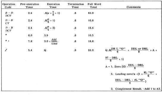
TABLE 3. EQUATIONS FOR SAU INSTRUCTIONS (cont'd)
Pre-execution Execution
Time Time
2.4 .6(s + u 8" + 1) 2.4 .6(4 s + 1) 2.4 .6(4" s + 2)
6.0 3.9
7.8 3.0 + Add exec. time
5.4 Q
Termination Full Word
Time Total
.6 63.0
.6 10.8
.6 18.6
.6 10.5
.6 18.6
.6 24.0
Comments
DR L "0" DDL or DRL
Q . 6 ( , . + + A +
97 - DRL
x + 1)
A = 1. Zero DD _DDL - DRL 6
#L "0"
2. Leading zero's -(1 + _ +
DDL - DRJ: - #L "0" )
[image:27.791.107.652.141.463.2]Glossary of Terms
DD DR DDL DRL
L "0"
#L "0" DDL or DRL
os
FL BS B-D D-B R S T U V Wx
yz
c
Dividend Divisor Dividend length Divisor lengthLeading zero IS
Number of leading zero's
Dividend or divisor length which ever is greater
Offset Field length Byte size
Binary to decimal Decimal to binary
8 in Binary - 4 in decimal
Accumulator field specified by the offset minus all leading zero's
Field length less all zone bits Result field
96 in binary - 92 in decimal
The number of accumulator significant bits greater than the field length
Field length in unsigned operations - field length minus the byte size in signed operations 8 in binary operations and byte size in decimal
operations x
One for a carry out of the last - byte plus one for a carry out of each succeeding 8 bit byte in binary or 4 bit byte in decimal
The number of times a carry results from an 8 bit byte in binary or a 4 bit byte in decimal
Timing of I-Box Instructions
The following tables list the I-box times for decoding for
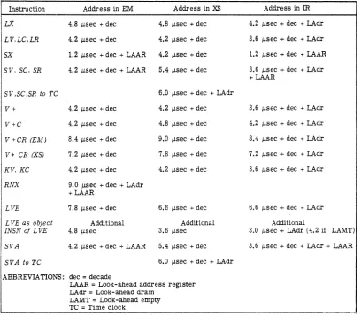
TABLE 4. I-BOX TIMES - DIRECT INDEX
Instruction Address in EM Address in XS Address in m
LX 4.8 IJ.sec + dec 4.8 IJ.sec + dec 4.2 IJ.sec + dec + LAdr
LV,LC.LR 4.2 j.Lsec + dec 4.2 IJ.sec + dec 3.6 IJ.sec + dec + LAdr
SX 1.2 IJ.sec + dec + LAAR 4.2 j.Lsec + dec 1.2 j.Lsec + dec + LAAR
SV. SC. SR 4.2 IJ.sec + dec + LAAR 5.4 IJ.sec + dec 3.6 IJ.sec + dec + LAdr +LAAR
SV .SC .SR to TC 6.0 j.Lsec + dec + LAdr
V+ 4.2 IJ.sec + dec 4.2 IJ.sec + dec 3.6 IJ.sec + dec + LAdr
V+C 4.2 IJ.sec + dec 4.8 IJ.sec + dec 4.2 IJ.sec + dec + LAdr
V +CR (EM) 8.4 IJ.sec + dec 9.0 j.Lsec + dec 8.4 IJ.sec + dec + LAdr
V+ CR (XS) 7.2 IJ.sec + dec 7.8 IJ.sec + dec 7.2 IJ.sec + dec + LAdr
KV,KC 4.2 IJ.sec + dec 4.2 IJ.sec + dec 3.6 IJ.sec + dec + LAdr
RNX 9.0 j.LSec + dec + LAdr +LAAR
LVE 7.8 j.Lsec + dec 6.6 IJ.sec + dec 6.6 IJ.sec + dec + LAdr
L VE as object Additional Additional Additional
INSN oj LVE 4.8 j.Lsec 3.6 IJ.sec 3.0 IJ.sec + LAdr (4.2 if LAMT)
SVA 4.2 IJ.sec + dec + LAAR 5.4 IJ.sec + dec 3.6 IJ.sec + dec + LAdr + LAAR
SVAtoTC 6.0 IJ.sec + dec + LAdr
ABBREVIA TIONS: dec
=
decadeLAAR
=
Look-ahead address register LAdr = Look-ahead drainLAMT = Look-ahead empty TC = Time clock
TABLE 5. I-BOX TIMES- IMMEDIATE INDEX
Instruction Basic Time Variations
LVI, LCI. LRI. L VNI 2.4 IJ.sec + dec
V + I. V - I 2.4 j.Lsec + dec
V +lC. V - IC
V +lCR. V -ICR
C +1, C - I
KVI. KVNI, KCI
L'VS
3.0 IJ.sec + dec Also V ± ICR where Count'" 0
"7.2 p.sec + dec 1.2 p.sec less if Refill from X5
2.4 JLsec + dec
2.4 j.Lsec + dec
[image:29.612.91.499.143.501.2]TABLE 6. I-BOX TIMES - MISCELLANEOUS INSTRUCTIONS
Instruction Address in EM Address in XS Address in
m
R (from EM) 7.8 J,J.sec + dec + LAAR 7.2 J,J.sec + dec 6.6 J,J.sec + dec + LAAR + LAdr
R (from X S) 5.4 J,J.sec + dec + LAAR 5.4 J,J.sec + dec 4.2 J,J.sec + dec + LAAR + LAdr
RCZ (C ¢ 0) 4.2 J,.Lsec + dec 3.0 J,J.sec + dec 3.0 J,J.sec + dec + LAdr
Z 1.2 J,J.sec + dec + LAAR 3.6 J,.Lsec + dec 1.2 J,J.sec + dec + LAAR
EX 1. Decode time, plus
2. Always begins with Look-ahead drain, plus
3. Instruction fetch time as follows:
Address
0.0, 0.32
1.0, 1.32 2.0, 2.32 3.0, 3.32 4.0, 4.32 5.0 -11.32
12.0, 12.32 13.0 -14.32 15.0, 15.32
16.0 -30.32 31.0, 31.32
32.0 -up
Time
4.8 J,.Lsec
6.0 j.Lsec 7.8 J,J.sec 7.8 J,J.sec 7.8 J,J.sec
11.2 J,J.sec
7.8 J,J.sec
5.4 J,.Lsec
4.8 j..Lsec
4.2 J,.Lsec
6.0 J,J.sec 5.4 J,J.sec
4. Add decode and execution time for given instruction
5. Always ends with LA drain, plus
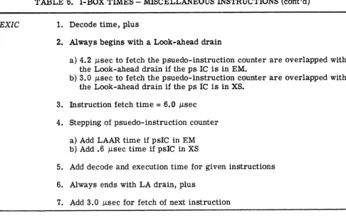
TABLE 6. I-BOX TIMES - MISCELLANEOUS INSTRUCTIONS (cont'd)
EXIC
Instruction
B
BR
BE
BEW
NOP
BD
1. Decode time, plus
2. Always begins with a Look-ahead drain
a) 4.2 J..Lsec to fetch the psuedo-instruction counter are overlapped with
the Look-ahead drain if the ps IC is in EM.
b) 3.0 J..Lsec to fetch the psuedo-instruction counter are overlapped with the Look-ahead drain if the ps IC is in XS.
3. Instruction fetch time
=
6.0 IJ,sec4. Stepping of psuedo-instruction counter
a) Add LAAR time if psIC in EM b) Add .6 IJ,sec time if psIC in XS
5. Add decode and execution time for given instructions
6. Always ends with LA drain, plus
7. Add 3.0 IJ,sec for fetch of next instruction
'TABLE 7. I-BOX TIMES - UNCONDITIONAL BRANCH
Basic Time SIC to EM
3.6 IJ,sec + dec 4.8 IJ,sec + dec + LAAR
4.8 IJ,sec + dec 6.0 IJ,sec + dec + LAAR
3.6 IJ,sec + dec + LAdr 4.8 IJ,sec + dec + LAAR +
(if previously disabled) LAdr (if previously
dis-abled)
Setup time as above on BE
1.2 IJ,sec + dec
4.8 IJ,sec + dec +
2 LA drains
Same as Basic
6.0 IJ,sec + dec +
2 LA drains
SIC to XS
4.2 IJ,sec + dec
5.4 IJ,sec + dec
4.2 IJ,sec + dec
+ LAdr (if
pre-viously disabled)
Same as Basic
5.4 IJ,sec + dec +
[image:31.617.89.576.141.444.2]TABLE 8. I-BOX TIMES - INDEX BRANCHES
Instruction Basic Time SIC to EM SIC to XS
CB (Successful) 4.2 J.,Lsec + dec 6.6 J.,Lsec + dee + LAAR 7.2 J.,Lsec + dec
CB (Unsuccessful) 3.6 J.,Lsee + dec 3.6 J.,Lsec + dec 3.6 J.,Lsec + dec
CBR (EM) (Succ) 6.6 J.,Lsee + dec 9.0 J.,Lsec + dec,+ LAAR 9.6 Ilsec + dec
CBR (XS) (Succ) 6.0 J.,Lsec + dec 8.4 J.,Lsec + dec + LAAR 9.0 J.,Lsee + dec
CBR (EM) (Unsucc) 6.0 J.,Lsee + dec 6.0 J.,Lsee + dec 6.0 J.1.sec + dec
CBR (XS) (Unsucc) 5.4 J.,Lsec + dec 5.4 J.,Lsee + dec 5.4 J.,Lsec + dec
NOTE: CBR behaves like CB if Refill is not to be taken.
Ex: CBR, branch on eount -I- zero
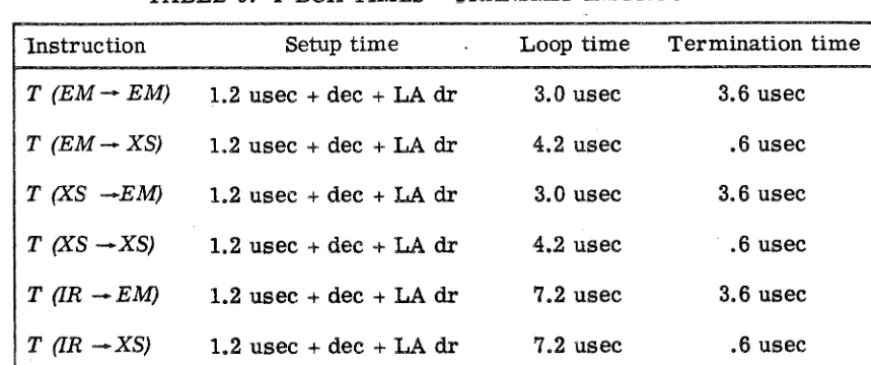
TABLE 9. I-BOX TIMES - TRANSMIT INSTRUCTIONS
1nstruction Setup time Loop time Termination time
T (EM-EM) 1.2 usee + dee + LA dr 3.0 usee 3.6 usee
T (EM-XS) 1.2 usee + dec + LA dr 4.2 usee .6 usec
T (XS -EM) 1.2 usec + dee + LA dr 3.0 usee 3.6 usee
T (XS -XS) 1.2 usee -+ dec + LA dr 4.2 usee .• 6 usee
T (IR-EM) 1.2 usee + dee + LA dr 7.2 usee 3.6 usee
T (IR -XS) 1.2 usee + dec + LA dr 7.2 usee .6 usee
[image:32.621.72.563.169.382.2] [image:32.621.102.538.436.618.2]TABLE 9. I-BOX TIMES - TRANSMIT INSTRUCTIONS (cont'd)
Instruction Setup time Loop time Termination time
S (EM-EM) 1.2 usec + dec + LA dr 6.0 usec 1.8 usec
S (EM-XS) 1.2 usec + dec + LA dr 6.6 usec 1.8 usec
S (EM -IR) 1.2 usec + dec + LA dr 9.6 usec 1.8 usec
S (XS -EM) 1.2 usec + dec + LA dr 6.0 usec 1.8 usec
S (XS -XS) 1.2 usec + dec + LA dr 7.2 usec 1.8 usec
S (XS -IR) 1.2 usec + dec + LA dr 10.8 usec 1.8 usec
S (IR -EM) 1.2 usee + dec + LA dr 9.6 usee 1.8 usec
S (IR -XS) 1.2 usec + dec + LA dr 10.2 usec 1.8 usec
S (IR -IR) 1.2 usec + dec + LA dr 15.0 usec 1.8 usec
Note: The immediate/direct and the forward/backward options do not affect the timing of either transmit or swap.
Analysis and Interpretation of the New Speeds Relative Machine Environment
Machine Organization
In conventional machines the instruction time is dependent upon the
total length and delays along information paths, and the hardware places a
severe limitation on performance.
The organization of the 7030 has been devised to free the machine from
such limitations. To a large extent, the number of obstacles along the
in-formation path is not of crucial importance; the speed and performance of
the machine is governed by the average frequency of information access.
For example, a 7030 box has a readout time of 1 fJ.S and a recycle time of
2.2 fJ.s, yet in the 7030 system information can be obtained at the rate of
[image:33.620.110.542.156.414.2]The 7030 system organization is characterized by the local autonomy
of the major units: the memory bus control unit (MBCU), the I-box, the
look-ahead (LA), the E-box, the exchange, and the disk exchange. (For
defi-nitions of these terms the reader is referred to Appendix A.)
Each major unit is responsible for processing at top speed as long as
there is data to process. The local autonomy of the MBCU, exchange, and
disk exchange means that the central processing unit (CPU) can operate
in-dependent of I/O operations. Within the CPU this local autonomy means
that temporary delays up to several J.,LS in one unit can be tolerated without
slowing down the entire pipe line. Extensive buffering of information is
needed to absorb such temporary delays, and within the 7030 CPU at any
given time up to ten instructions can be in various stages of processing.
Within wide limits, the times for instruction processing is not the sum of:
Instruction fetch, instruction error check, decoding, operand fetch,
oper-and error check, oper-and execution but is the maximum of these times
aver-aged over several instructions.
The E-box times of the instructions listed in the previous section
are the times realizable if the LA levels (which are buffers to the E-box)
can always supply needed information to the E-box. The machine
organi-zation is such that this is usually the case.
For such a loosely-coupled machine the information paths are
ac-tually longer and the number of obstacles larger than conventional
tighUy-organized machines. It is possible to create situations to make the
infor-mation path time influence instruction time. All of these situations, so
far as the CPU is concerned, have an effect on the LA buffering, which in
Effect of Memory Interleaving
With the instruction buffers 1 Y, 2Y (capable of housing four
half-word instructions), in the I-box, and the four LA levels, the advantage
of memory interleaving is fully exploited.
The demand of the E -box on LA is usually no higher than one word
per 1.5 J..LS (sequence of floating adds) and on the average, the memory is
not a factor. In terms of the four-level look-ahead, the requirement is
satisfied if any four E-box demands are fulfilled in 6 J..Ls. The zremory
interleave scheme allows four words every 2.2 J..LS (four box interleaving)
or four words every 4.4 J..Ls (two box interleaving).
In actual computations, with the instructions occupying the two lower
memory boxes and data occupying the four upper memory boxes, memory
conflict is not expected to be an important factor, even if the I/O units are
in full operation. Delays due to repeated demands of the same memory
box are expected to be quite infrequent.
There are conflicts due to fetches and stores, independent of
mem-oryaccess. These are related to the machine measures at preserving
the logical integrity of a program sequence and will be discussed
else-where.
Over lapping of Decoding
The I-box decoding, addr-ess indexing, and operand request continues
as long as instructions are available and as long as LA levels are
avail-able for loading. For a sequence of floating point instructions the decoding
rate is one instruction per 1.2 J..LS. With few exceptions, this is faster than
the execution rate. Thus the decoding time for average floating point
se-quences is completely overlapped by concurrent E-box execution time. In
other words, floating point instructions are E-box limited. Address
VFL instruction decoding is much more complicated. The minimum
time is 3.6 ).J..S which includes the loading of two LA levels. Each addition
level requires an additional 0.6 ).J..s,andeach indexing operation requires 0.6
).J..s. Of course, there may be further slow down in the decoding process
if the LA levels are not available for loading, or if the second half of the
instruction is not available when needed.
The decoding time of I-box instructions is 0.6 (J.S. Since these
in-structions are executed in the I-box, the decoding time has been included
in the execution times. The processing time of I-box instructions can be
largely overlapped by concurrent E-box action, since their E-box time, is
only 1.2 ).J..S.
Whenever a branch instruction is successfully executed, the
pre-fetched instructions in 1 Y, 2Y must be replaced by new instructions. The
latter have to be checked prior to use, and the decoding of the next
instrue-tion will be delayed. This delay has been taken into account in the timing
given. Again, concurrent E-box action can overlap much of this.
Look-Ahead Levels
In order to use the look-ahead (LA) levels efficiently, they must not
be allowed to be empty over extended lengths of time, nor should they be
crowded with data with little information content.
The following instructionaemptythe LA completely: T, T]. SWAP,
SWAP], RNX, BD,
All I-box instructions load LA levels for index register recovery
or for indicator register updating. These levels are not useful to the
E -box and have the effect of reducing the number of LA levels.
VF L data with word boundary crossover represent inefficient use of
Frequent demands on LAAR (such as in consecutive STORE
instruc-tions)and prolonged decoding delays in the I-box in general often lead to a
half-empty look-ahead.
When the number of effective LA levels are reduced, the E -box may
become idle. The I-box processing time can then no longer be absorbed.
The I-Checker
The I-Checker is shared between the I-box and LA. It processes
in-formation in 0.6 /lS and is used for the following functions:
1. Instruction word error check with concurrent ECC to I-i>arity
conversion.
2. I-box data error check with concurrent ECC to I-parity
conver-sion.
3. Passage of data and VFL operation code from I-box to LA, with
concurrent I-parity to LA-parity conversion.
4. E -box fetch operand error check and check code conversion.
5. Store operand error check and check code conversion.
6. As part of data path between LA and I-box during, say, branch
recovery.
7. As part of I -box internal data path.
8. As part of LA internal data path.
The great majority of the demands on the I-Checker is due to 1,2,
3, 4, and 5 above. It is therefore conceivable that I-Checker conflicts may
occur. The situation has not been completely studied (because of the
dif-ficulty in subjecting the variables to program control), but it does not seem
to have had much effect on floating point operations. When an I-Checker
conflict occurs, the processing of one piece of data may have to be delayed
The LAAR, Stores and Internal Operand Fetches
All "to-memory" operations involving the main memory from the
7030 CPU are prepared by the I-box and accomplished by the look-ahead.
I/O stores are, however, performed directly between the MBCU and
ex-change units.
The look-ahead address register (LAAR) is created for the purpose
of containing the store address. LA levels are made available for the store operand.
In the case of I-box store type instructions (SX, SV, SC, SR, SVA,
R, RXZ, T, SWAP, etc.) the store operands are already available during
I-box processing time and can be converted to ECC check bits during
shipment to LA, simplifying the store action in LA. In practically all other cases the store operand will not be available during I-box
proc-essing. In any case, the LAAR will remain "busy" from the time of
look-ahead loading until the proper operand is available, is fetched,
checked, and accepted by the MBCU.
In an instruction, the address may refer to the main memory,
in-dex register storage, or an internal register. The I-box, upon decoding
an instruction whose fetch operand is an internal register, uses the
LAAR to store the internal operand address. This is because the needed
operand is not available during the decoding stage, and the mechanism
for internal operand fetch already exists for the handling of store
instruc-tions. Unlike a standard store, no memory bus request is needed, and the
LAAR is freed sooner.
(By an internal operand address is meant address 3, or an address
between 5 and 12 inclusive. SZ, SlA, 5MB, and SRM, SFT and STR are
bona fide main memory locations. SIT , STC and SO through S15 are in
Since there is only one LAAR, if the latter is busy whenever the
I-box decodes an instruction requiring LAAR, a wait must occur until the
LAAR is free for reloading. Therefore, LAAR-requiring instructions
should preferably be reasonably far apart, ideally with three or more
time consuming instructions in between to ensure smooth I-box decoding.
Measurements on consecutive floating-point-to-memory operations (ST,
MT, LFT, etco) do not therefore yield realistic timing information. On
the other hand, the placement of such instructions is usually beyond the
programmers control.
A store into index storage is a time-consuming operation.
When-ever such an instruction is decoded, since the next instruction may make
use of the new index contents, the I -box does no further decoding until the new index contents arrives.
Store Close to Fetch
Whenever I-box requests a memory fetch, a comparison is made
with the contents of LAAR to avoid logical conflicts. In all cases,
logi-cal conflicts will not produce wrong results, although some delays are to
be expected.
One such conflict is a store into a location corresponding to a
pre-fetched instruction, such as in the sequence:
A ST(u), A +.0.32
*
+ (n), 1000. (Sl5) (1)The second instruction, having been previously fetched into 1 Y
or 2 Y, clearly cannot have the correct information until the store is
complete. When such a store is decoded, I-box invalidates the prefetched
Another conflict is a store into a nearby I-box operand address:
ST (u), 1003. ($12)
V +, $15, 1003. ($12) (2)
The execution of the second instruction is delayed until the correct
operand arrives.
A third such conflict is a store into a nearby E -box operand address:
ST (n),
*
(n) ,1007.
1007. (3)
The I -box comparison with the LAAR shows that the operand will be
in the LA prior to its arrival at the memory. A forwarding mechanism
is activated to make the store operand available to the fetch level. Further
LA loading in the I-box is delayed until the forwarding is completed.
Forwarding is available also for consecutive fetch of the same
mem-ory operand. Whenever a fetch-type instruction is decoded, the fetch
ad-dress is gated into LAAR unless the latter is busy. This act does not
make LAAR busy but can allow the forwarding on successive fetches.
I-box Instructions
The instructions executed by the I-box can largely be absorbed in an
E-box limited environment. The follO\\"ing points, however, are to be noted:
1. Some I-box instructions require the emptying of the LA.
Con-current E-box operations would not be possible.
2. Each I-box instruction results in one (sometimes more) level
of LA being loaded. This is done to enable the convenient
up-dating of certain indicators and to allow interruption action (if
needed) to take place in step with other interruptions. The
contents of an index register to enable the restoration in case of
unexpected interruptions. It takes 0.9 to 1.2 p.s to process an
LA level corresponding to I-box instructions. This time cannot
be overlapped by concurrent E-box action.
3. 'Fhe E-box overlapping cannot be effective unless I-box
instruc-tions are well dispersed.
4. I-box operand fetches are made when the instruction is decoded.
There is no look-ahead buffering to reduce the effective fetch
time. I-box immediate instructions, not requiring memory
ac-cess, are therefore faster than the "direct index arithmetic
in-structions I I .
5. Some I-box instructions require more than one memory
refer-ence.
6. All successful branch instructions require the fetch of new instructions.
The instructions previously buffered into 1 yand 2Y are invalidated.
7. The treatment of some conditional branches requires extensive
E-box action and will be discussed in the next section. The
fol-lowing branches, however, involve conditions known to the I-box
and are executed entirely within the I-box:
CB and variants
Bind for XF. XVLZ. XVZ. XVGZ. XCZ, XL, XE. XH.
Recovery Action
The I-box is usually ahead by several instructions during a machine
run of the E-box. There are certain situations, however, which may
force the I-box to refer to the same instruction as the E-box:
1. "Wrong branch" recovery, the I-box having made a wrong
assumption about the path to be chosen on conditional branch.
These cases may require the I-box to move backwards in time to
be in step with the E-box. All changes in the index registers and/or
:ndex indicators due to the advance processing by the I-box must now
be undone.
For conditional branches where the condition is unknown to the
I-box, the latter assumes the branch to be unsuccessful (to avoid
unnec-essary invalidation of 1 Y, 2 Y contents) and processes ahead. Steps are
taken, however, to perform the actual test and to facilitate the
alterna-tive path to be taken. Altogether four LA levels are used for each such
branch instruction: three levels not unlike those for a VF L
connect-to-memory instruction plus a branch recovery level. It is noted that there is always a store type level, whether the programmer specifies a change
of the tested bit or not. For Bind, two of these four levels involve the
LAAR.
When the I -box guess proved correct, no particular action is taken
aside from setting of the tested bit. If, however, the guess proved
incor-rect by E-box arithmetic, the I-box has already processed ahead, and
re-covery action has to be taken to ensure the logical integrity of the
pro-gram. The re-setting of the I-box to the previous state of ten requires
shipment of index register information back to the I-box. The correct
instruction counter value is also shipped back to the I-box.
The interruption action is quite similar to branch recovery except
4
Computational Performance
MATRIX INVERSION - GERB2
Problem
The inversion of Hilbert matrix segments of increasing size, using
Jordan's elimination method. In each case the determinant of the matrix
is evaluated as a by-product.
Program
See Volume 2.
Timing
10 x 10 matrix 0.02 seconds
20 x 20 matrix 0.14 seconds
30 x 30 matrix 0.43 seconds
40 x 40 matrix 0.99 seconds
50 x 50 matrix 1.S9 seconds
60 x 60 matrix 3.23 seconds
70 x 70 matrix 5.10 seconds
SO x SO matrix 7.55 seconds
90 x 90 matrix 10.69 seconds
100 x 100 matrix 14.61 seconds
Comparison With Other Machines
The 96K memory allows the convenient inversion of matrices up
to 300
x
300 without using drums or tapes. The extra word length isalso an asset in inversion. The present program uses the relatively
Hilbert matrices are extremely ill-conditioned, and no claim is
made about the accuracy of the 100 x 100 inversion result. For an
or-dinary matrix of size beyond 40 x 40, it is probably fair to say 27
frac-tion bits (as in the 7090) would not be adequate. Double precision cost
is a 6-fold decrease in speed on the 7090. The 7030 with 48 fraction bits
is adequate for a much larger range.
Additional Remarks
There is a faster matrix inversion program which gives the
follow-ing results:
50 x 50 matrix
100 x 100 matrix
150 x 150 matrix
200 x 200 matrix
250 x 250 matrix
300 x 300 matrix
1.1 seconds
10 seconds
31 seconds
79 seconds
144 seconds
250 seconds
A 128 x 128 linear equation program with two sets of unknowns requires
8.6 seconds.
There is also a double preCision version of GERB2, called GERB3,
with the following speeds:
10 x 10 matrix
20 x 20 matrix
30 x 30 matrix
40 x 40 matrix
50 x 50 matrix
0.05 seconds
0.41 seconds
1.36 seconds
3.19 seconds
6.21 seconds
It is seen that the double preCision computation time is roughly triple
that of single precision. 7030 double precision is almost equivalent to
MATRIX MULTIPLICATION - MXM16
Problem
Multiplication of two nxn matrices.
Program
Listing (including test program) are included in Volume 2.
Assume n = 17 k+m. A "major" inner loop is traversed k times, then a short inner loop is traversed m times, for each vector
multiplica-tion.
The matrix elements used for the test are all equal to normalized
floating point 1.0 and are placed in the upper memory (32768.0 and beyond).
Timing
25 x 25 matrices
50 x 50 matrices
0.20 seconds
1.35 seconds
75 x 75 matrices 4.74 seconds
100 x 100 matrices 10.71 seconds
125 x 125 matrices 21.44 seconds
Additional Remarks
A simple version (taken directly from the 7030 programming
ex-ample book) requires 15.5 seconds for 100 x 100 matrices. The timing
cost was traceable to the use of the more accurate but relatively slow
LFT; *+ sequence and the fact that two adjacent I-box instructions are
executed for each traversal of the inner loop.
In the present program the ratio of I-box instructions to arithmetic
instruction is greatly reduced, but no other attempt has been made to
PRIME NUMBER GENERATION PROGRAM PRIMe
Problem
To generate prime numbers by the sieve of Eratosthenes, using
VFL arithmetic and automatic program interruption.
In a very large memory segment (octal 17740.40 through octal
272777.63), consecutive bits represent consecutive odd integers. The
bit at distance d from the beginning of the string thus represents the
odd number 2d + 1. In the beginning all bits in the string are set to l's.
A working prime P is represented by a 1 bit to the right of the
previous working prime. In the beginning the first working prime is 3,
oc~~ying._tg~ s_e.C:Qn~Ll?Jt .CJL~h~bit sequence .
...
The bits representing the number p2 + np, n
=
integer~
0, aresystematically made zero by what appears to be an infinite loop, starting
from the case n
=
O. When the prescribed upper memory boundary isexceeded, an interruption causes exit from the loop. The next working
prime is then found, and the process is repeated, unless an end condition
is encountered. The end condition is met when, for a working prime p,
the bit corresponding to p2 lies beyond the upper boundary. the
non-zero bits remaining in the interval represent prime numbers if the first
bit is reinterpreted to represent the even prime number 2.
Program (See Volume 2)
It is to be noted that 2/3 of the program consists of an
interrup-tion table.
Timing-106.7 Seconds
_ The largest prime is (52,307,665)8' or about 11 million. A slight
change in the inner loop (replacing the progressive indexing by ordinary
Comparison With Other Machines.
The 7030 machine can process bits very conveniently. Each
bit zeroing on the 7030 takes only one instruction. The corresponding
operation on the 7090 or similar machines requires very careful
programming and relatively long computation time (about 48 f,J.s), even
if only 25 = 32 bits are used per word to avoid a divide instruction.
Also, other machines do not have as many bits in the memory. For
this problem, the memory capacity of the 7030 is almost six times the
7090.
A MONTE CARLO PROGRAM
Problem
The physics and method of solution of the problem is described by
Davis, Journal of Applied Physics, 1960. The original problem was coded
in Livermore on the 709 and 7090.
Briefly, the problem is the passage of particles through a
right-angle bent pipe of circular cross-section at such a low density that only
wall collisions are important. It is assumed that the angle of rebound
is random and uncorrelated with the angle of incidence. The two ends
of the pipe are each divided into 4 areas, and statistics are accumulated
to determine the distribution of exit areas as a function of entry areas.
The calculation on the 7090 differs in one respect to that
de-scribed in the paper. The calculation of random input angles and
re-bound angles follows the "cosine law" • The choice of these angles in
the 7030 code differs from the 709 in method but not in result.
A point is chosen from a uniform distribution in the rectangular
parallelopiped (-0.7, 0.7) x (-0.7, 0.7) x (0.0, 1.0). Unless
2 2 22
the point is discarded and a new one is tried. If the inequality is
satisfied the vector is used as a velocity vecotr relative to the X- Y
waLL
Program
See Volume 2.
Timing
10,000 particles were run and the measured time was 33 seconds.
This is to be contrasted with a known 709 run of 5000 particles in 10
minutes.
For the machine run 20 cards had to be loaded and 36 numbers
were printed on line.
WEATHER FORECASTING STUDY
The following weather forecasting study summarizes the results,
to date, of timing experiments performed on STRETCH.
Inner Loop
This program steps in time one floating-point meteorological
vari-able at one ground point (i, j) of grid, and four floating-point meteorological
variables at each vertical k-level above the ground point. The equations
are non -linear integro- diff erential.
1. First form (AO, see below), lower memory: 6.4 ms.
2. Pseudo j-level (see below), lower memory: .7 ms.
3. AO, upper memory: 6.13 ms.
5. Second form (A1, see below), lower (instructions) and upper
(data) memory: 5.57 ms.
6. Al Modified (see below), lower (instructions) and upper (data)
memory: 7.045 ms.
7. Third form (A2, see below), lower (instructions) and upper
(data) memory: 7.0135 ms.
The above times for runs 1, 3, 4, 5 are for one pseudo j-level,
two i-levels, and three k-levels per i-level. The time for run No.2 is
for one pseudo-j-Ievel only, and the times for runs Nos. 6 and 7 are for
greatly reduced pseudo-j-level, one i-level, and nine k-levels.
AO: Coding prior to any changes for timing improvement.
A1: Same as AO except for coding changes to improve timing
with respect to accumulate multiply, division, add to
memory, separation of indexing instructions, loop entry,
CNOP, one-word transmits, and associated minor changes.
A2: Same as A1 Modified except for additional coding changes
to improve timing with respect to spacing of store
instruc-tions, and more-than-one-word transmits.
Summary
With respect to run No.1, the above times provide the following
approximate improvements: Run No.3 - 4.2 percent; run No.4 - 6.6
percent; run No.5 - 13 percent. With respect to run No.6, run No.7
provides an approximate improvement of .4 percent. This last suggests
that this program is insensitive to the space of the store instruction and
Grid Parameter s
The execution of this program constitutes a neglible part of
execu-tion time required for the Weather program. Also, the program performs
a very specialized function, arising from the particular grid-geometry
and interpolation chosen for the Weather Project. Consequently, no coding
changes in grid parameters were made for purposes of timing
improve-ment or further study. Grid parameters computes, as a function of the
grid size (parameter N), certain grid measurements and interpolation
data (VFL and floating-point).
Using N