“Review on power factor correction by using
Microcontroller”
Prof.R.B.Pandhare1, Mr.V.S.Shelke2, Mr.G.B.Tangade3, Mr.A.V.Pawar4, Ms.A.Kothale5 Department of Electrical Engineering1, 2, 3, 4,5, faculty of Electrical Engineering1
Students of Electrical Engineering2, 3, 4, 5
Email:[email protected],[email protected]
Abstract-In the industrial sector the various motoring loads are continuously running and increasing the inductive load. So the power factor in this system get reduces due to the inductive reactive power. But the electricity board has a standard limit regarding the power factor values and if the power factor goes below the specified limit the electricity company charges the penalty to the industrial consumers. APFC device reads power factor from line voltage and line current by determining the delay in the arrival of the current signal with respect to voltage signal. Capacitor bank added in circuit using relay driver IC .This time values are the calibrated as phase angle and corresponding power factor. If the power factor below 0.8 then capacitor add in circuit. The values of current, power, voltage and power factor are displayed in Liquid crystal display modules. Then the controller calculates the compensation requirement and capacitors are on through relay driver IC accordingly power factor. This is developed by using ATMEGA328controller.
Keywords: APFC, Reactive Power, Power Factor
1. INTRODUCTION
The low power factor leads to the increase in the load current, increase in power loss, and decrease in efficiency of the overall system. Majority of the loads in the industries are highly inductive in nature such as induction motors, AC/DC drives, welding machines, arc furnaces, fluorescent Lightings, electronic controls and computers. There may be a few resistive loads for heaters and incandescent bulbs. Very rarely industries may have capacitive loads such as synchronous motors. Net industrial load is highly inductive causing a very poor lagging power factor. If this poor power factor is left uncorrected, the industry will require a high maximum demand from Electricity Board and also will suffer a penalty for poor power factor. Standard practice is to connect power capacitors in the power system at appropriate places to compensate the inductive nature of the load.In this paper we are using a method of the reactive power compensation by capacitor switching with automatic control using ATMEGA328.
2. LITERATURE REVIEW
2.1 Overview of Previous Research
Work:-A limited number of studies have been attempted on the effect of poor power factor in mines and the corrective measures to mitigate the problem.
Oommen and Kohler (1988) explored the advantages that can be accomplished by proper implementation of power factor compensation. Different compensators along with the sizing and strategic
Location was also considered. A brief study on the economic analysis was carried out to show the economic viability of compensation
Jiang et al. (1993) proposed a novel single-phase power factor correction scheme based on parallel power factor correction concept which was described to be more efficient than convention two-cascade stage
scheme.
Novak and Kohler (1998) pointed out the importance of power factor improvement for technological innovation and advancement in deep coal mine power systems. Different protection equipment to check the inherent electrical faults in the mining system were argued. The power factor correction near loads for improved voltage regulation was emphasized within the constraints of high voltage distribution in underground coal mines
Shwehdi and Sultan (2000) suggested some mathematical calculations for power factor and reactive power requirement of the system along with the capacitor size estimation methods. Different problems associated accompanied by essentials and cautions for capacitor used for correction purpose were discussed in details.
Celtekligil (2008) discussed the application of a method for dynamic power factor correction and voltage regulation in light rail transportation system. Main reactors have been switched on through thyristors using automatic power controllers by sensing the power factor and constantly monitoring the current and voltage, calculating the power factor and switching inductance banks as required. The system proposed connects inductive loads in parallel with the capacitive system to improve the power factor.
Choudhury (2008) gave a design and implementation of a low cost power factor improvement device for small signal low power loads. The design involved designing of a small signal model load, selecting appropriate capacitors, and designing appropriate switching circuits to select proper combination of capacitors.
Shahid and Anwar (2013) offered the design of a power factor improvement circuit using PIC (Programmable Interface Controller) chip with reduced parts count to achieve desired efficiency and low cost. The solution involves ensuring the power factor value from the load and uses an algorithm to determine and trigger switching capacitors in order to compensate for excessive reactive components to increase power factor value
Sharma and Haque (2014) carried out a simulation and analysis study for power factor correction for metal halide high intensity discharge lamps. A modified boost converter using active devices was proposed along with PI controller to stabilize the control loops. The capacitor and inductor with voltage and current ripple with minimum ripple values was designed and to absorb
sinusoidal input current to reduce total harmonic distortion (THD) in the input current with output voltage regulation.
Allah (2016) suggested an automatic power factor correction based on Alienation technique. An alienation technique was developed for calculations of original power factor on-line, active and compensation reactive powers and determination of the required number of capacitor banks to get the desired power factor. Alienation coefficients were calculated between phase voltage and current signals of power supply.
2.2 Background of research work:-
device for improving efficient transmission of active power. If the consumer connect inductive load, then the power factor lags, when the power factor goes below 0.97(lag) then the Electric supply company charge penalty to the consumer. So it is essential to maintain the Power factor below with in a limit. Automatic Power factor correction device reads the power factor from line voltage and line current, calculating the compensation requirement switch on different capacitor banks.
3. POWER FACTOR THEORY
Power factor is the ratio between the active power (kW) to the total apparent power (kVA) consumed by an A.C electrical equipment or a complete electrical installation. It is a measure of how efficiently electrical power is converted into useful work output. The ideal power factor is unity, or one. Anything less than one means that extra power is required to achieve the actual task at hand. A poor power factor can be the result of either a significant phase difference between the voltage and current at the load terminals, or it can be due to a high harmonic content or distorted current waveform.
A poor power factor due to an inductive load can be improved by the addition capacitor of bank, so power factor is also defined as the cosine of the phase difference between current and voltage. It can be mathematically expressed as cosø, where ø is the phase difference between current and voltage. Basically AC power circuits, have resistive loads (like heaters) or inductive loads (like motors) or capacitive loads (like power supplies). Depending upon the loads the current phasor can be in-phase with voltage, lagging the voltage or leading the voltage. For purely resistive load current is in phase with the voltage. Therefore phase difference ø=0˚. Thus giving power factor, cosø=1. Hence the power factor for purely resistive load is unity. In a purely inductive circuit, the current lags the voltage. Therefore the phase difference between current and voltage ø=90˚. Hence power factor is lagging .In a purely capacitive circuit, the current leads the voltage therefore the phase difference between current and voltage ø=90˚.thus the power factor is said to be leading.
3.1 Causes of Low Power Factor
Low Power factor is caused by inductive loads. Inductive loads require the current to create a magnetic field that produces the desired work. The result is an increase in reactive and apparent power and a decrease in the power factor, or efficiency, of a system. Since the power factor is defined as the ratio of KW to KVA, we see that low power factor results when KW is small in relation to KVA. An inductive load includes transformers, induction motors, and induction generators, high intensity discharge lighting. These inductive loads constitute your distribution system. This increase in reactive
power results in large angle between KW and KVA. This large angle decreases the power factor. The efficiency of inductive equipment and system power factor will vary depending on its manufacturer, design, size and age. Most inductive equipment has a nameplate with operating data, including its power factor at rated load.
3.2 Disadvantages of Low Power Factor
Large Line Losses (Copper Losses): Line Losses is directly proportional to the square of current „I2‟ therefore, larger the current, the greater the line losses.
Large kVA rating and size of electrical equipment’s: Power factor is inversely proportional to the kVA i.e. CosФ = kW / kVA Therefore, lower the power factor, the larger the kVA rating of machines also, the larger the kVA rating of machines, the larger the size of machines, the larger the cost of machines. Greater conductor size and cost: In case of
low power factor, current will be increased, thus to transmit this high current, we need the larger size of conductor also cost of conductor increase.
Poor voltage regulation and large voltage drop: Voltage drop = V = IZ. With low power factor, current will be increased. So the larger the current, the larger the voltage drop. In case of low power factor there would be large voltage drop which cause low voltage regulation. Low efficiency: In case of low power factor,
therefore, alternator needs high excitation, thus, generation efficiency would be low. Electrical power supply company imposes a
penalty of power factor below 0.9 lagging in electric power bill.So industries must improve power factor above 0.9.
3.3 Benefits of Power Factor Correction
The advantages that can be achieved by applying the power factor correction are Environmental benefit-reduction of power
consumption due to improved energy efficiency
Reduced power consumption means less greenhouse gas emissions.
Reduction of electricity bills.
Extra KVA available from the existing supply. In transformers and distribution equipment I2R
losses decrease.
In long cables reduction of voltage drop. Extended equipment life- reduced electrical
[image:4.595.68.293.421.744.2]burden on cables and electrical component.
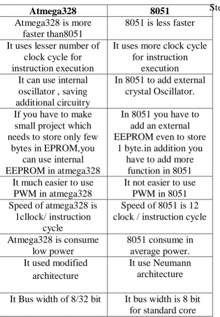
Table No:3.4Comparison between 8051 microcontroller and Atmega328:
Atmega328 8051
Atmega328 is more faster than8051
8051 is less faster
It uses lesser number of clock cycle for instruction execution
It uses more clock cycle for instruction
execution It can use internal
oscillator , saving additional circuitry
In 8051 to add external crystal Oscillator.
If you have to make small project which needs to store only few
bytes in EPROM,you can use internal EEPROM in atmega328
In 8051 you have to add an external EEPROM even to store
1 byte.in addition you have to add more
function in 8051 It much easier to use
PWM in atmega328
It not easier to use PWM in 8051 Speed of atmega328 is
1cllock/ instruction cycle
Speed of 8051 is 12 clock / instruction cycle
Atmega328 is consume low power
8051 consume in average power. It used modified
architecture
It use Neumann architecture
It Bus width of 8/32 bit It bus width is 8 bit for standard core
4. WORKING PRICIPLE
Capacitive power factor correction is applied to circuits which include induction motors as a means of reducing the inductive component of the current and thereby reduce the losses in the supply. There should be no effect on the operation of the motor itself. An induction motor draws current from the supply that is made up of resistive components and inductive components. The current due to the leakage reactance is dependent on the total current drawn by the motor, but the magnetizing current is independent of the load on the motor. The magnetizing current will typically be between 20% and 60% of the rated full load current of the motor. The magnetizing current is the current that establishes the flux in the iron and is very necessary if the motor is going to operate. The magnetizing current does not actually contribute to the actual work output of the motor. It is a catalyst that allows the motor to work properly. The magnetizing current and the leakage reactance can be considered as the passenger components of current that will not affect that the power drawn by the motor, but contribute to the power dissipated in the supply and distribution system.
Voltage & Current Measurement Unit-Current transformer (CT) is connected series with line, and Potential transformer (PT) is connected parallel with supply line. CT & PT are used to step down the voltage and current for resistor divider network.
Controller -The ATmega328 is a single-chip
microcontroller created by Atmel in the mega AVR family. The ATmega328 is commonly used in many projects and autonomous systems where a simple, low-powered, low-cost micro-controller is needed.
LCD-A microcontroller program must interact with the outside world using input and output devices that Communicate directly with a human being. One of the most common devices attached to a microcontroller is a Liquid crystal display. Some of the most common LCDs connected to the microcontroller are 16x2 and 20x2 displays.
Relay -Relay outputs are provided which operate to
connect or disconnect the capacitor banks depending upon of the power factor conditions.
Capacitor Bank-Capacitor bank is an assembly of
number of capacitors which are used to contribute KVA in the electrical system and finally improve the power factor. Shunt capacitors bank are arrangements of series/paralleled connected units.
Relay-A relay is an electrically operated switch.
Many relays use an electromagnet to operate a switching mechanism mechanically, but other operating principles are also used. Relays are used where it is necessary to control a circuit by a low-power signal or where several circuits must be controlled by one signal. Current flowing through the coil of the relay creates a magnetic field which attracts a lever and changes the switch contacts. The coil current can be on or off so relays have two switch positions and most have double throw switch.
Relay Driver Relay-Driver is interfaced with the
microcontroller output. It is used to drives the multiple relays as per the compensation required. Relay driver IC
5. SOFTWARE REQUIREMENT
Arduino sketch software.
6. CONCLUSION
In our project “Minimizing Penalty in Industrial Power Consumption by Engaging APFC Unit” in which the advanced method of the power factor correction by using Automatic power factor correction unit which has the many advantages over the various methods of the power factor correction. The switching of capacitors is done automatically by using the relay and thus the power factor correction is more accurate. Thus in this paper presented the possible advanced method for the correction of the power factor.
7. FUTURE SCOPE
There are several avenues for future research the application of complex valued? Neural network approach is implemented for contingency analysis using the offline data for training purpose. This method can be extended for online applications of realistic power system. For larger power system having thousands of variable input features selection for the neutral network plays an important role. As the size of the system increases the numbers of neutrons increases there by increases the training time. A method of mutual information between the input and output variables is to be investigated. In this research voltage constrained transfer capability is compared the future work implement the other constraints like thermal and economic considerations. A well-coordinated power system planning, control and operation is required for the future electric utilities as they will find themselves in an increasingly competitive environment. There is an urgent need for the development of methods, procedure and software tools to deal with various contingencies, wide range of operating conditions. This would help in further research on accurate transfer capability computations
REFERENCE
[1] SagarJundare, PranavUkkadgaonkar,
Minimizing Penalty in Industrial sector By Engaging Automatic power correction panel using microcontrolle.
[4] Power factor correction By John Ware
[5]Muhammad Ali Mazidi and Janice Gillespie Mazidi, “Microcontroller and Embedded Systems”.
[6] IEEE Transactions On Industrial Electronic Vol.
BIOGRAPHY
[1]R .B. PANDHARE is currently working as HOD & Professor in the dept. of
Electrical (E&P) Engineering Department.
[2]VITTHAL SHELKE
U.G studentEE(E&P) dept., PLITMS Buldhana, Maharashtra,
India.
[3]GANESH TANGADE U.G studentEE(E&P) dept., PLITMS Buldhana, Maharashtra,
India.
[4]ANIL PAWAR
U.G studentEE(E&P) dept., PLITMS Buldhana, Maharashtra,
India.
[5]ASHVINI KOTHALE U.G student EE(E&P) dept., PLITMS Buldhana, Maharashtra,India