---
- -
- - -
-
-
- - -
---- ----
- ---
.
---_
.
-
3745 Communication Controller
SY33-2054-6Maintenance Information Procedures (MIP)
Part 2
0
..
0CJ
..
0..
=
o
o
o
o
o
---.-
---
-
---
-
--
----
- .----
---
---,-
IBM 3745 Communication Controller
Models 210,310,410, and 610
IBM 3746 Expansion Unit
ModelsA11, A12, L13, L14, and L15
SY33-2054-6
Note!
Before using this information and the product it supports, be sure to read the general
information under" Notices" on page xiii.
Seventh Editlon (August 1991)
o
The information contained in this manual is subject to change from time to time. Any such changes will
i-\
be reported in subsequent revisions.
~/
Changes have been made throughout this edition, and this manual should be read in its entirety.
Order publications through your IBM representative or the IBM branch office serving your locality. Publications are not stocked at the addresses given below.
A form for reader's comments appears at the back of this publication. If the form has been removed, address your comments to:
International Business Machines Corporation Department 6R1 LG
180 Kost Road
Mechanicsburg PA 17055-0180
U.S.A.
or
IBM France
Centre d'Etudes et de Recherches Service 0762 BP 79
06610 La Gaude France
When you send information to IBM, you grant IBM a non-exclusive right to use or distribute the information in any way it believes appropriate without incurring any obligation to you.
©
Copyright International Business Machines Corporation 1988, 1991. All rights reserved.o
Contents
o
o
o
o
Maintenance Information Procedures, Part 1 of 2
Chapter 1. Introducing the IBM 3745 Communication Controller
Table of Contents for Chapter 1 Using this Manual
Special Tools . . . . Maintenance Philosophy
Using the 3745 Library for Service General Description .
Internal Organization Model Configurations Specifications and Features Configuration Identification . Control Panel Use . . . .
How to Perform Control Panel Operations
Chapter 2. START - How to Begin Troubleshooting
START - Console Use for Maintenance . . . . Problems During Machine, EC or MES Installation Symptom Index . . . . . . . . .
Using Reference Codes . . . . . Panel Codes . . . . Using the MIP FRU, Group Table FRU Machine Requirements Diagnostic Requirements . . . .
Chapter 3. MAPs for FRU Isolation of 3745 Failures
MOSS MAPs . . . . . . . . . Line Adapter MAPs
Channel Adapter MAPs Power MAPs
IOC bus MAP . . . .
Maintenance Information Procedures, Part 2 of 2
Chapter 4. How to Run the 3745 Diagnostics
Table of Contents for Chapter 4 Diagnostic Description . . . How to Run MOSS Diagnostics How to Loop MOSS Diagnostics How to Run the Panel Test . . . How to Run the Console Link Test How to Run the Power Control Bus Test How to Run Internal Function Tests
Messages for Manu'al Intervention During IOC Bus Diagnostics . . . How to Run the Wrap Test (WTT) for LlC 1, 3,4,5,6 or HPTSS Port How to Run the Wrap Test with IFTs for LlC 1, 3, 4, 5, 6 or HPTSS Port
~ C:::-,~'ght IBM Corp. 1988, 1991
How to Run the Channel Wrap Test Action 10 Take After a Diagnostic Run
Chapter 5. 3745 FRU Exchange
Exchange Precautions
FRU Physical Locations . . . . FRU Exchange Procedures " Repair Verification Procedure CE Leaving Procedure
Appendix A. Control Panel Code Definitions Appendix B. Maintenance Aids
PKD Maintenance Aids . . . . . Contacting Support . . . . Control Program Maintenance Aids MOSS Microcode Maintenance Aids Scanner Microcode Maintenance Aids Channel Microcode Maintenance Aids
List of Abbreviations Glossary . . . .
iv
IBM 3745 Communication Controller----~---". -- ---_.
-4-42 4-43
5-1 5-1 5-5 5-51 5-170 5-172
A-1
8-1 8-1
8-2
8-4
8-6
8-8
8-10
X-1 X-9
a
o
Figures
o
o
o
o
0-1.
3i45
(Basic Frame 01) Label and Power Rating Plate Locations xx 0-2. 3745 (Basic Frame 01) Label and Power Rating Plate Locations xx 0-3. 3746-A 11 (Frame 02) or 3746-A 12 (Frame 03) Label Locations xxi 0-4. 3746-L 13 (Frame 04) 3746-L 14 (Frame 05) 3746-L 15 (Frame 06)0-5. 1-1. 1-2. 1-3. 1-4. 1-5. 1-6. 1-7. 1-8. 1-9. 1-10. 1-11. 1-12. 1-13. 1-14. 1-15. 1-16. 1-17. 1-18. 1-19. 1-20. 1-21. 1-22. 1-23. 1-24. 1-25. 2-1. 2-2. 2-3. 2-4. 2-5. 2-6. 2-7. 2-8. 2-9. 2-10. 2-11. 2-12. 2-13. 2-14. 2-15. 2-16. 2-17. 2-18. 2-19.
Label Locations . . . .. . . . . . . Safety Labels . . . . Representation of Flow Through this Manual
3i45
Subsystems . . . . . . . . Control Subsystem (CSS) . . . . Transmission Subsystem if L1C Type 1 to 4.Transmission Subsystem if L1C Type 5-6 Low/medium Speed Transmission Subsystem if L1C Type 6 High Speed
High Performance Transmission Subsystem (HPTSS) Token-Ring Subsystem (TRSS) . . . . Maintenance and Operator Subsystem (MOSS) .. . Power Control Subsystem (PCSS) . . . . CCU Single Configuration . . . . CCU Twin Standby Configuration . . . . CCU Twin Backup or Dual Configuration . . . . Full Configuration of Adapter Buses . . . . DMA Bus Configuration . . . . 3745 Data Flow . . . .
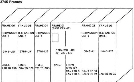
3745 Frame Locations . . . . CDF Channel Adapter Screen . . . . Channel Board Crossover Locations
CDF Line Adapter Screen
FESH Identification . . . . . . . . FESL Identification . . . . . . . . TSSB Board Layout . . . . TSST Board Layout . . . . . . . Panel Layout . . . . Maintenance Functions Menu . . . . Reference Code Screen . . . . TSS/HPTSS Diagnostic Selection Screen . . . . TRSS Diagnostic Selection Screen . . . . TSS/HPTSS Diagnostic Selection Screen . . . . TSS Service Screen . . . . Select/Release Screen . . . . Mode Control Screen . . . . L1C Type 1 and 4 Wrap Plug P/N65X8927 . . . . L1C Type 3 Wrap Cable P/N65X8928 . . . . L1C Type
5
and6
Wrap Plug P/N11F4815 . . . . L1C Types 1, 3 and 4 . . . . L1C Types 5 and 6 . . . . TSS/HPTSS Diagnostic Selection Screen . . . . TSS/HPTSS Diagnostic Selection Screen . . . . CDF Function Menu . . . . CDF Display/Update Function Menu . . . . CCU Operating Menu . . . . . . . . TSS Service Screen . . . . . . .xxi xxii 1-5 1-11 1-11 1-12 1-12 1-12 1-13 1-13 1-13 1-14 1-15 1-16 1-17 1-18 1-18 1-19 1-22 1-25 1-26· 1-28 1-30 1-30 1-31 1-32 1-35 2-2 2-12 2-47 2-53 2-63 2-71 2-71 2-72 2-72 2-72 2-73 2-73 2-74 2-77 2-80 2-84 2-84 2-85 2-90
-_
.. - - - _ . - . __ .- ---_._. __ . . . - -.---.---.-.. --~-... - -... ---.-.--.---~....
-... ---.---~---.-.---. ---.- ----.-_.-_._----2-20. Select/Release Screen . 2-21.
2-22. 2-23.
Mode Control Screen. . . . . . TSS/H PTSS Diagnostic Se.2:tion Screen TRSS Services Screen
2-24. Select Screen 2-25.
2-26. 2-27. 2-28. 2-29.
Connect/Disconnect Scree- . . . . TRSS Diagnostic Selectlo"': Screen TSS Service Screen
Select/Release Screen . . . . Mode Control Screen . . . . 2-30. TSS Service Screen
2-31. 2-32. 2-33. 2-34. 2-35. 2-36. 3-1. 3-2. 3-3. 3-4. 3-5. 3-6. 4-1. 4-2. 4-3. 4-4. 4-5. 4-6. 4-7. 4-8. 4-9. 4-10. 4-11. 4-12. 4-13. 4-14. 4-15. 4-16. 4-17. 4-18. 4-19. 4-20. 4-21. 4-22. 4-23. 4-24. 5-1. 5-2. 5-3. 5-4. 5-5. 5-6. 5-7.
Select/Release Screen . . .
Mode Control Screen . . . . TSS/H PTSS Diagnostic St:' ection Screen CDF Function Menu .. " .. .
CDF Menu . . . . CCU Operating Menu
MOSS Voltage Test Poin;s . . . PS Type 6 SW1 Actuator ' . . . . . . Console Outputs . . . . PSTY6 Test Points. . . . . . UEPO Switch . . . .
Primary Power Box . . . . MOSS Overview . . . . Power Control Bus layot:! . . . .
CCU Diagnostic Coverage . . . . IOC Diagnostic Coverage . . . . CA Diagnostic Coverage " . . . . TSS Diagnostic Coverage . . . .
TRSS Diagnostic Covera~e . . . . HPTSS Diagnostic Covera;e . . . . Console Outputs . . . . Cable Configurations . . . . Power terminator (Frame 01 Represented). . . . . . Power Control Bus Wrap C3rd . . . . Wrap Circuit of the Wrap Card . . . . Power Control Bus layot.:! . . . . Maintenance Functions Me:1U . . . . How to Select Diagnostics . . . . How to Enter an Option . . . .
Error Menu . . . . Diagnostic Messages Screen . . . . lIC Type 1 and 4 Wrap PI:Jg P/N65X8927 . . . . L1C Type 3 Wrap Cable P ~~55X8928 . . . . L1C Type 5 and 6 Wrap Pl..;g P/N11F4815 . . . . LlC Types 1,
3
and 4 . . . . LlC Types 5 and 6 . . . . . . . . 3745 Full Machine Config:;"ation . . . . . 3745-210, 310, 410 or 610 . . . .3746-011 . . . . . . . .
3746-012 . . . . . . . . 3746-013 . . . . 3746-014 . . . . 3746-015 . . . .
vi
IBM 3745 Communication Controllero
o
o
o
o
5-8. 5-9. 5-10. 5-11. 5-12. 5-13. 5-14. 5-15. 5-16. 5-17. 5-18. 5-19. 5-20. 5-21. 5-22. 5-23. 5-24. 5-25. 5-26. 5-27. 5-28. 5-29. 5-30. 5-31. 5-32. 5-33. 5-34. 5-35. 5-36. 5-37. 5-38. 5-39. 5-40. 5-41. 5-42. 5-43. 5-44. 5-45. 5-46. 5-47. 5-48. 5-49. 5-50. 5-51. 5-52. 5-53. 5-54. 5-55. 5-56. 5-57. 5-58. 5-59. 5-60. 5-61.3745 MOSS Board. Cards and Connectors . . . 5-13 3745 Storage, Control Boards and Cards for Models 210 and 410
3745 Storage, Control Boards and Cards for Models 310 and 610 3745 SACU Board and Connectors for Models 210 and 410 3745 SACU2 Board and Connectors for Models 310 and 610 3745 SACL Board and Connectors for Models 210 and 410 3745 SACL2 Board and Connectors for Models 310 and 610 3745 TCM Board and Connectors (Front) . . . . 3745 TCM Board and Connectors (Rear) . . . . 3745 TSSB Board and Cards . . . . 3745 TSSB Board and Connectors . . . .
3745 TSST Board Cards and Connectors . . . . 3745 LlC Unit Type 1 Board and Connectors . . . . 3745 L1C Unit type 2 Board and Connectors . . . . 3745 DMUX Packaging . . . . 3745 SMUXA/B Packaging . . . . LlC Unit Type 1 Packaging (for LlC Type 1-4) . . . . Line Numbers and Boards (for LlC Type 1-6) . . . . LlC Unit Type 2 Packaging (for LlC Type 5) . . . . LlC Unit Type 2 Packaging for LlC Type 6 Low-speed . . . . LlC Unit Type 2 Packaging for LlC Type 6 High-speed . . . . LlC Unit Type 1 Layout Board B2 (for LlC Type 1-4) . . . . LlC Unit Ty.pe 1 Layout Board B1 (for LlC Type 1-4) . . . . LlC Unit Type 2 Layout Board B2 (for LlC Type 5) . . . . LlC Unit Type 2 Layout Board B1 (for LlC Type 5) . . . . LlC Unit Type 2 Layout Board B2 (for L1C Type 6 Low-speed) LlC Unit Type 2 Layout Board B1 (for L1C Type 6 Low-speed) LlC Unit Type 2 Layout Board B2 (for LlC Type 6 High-speed) LlC Unit Type 2 Layout Board B1 (for LlC Type 6 High-speed) LlC Number I Line Address Tables for Frame 01 . . . . LlC Number I Line Address for Frame 04B/O . . . . LlC Number I Line Address for Frame 04E/G
LlC Number I Line Address for Frame 05B/O LlC Number I Line Address for Frame 05E/G
LlC Number I Line Address for Frame 06B/O
5-14 5-15 5-16 5-17 5-18 5-19 5-20 5-21 5-22 5-23 5-24 5-25 5-26 5-27 5-27 5-28 5-28 5-29 5-30 5-30 5-31 5-32 5-33 5-34 5-35 5-35 5-36 5-36 5-37 5-38 5-39 5-40 5-41 5-42 LlC Number I Line Address for Frame 06E/G . . . 5-43 3745 Channel Board Cards and Connectors . . . 5-44 3745 Channel Tail Gate and Standard Interface Test Points . . . . 5-45 3'745 Channel Tail Gate . . . 5-46 3745 Control Panel
3745 Primary Power Box Components . . . . Control Panel Removal . . . . PS Type 6 SW1 Actuator . . . . FOO Removal . . . . FOO Jumpering . . . . PS Type 2 . . . . HOD Removal . . . . HOD Jumpering (Old Model and New Models) . . . . Shipping Springs . . . . Shipping Springs . . . . CSP and FESL Cards . . . . FESH Card . . . . OMUX Card
SMUX AlB Switches
5-47 5-48 5-52 5-53 5-55 5-56 5-56 5-57 5-58 5-59 5-61 5-66 5-67 5-68 5-69
-,~~.~ ... -- ---~..:~~~--~ ... ~,
--.-.----~---5-62. SMUX A and SMUX B cards 5-70
5-63. LlC Cassette Type 1-4 5-71
0
5-64. LlC Cassette Type 5 and 6 5-72
5-65. Fan Assembly 5-73
5-66. TIC and TRM 5-75
5-67. Location of Jumper A and Switch Block B on the TIC Card 5-75
5-68. PTER Locations 5-77
5-69. Power Terminator (Frame 01 Represented) 5-77
5-70. Card Clamp Mechanism 5-78
5-71. Frame 01 Internal Access 5-80
5-72. AMD Filter Location 5-80
5-73. Filter Removal 5-81
5-74. Air Filter locations 5-81
5-75. Back Air Filter location 5-82
5-76. Power Services Screen 5-83
5-77. Acknowledge Screen 5-83
5-78. Frame 01 Internal Access 5-84 (~\
5-79. Air Moving Devices Location 5-84 l '_oj)
5-80. Air Moving Devices Removal 5-85
5-81. Air Moving Devices Location 5-86
5-82. Air Moving Devices Removal 5-87
5-83. Battery Location 5-88
5-84. Battery Removal 5-88
5-85. Power Services Screen 5-89
5-86. Acknowledge Screen 5-89
5-87. Frame 01 Internal Access 5-90
(~-)
5-88. Blower Assembly Removal 5-90
5-89. Frame 01 Internal Access 5-96
'---5-90. AMD Location 5-96
5-91. Air Moving Device Removal
· .
5-975-92. Heat Sink Removal 5-97
5-93. TCM Handle Attachment 5-97
5-94. TCM Retaining Screws 5-98
5-95. Actuation Tool, TCM Removal
·
.
5-985-96. Actuation Tool Usage 5-98
5-97. TeM Uncammed Position 5-99
r--"
5-98. TeM Removal 5-99
lJ'
5-99. TeM Protection
·
.
5-995-100. TeM Container
·
.
5-995-101. TeM Board
· .
5-1005-102. TCM Assembly
·
.
.
.
5-1005-103. TCM Inspection
·
.
5-1005-104. TeM Installation
· .
5-1005-105. Actuation Tool Installation 5-101
5-106. TCM Cammed Position 5-101
5-107. Actuation Tool Usage
·
.
5-1015-108. TCM Handle Removal
·
.
5-1025-109. Heat Sink Installation
·
.
5-1025-110. AMD Installation
· .
5-1025-111. PS Type 1 5-103
5-112. PS Type 1B
·
.
5-105I(-~
II
5-113. PS Type 2
·
.
5-1075-114. PS Type 3
·
.
5-108'-J
5-115. PS Type 4 5-109
ir
o
o
o
o
o
5-116. PSType5 5-111
5-113 5-114 5-117. PSType6
5-118. PS Type 7 5-119. 5-120. 5-121. 5-122. 5-123. 5-124. 5-125. 5-126. 5-127. 5-128. 5-129. 5-130. 5-131. 5-132. 5-133. 5-134. 5-135. 5-136. 5-137. 5-138. 5-139. 5-140. 5-141. 5-142. 5-143. 5-144. 5-145. 5-146. 5-147. 5-148. 5-149. 5-150. 5-151. 5-152. 5-153. 5-154. 5-155. 5-156. 5-157. 5-158. 5-159. 5-160. 5-161. 5-162. 5-163. 5-164. 5-165. 5-166. 5-167. 5-168. 5-169.
Phases . . . 5-116
Frame 01 Internal Access 5-116
PS Type 8 . . . 5-116
Fan Assembly . . . 5-118
Tail Gate Connector . . . 5-119
Primary Power Box in Frame 01 5-120
Channel Board, Tail Gate and Channel Power in Basic Frame 01 5-121 Channel Board, Tail Gate and Channel Power in Frame 02 5-121 Tail Gate . . . 5-122
Channel Board Power Supply 5-122
Channel Board and Power Enclosure 5-124
Board Assembly . . . 5-125
Primary Power Box in Frame 01 5-129
LAB1 and the Associated Power Supplies 5-130 LAB2, LAB3 and the Associated Power Supplies 5-130 LAB4 and Associated Power Supplies . . . 5-131 Line Adapter Power Supply . . . 5-131 Line Adapter Board, Cards and Crossovers (TSSB) 5-132 Line Adapter Board, Cards and Crossovers (TSST) 5-133
Enclosure for the Line Adapter Board 5-135
Back Plate Assembly . . . 5-136
Primary Power Box . . . 5-139 lIC Board Type 1 Assembly . . . 5-140
lIC Board Type 1 Enclosur~ Assembly 5-141
lIC Board Type 1 Assemblies 5-141
Primary Power Box . . . 5-143 lIC Board Type 2 Assembly . . . 5-144
lIC Board Type 2 Enclosure Assembly 5-146
lIC Board Type 2 Assemblies 5-146
Base Frame - Rear View 5-148
Primary Power Box in Frame 01 . . . 5-148
Cables and Cards of the MOSS 5-149
MOSS Board and Card Rail Assemblies Primary Power BOX in Frame 01 . . . . Frame 01 Front and Rear View . . . . Rear View of the SAC Gate Assembly Front View of the SAC Gate Assembly Card Clamp Mechanism . . . . SAC Air Moving Device Unit Location SAC Air Moving Device . . . . Primary Power BOX in Frame 01 .. Frame 01 Front and Rear View . . . . SAC Gate Assembly - Brackets . . . . . Card Clamp Mechanism . . . . Lower view of the SAC Gate Assembly Air Duct . . . . Upper View of the SAC Gate Assembly SAC Air Moving Devices Unit Location Air Moving Device Unit Removal TCM Board . . . . Board Screws
5-150 5-153 5-154 5-155 5-156 5-156 5-157 5-157 5-160 5-161 5-162 5-163 5-163 5-164 5-164 5-165 5-165 5-168 5-169
- ---~ -_ ... -~---.--" ----".-,~-~ ..
-.--~----o
o
Tables
o
o
o
0-1. 0-2. 0-3. 1-1. 2-1. 2-2. 2-3. 2-4. 2-5. 2-6. 2-7. 2-8. 2-9. 2-10. 2-11. 2-12. 2-13. 2-14. 2-15. 2-16. 2-17. 2-18. 2-19. 2-20. 2-21. 2-22. 2-23. 2·24. 2-25. 2-26. 4-1. 4-2. 5-1. 5-2. 5-3. 5-4.Part Numbers . . . . 3745 Power Supply CP/CB Reference Safety Label Numbers by Country Panel Display Values . . . . . General Symptoms .. . 3745 Console Symptoms Control Panel Symptoms Power Symptoms
Control Panel Code Table 3745 FRU Table . . . .
Requirements for CCU, Adapter or DMA buses. . . . . . Requirements for ITER/OTER. . . . . Requirements for MOSS. . . . . . Requirements for CADR. . . . . Requirements for CAl. . . . . . . . Requirements for CSP When Board Type Is TSST. . . . . . Requirements for CSP When Board Type Is TSSB . . . . Requirements for CSP When Board Type Is TSSB (con: "wed) .. Requirements for FESH When Board Type Is TSST . . . . Requirements for FESH When Board Type Is TSSB . . . . Requirements for FESL When Board Type Is TSST
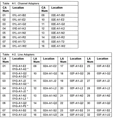
Requirements for FESL When Board Type Is TSSB . . . . Requirements for TIC. . . . . . Requirements for TRM. . . . . . Requirements for PS Type 4. . . . . . Requirements for PS Type 1 and 1 B. . . . . . Requirements for PS Type 2. . . . . . Requirements for PS Type 3. . . . . . Requirements for PS Type 5. . . . . . Requirements for PS Type 7. . . . . . Channel Adapters . . . . . . . . Line Adapters . . . . . . . . 3745 Power Supply Cross Reference . . . . Voltage Test Points . . . . . . . . Voltage Test Points . . . . Relation Between the CSP Card Location and the Power Services
xviii . xix xxiii 1-36 2-6 2-7 2-8 2-10 2-14 2-30 2-37 2-39 2-41 2-44 2-45 2-48 2-48 2-49 2-50 2-50 2-50 2-51 2-53 2-53 2-55 2-57 2-57 2-57 2-57 2-58 4-34 4-34 5-49 5-56 5-58
Screen . . . . . . .. 5-65
A-i. MOSS Control Panel Codes . . . A-1
o
---,--"---~--"
-o
/---''\
~---)
0
, , 1, ~
xii
IBM 3745 Communication Controller' J I hi k ! l' ' L
o
Notices
o
o
o
o
References in this publication to IBM products. programs, or services do not imply that IBM intends to make these available in all countries in which IBM operates. Any reference to an IBM product. program or service is not intended to state or imply that only IBM's product, program, or service may be used. Any functionally equivalent product. program. or service that does not infringe any of IBM's intellectual property rights may be used instead of the IBM product, program, or service. Evaluation and verification of operation in conjunction with other products, except those expressly designated by IBM, is the user's responsibility.
IBM may have patents or pending patent applications covering subject matter in this document. The furnishing of this document does not give you any license to these patents. You can send license enquiries, in writing, to the IBM Director of Commercial Relations, IBM Corporation, Purchase, NY 10577, U.S.A.
Electronic Emission Notices
Federal Communications Commission (FCC) Statement
Note: This equipment has been tested and found to comply with the limits for a Class A digital device, pursuant to Part 15 of the FCC Rules. These limits are designed to provide reasonable protection against harmful interference when the equipment is operated in a commercial environment. This equipment generates, uses and can radiate radio frequency energy and, if not installed and used in accordance with the instruction manual, may cause harmful interference to radio communications. Operation of this equipment in a residential area is likely to cause harmful interference, in which case the user .will be required to correct the interference at his own expense.
Properly shielded and grounded cables and connectors must be used in order to meet FCC emission limits. IBM is not responsible for any radio or television interference caused by using other than recommended cables and connectors or by unauthorized changes or modifications to this equipment. Unauthorized changes or modifications could void the user's authority to operate the equipment.
This device complies with Part 15 of the FCC Rules. Operation is subject to the following two conditions: (1) this device may not cause harmful Interference, and (2) this device must accept any interference received, including
interference that may cause undesired operation.
For Canada, Canadian Department of Communication Statement, GX27-3883, applies.
Trademarks and Service Marks
The following terms. denoted by an asterisk (*), used in this publication. are trademarks or service marks of IBM Corporation in the United States or other countries:
AS/400
Personal System/2
IBM Quietwriter
PC/XT
Selectric
The following terms. denoted by a double asterisk ( .... ). used in this publication. are trademarks of other companies:
Mylar Scotch Monotype
POSTSCRIPT
xiv
IBM 3745 Communication ControllerE.
I. du Pont de Nemours & Co .. Inc.Minnesota Manufacturing & Mining Company The Monotype Corporation, Limited
Adobe System Incorporation
o
~)
Safety
o
Product Safety Information
General Safety
This product meets IBM safety standards.
For more information, see the: IBM Telecommunication Products Safety Handbook, GA33-0126.
o
o
o
o
Safety Notices
CAUTION - - - ,
Hazardous voltages are still present in some areas of the 3745 when power is OFF
ATTENTION - - - ,
Presence de tensions dangereuses dans certaines parties du 3745 meme lorsque I'unite est hors tension
PRECAUCION - - - ,
Con la corriente apagada todavia hay voltages peligrosos en algunas areas del 3745
r; Copynght IBM Corp. 1988, 1991
VORSICHT - - - ,
Gefahrliche Spannungen auch bei ausgeschaltetem Gerat vorhanden
ATTENZIONE - - - ,
Tensioni pericolose sono ancora presente anche se I'unita 3745 e spenta
CUIDADO ---~
Voltagen ainda presente em algumas areas da 3745 mesmo quando desligada
Safety
Service Inspection Procedures
Introduction
The following procedures help the service personnel check whether the 3745 conforms to IBM safety criteria. They are to be used each time the 3745 safety is suspected.
The 3745 areas and functions checked through these procedures are:
1. External covers 2. Safety labels
3. Safety covers and shields 4. Grounding
5. Circuit breaker and protector rating 6. Input power voltage
7. Power On indicator On
8. Emergency power OFF.
Important Notes:
• The 3746(s) are powered On and Off through the basic frame 3745.
Hazardous voltages are still present in some areas of the 3745 when power is Off.
• Steps 1 through 6 must be performed with the power OFF; that is, on the 3745 and 3746{s):
CB1 tripped (switched off) on the 3745,
and
xvi
IBM 3745 Communication ControllerCustomer's power supply switch OFF. do not remove the power cord in order to maintain the ground protection. 1. External covers
Check that:
• They are all present on the 3745 and 3746(s).
• They are locked with two kind of locks: flat blade screw for IBM access area and hex head for customer access area (refer to the 3745 Parts Catalog). • They can be fully opened.
• Appropriate service clearances and accesses are provided around the frames with external covers opened. Leave all external covers opened to allow further safety inspection steps.
2. Safety labels Check that:
• All the safety labels are at the places indicated by letters in "Safety Label Locations" on page xx.
• Each label is of the model corresponding to the letter as shown on "Safety Label Identifications" on page xxii.
3. Safety covers and shields
Referring to FRU location (Chapter 5) check that:
• All the safety covers are present and secured with screws.
• All the voltage terminal boards (T8s) are protected by a plastic shield screwed on top of the T8.
],
o
o
o
o
o
4. Grounding
Refer to "Volume 4, page YZ110 10 YZ114" for grounding jumper locations
Check that:
• Electrical continuity is assured, within each frame, between the frame ground and the terminals indicated on the ground distribution diagrams.
• Electrical continuity is assured between the 3745 and 3746(s), frame grounds and to the premises grounding system, through the 3745 power cord.
5. Circuit breaker and protector rating
Refer to Table 0-2 on page xix for CB and CP locations.
Check that:
• All CBs and CPs in the 3745 are rated at the indicated value in Table 0-2 on page xix. If the rating is not indicated, check the part number against the 3745
Parts Catalog, 5135-2010.
6. Input power voltage
The power rating plate indicates the voltage ranges available (200/220/240 or
346/380/415) .
The voltage label (label E) indicates the input voltage for which the 3745 is wired.
Performing a Power Conversion Inspection.
• A power conversion inspection must be performed on any 3745 Communication Controller that has been converted from 50 Hz to 60 Hz, from 60 Hz to 50 Hz, from 220 V to 380 V, or from 380 V to '220 V.
• The following procedure is on Iy used for frame 01 (base frame) which contains the Primary Power Box (PPB). Each
component must be inspected as described.
Refer to Figure 5-2 on page 5-6 to locate the frame 01 and the PPB.
• Inspection
Check against the Table 0-1 on page xviii for the correct primary power part numbers for the specified 50 Hz or 60 Hz use.
'MlI' , d' ,,'WI Y"N' H N It'rld"'k\ WU H II " ! " ! l i l t ! HI! I t . . .
Safety
-Check for the correct PS type 8 : P/N5495884 for 50 Hz or
P/N6495898 for 50 Hz
In case of discrepancy. contact your support structure.
Refer to Figure 0-1 on page xx for power rating plate location and voltage label and:
• "Volume 4. page YZ561 to YZ564" for the primary power box voltage adjustment,
• "Volume 4, page YZ576" for the power box PS Type 6 voltage adjustment and
• "Volume 4, page YZ578" for the power supply PS Type 8 voltage adjustment.
Check that:
• The power rating plate is consistent with the voltage level measured at the customer's power supply. If not, inform your branch office.
Important Note:
Since the 3745 can be remotely powered On, all the following procedures must be
performed with the Power Control function on the 3745 control panel set to Local mode.
7. Emergency power
OFF
Ask the customer to connect the power cord to the customer's mains supply, put CB1 On, and power ON the 3745 (Power Control function to Local on the control panel).
Then operate the EMERGENCY switch to POWER OFF ('0') and check that:
• The 3745 is powered Off.
• The diskette and disk drives are stopped.
• All the fans are stopped, except MOSS.
• The convenience outlets on the 3745 are not supplied with ac power.
Relatch the EMERGENCY switch, then power ON the controller.
8. Power ON Indicator
Once the controller is powered On, check that the Power On indicator On on the 3745 control panel is lit. The indicator is located to the right of the Power ON/Reset key, refer to Figure 1-25 on page 1-35.
Safety
r--Table 0-1. Part Numbers
r
-Primary Power Assembly
PiN 6495105
US and Canada
208.220,240V
60 Hz
PIN 6495106
JAPAN
200.220
50 Hz
PIN 65X8688
JAPAN
200.208,240
60 Hz
PIN 6495107
All
countries200,220
50 Hz
PIN 65X8689
All
countries200,208,220,240
60 Hz
PIN 6495688
All
countries380,400,415
50 Hz
PIN 65X8690
All
countries380
60 Hz
xviii
IBM 3745 Communication ControllerPower Cord
PIN 6495844
PIN 6495845
P.'N 6495845
PiN 6495845
PIN 6495845
PIN 6495846
PiN 6495846
Convenience outlet Voltage
117V
PIN 357995
100V
PIN 357995
100V
PIN 357995
200V
PIN 418835
220V
PIN 418835
220V
PIN 418835
220V
PIN 418835
o
'.
Safety
o
3745 Power
Supply
CP/CS Reference
Table 0-2. 37!: =ower Supply CP/CS Reference
Frame CB/CP Location Rating PS
Frame 1 :81 01E 40A/220V C81 01E 2SA/380V
CP1 01E 3A PSTY8 CP1 01F 1.SA PSTYB SP2 01F 1.SA PSTYB CP3 01F 1.SA PSTYB CP3 01E 6A PSTY1-A CP4 01E 3A PSTYS/7 CPS 01E 3A PSTY3
o
CP6 01E 3A PSTY2 CP7 01E 6A PSTY4 CP8 01E BA PSTY1-B CP9 01E 3A Outlet Frame 2 CP1 02J-AO 6A PSTY4 CP2 02J-AO 3A PSTY3 CP3 02J-AO 6A PSTY4 Frame 3 CP 03J-AO BA PSTY4o
Frame 4 CP1 04A-AD 6A PSTYS/7CP2 04A-AD BA PSTYS/7
Frame S CP1 OSA-AD BA PSTYS/7 CP2 OSA-AD BA PSTYS/7 Frame 6 CP1 OBA-AD BA PSTY7
CP2 OBA-AD 6A PSTY7
o
o
Safety
Safety Label Locations
On the following figures, labe s are designated by letters. A particular wording corresponds to each letter (see "Safety Label Iden::~:ations" on page xxii).
Figure 0-1. 3745 (Basic Frame Ot) Label and Power Rating Plate Locations
DETAIL A
ER I AI.. ~ER (STAMPED)
ATIONAL STANDARD PLATE
Figure 0-2. 3745 (Basic Frame Ot) Label and Power Rating Plate Locations. (Detail).
XX IBM 3745 Communication Controller
o
(--)
\. ,
o
o
o
o
o
j l t! I
Safety
Figure 0-3. 3746-A11 (Frame 02) or 3746·A12 (Frame 03) Label Locations
Figure 0-4 (Part 1 of 2). 3746-L13 (Frame 04) 3746-L14 (Frame 05) 3746-L15 (Frame 06) Label Locations
Figure 0-4 (Part 2 of 2). 3746-L13 (Frame 04) 3746-L14 (Frame 05) 3746-L15 (Frame 06) Label Locations
---
-Safety
Safety Label Identifications
The safety labels shown in Figure 0-5 are in English. They are also available .:- other languages. See ··Safety Label Part Numbers by Country" on page xxiii for ordering.
LABEL A
HAZARDOUS AREA TRAINED SERVICE PERSONNEL ONLY
LABEL B
LINE VOLTAGE PRESENT WITH MACHINE POWER
OFF
LABEL C
TURN MAIN LINE SWITCH
"0FP' BEFORE REMOVING
LABEL E
THIS MACHINE IS WIRED FOR V
See logic drawings for alternate voltage insn
LABEL D
LABEL G
This equipment has been
tes:e:
with a class a computing device and hes bee" found to comply with pert 15 FFC rules. See ir.s:ruction manual. Operation in a residential are: may cause unacceptable interference to r:dio and tvreception requiring the operc::r to take whatever steps are necessary to corre:: the interference
LABEL H
WARNING
High grounding conductor currer:. Grounding circuit continuity is vital for safe o::eration of machine. Never operate machire with grounding
conductor disconnected
TILT LABEL
CAUTION
US:: CARE WHEN MOVINGO~ ~OUGH SURFACES. DO 'OT TIP MORE THAN 10 J=:GREES.
DO ~OT REMOVE THIS LABEL
LABEL R
UK WARNING
CAUTION
REMOVE PRIMARY POWER BEFORE REMOVING COVER
CAUTION
WA=<''JING
CONNECT ONLY A?PARATUS COMPLYING WITH BS 6301 TO THESE PORTS
LABEL X
DUE TO CONNECTED EQUIPMENT HAZARDOUS VOLTAGES
TO DISCONNECT THIS
t..;'-iT COMPLETELY,
C31 ON MAIN FRAME
M..;STBE IN
MAY BE PRESENT AT ANY TIME T.-E
OFF
POSITIONFigure 0-5. Safety Labels
xxii
IBM 3745 Communication Controllero
i
, W',,"!+4=; d+h =* I
o
o
o
o
o
Safety Label Part Numbers by Country
The following table gives the label group part
number for each frame according to the
language(s) of the country in which the 3745 is
installed.
Table 0-3. Safety Label Numbers by Country
LANGUAGE FRAME FRAME 02
or
01 03 PART PART NUMBER NUMBER
Danish
03F4314
03F4334
Dutch
03F4316
03F4336
English
03F4302
03F4322
*
03F7770
03F7770
Finnish
03F4305
03F4325
French
03F4304
03F4324
French/Dutch
03F4306
03F4326
French/German/Italian 03F4315
03F4335
Canadian French
03F4303
03F4323
German
03F4307
03F4327
Italian
03F4308
03F4328
Japanese
03F4313
03F4333
Norwegian
03F4309
03F4329
Portuguese
03F4310
03F4330
Spanish
03F4311
03F4331
Swedish
03F4312
03F4332
*UKONLY
FRAME 04
or
TILT LABELOS
PART PART NUMBER NUMBER03F4349
03F4462
03F4351
. 03F4464
03F4337
03F4417
03F7770
03F4340
03F4453
03F4339
03F4452
03F4341
03F4454
03F4350
03F4463
03F4338
03F4451
II
03F4342
03F4455
I03F4343
03F4456
I03F4348
03F4461
, II
03F4344
03F4457
I
,
03F4345
03F4458
!
I03F4346
03F4459
I
03F4347
03F4460
I
o
II
xxiv
IBM 3745 Communication ControllerI
o
About This
Book
o
o
o
o
Aim of this book
The MIP is a guide fa" ::ult isolation and repair of the 3745 Communication Controller. It is expected that the customer has _sed the Problem Determination Guide, SA33-0096 prior to calling IBM for service and the MIP 0:':$ not duplicate the tasks specified by the Problem Determination Guide.
The MIP gives the se:-\ :e representative the information needed to:
• Analyze problems :; symptoms reported by the system user.
• Restore normal 3-!.: operation.
Who should read this :.;.ok
The person using this - anual should be:
• Trained to service :-e 3745 and 3745 Expansion frames.
• Familiar with the :::-:figuration of the system to which the 3745 is connected.
• Familiar with the :::,~ration of the 3745, as described in IBM 3745 Communication Controller Maintenance Infor,-:tion Reference, SY33-2056 and IBM 3745 Communication Controller Service Functions, SY33-2:::3. which are part of this Maintenance Library.
The intended audiencE =or this manual are Product-Trained Customer Engineers (PT CE). The Product Support-Trained Custo-er Engineer (PST CE) is also expected to refer 10 the manual when he is required to perform tf'.; same tasks as the PT CEo
How this book is organ2.ed
This manual is organi::d as follows:
• Safety information '3 at the start of the manual followed by information about the maintenance library and relatec :ocuments.
• Chapter 1 gives a ;~neral description of the product and its features and also a description of the maintenance philcs:phy.
• From Chapter 2 t:-.""Jugh Chapter 5, this manual is designed so that the information is presented to the user in the sar~ order as he will require it for most service calls. The user is told where to go next for each path :~rough this part of the manual.
• At the back of the -3nual are Appendix A and B, abbreviation list and glossary. This information is for reference purp~es.
()
()
o
Summary of
Changes
This revised edition takes ,~~o account the new 3745 models: 310 and 610.
Also corrections and impr:-;ements relating to the previous edition have been inserted.
o
o
o
o
- - --- . ---- - - - -._.
__
. . ----.-. _.-_.-.o
\ '- -/
. /
o
, \ 6 ...I.
o
3745 BIBLIOGRAPHY
Service Personnel Definitions
o
o
o
o
Definition
Product trained CE (PT CE): hardware CE also able to fix problems in the microcode Also called:
CE1
1st Level CE CE Phase 1
Product support trained CE (PST CE): hardware CE also able to determine and fix problems in the microcode Also called:
CE2
2nd Level CE CE Phase 2 Specialist Support
Hardware Central Service (HCS) May include:
Dispatchers PT CEs PST CEs
Program service representative (PSR) Also called:
Program support CE Software CE
~ Copyright I BM Corp. 1988, 1991
Uses
RETAIN console 3745 control panel 3745 console MIP
Service Functiqns Installation Guide Parts Catalog
Basic Operations Guide Problem Determination Guide Connection and Integration Advanced Operations Guide Wiring Diagrams (YZ Pages) Same as PT CE, plus: MIR
Diagnostic Descriptions Principles of Operation All 3745 tools and books
Operating systems, access methods, and NCP/EP library
' _ _ MeN M M ... UN' • * ulr"IW" nI" r
Customer Information
SuppEed with the 3745
(Witho_~ :Jinder)
Man~
Title Telecommunication Products Safety Handbook
Purp~e: Recalls elementary safety principles that must be observed when installing and connecting telecommunication products on a customer site.
Audl:-::::e: (1) Customers (2) IBM CEo
Volum= A
(With:; -der SX11-8300)
Manwi
Title- 3745 Master Index
Purp:::e: Helps the user find information in the 3745 customer documentation.
Aud!::-ce: (1) Telecommunication network specialist. (2) Network operator, System operator.
Title- 3745 Connection and Integration Guide
Purp~e: Explains how to install, replace, and remove the L1Cs, and how to plug and unplug cables for all attachments. Also explains how to integrate the 3745 into a telecommunication network.
Audi::-ce: (1) Telecommunication network specialist. (2) Network operator, IBM product trained CEo
Title: 3745 Console Setup Guide
Purp:::e: Explains how to install 3745 consoles.
Audi::-ce: (1) Telecommunication network specialist. (2) Network operator, IBM product trained CEo
Voluma B
(With b)-der SX11-8301)
Mantai
Title: 3745 Advanced Operations Guide
Purp~e: Describes all maintenance and operator subsystem functions.
Audi~-ce: (1) Telecommunication network specialist, system programmer. (2) IBM product trained CEo
xxx
~:M 3745 Communication Controller()
Order Number
GA33-0126
Order Number
SA33-0172
SA33-0129
SA33-0158
Order Number
Volume C
o
(With binder SXI'-830')o
o
o
o
Manual
Title: 3745 Basic Operations Guide
Purpose: Provides the basic procedures needed for the da .' operation of the 3745.
Audience: (1) Operator. (2) Network operator, installation cjydinator, IBM product trained CEo
Title: 3745 Problem Determination Guide
Purpose: Provides problem determination procedures.
Audience: (1) Network operator, system operator. (2) IBM ;:--:juct trained CEo
Other Customer Information
Manual
Title: 3745 Introduction
Purpose: Provides introductory information. Describes highlights of the 3745.
Audience: (1) DP management, IBM marketing. (2) Operato~ 13M system engineer and service personnel.
Title: 3745 Configuration Program
Purpose: Can be run from an IBM PC, PC convertible, or a~ i equipment of the IBM Personal System/2 to configurate the 37!.:.
Audience: (1) Network DP Manager, IBM marketing represer:ative and system engineer. (2) Other customer users.
Title: 3745 Preparing for Connection
Purpose: Provides plugging sheets and information to prepa~e the 3745 cable installation. Explains how to fill in the
LIes:
configuration sheets.Audience: (1) DP manager, facilities technician, IBM Marketi~~. (2) IBM system engineer and service personnel.
Title: System/360, System 370, 4300 Processors InpuUO_~;:)Ut Equipment IM-PP
Purpose: Gives reference information to plan the physical i:-stallation of the 3745.
Audience: (1) DP manager, facilities technician, IBM Marketi~~. (2) IBM system engineer and service personnel.
Title: 3745 Principles of Operation
Purpose: Gives an understanding of the 3745 instruction
an:
command set. Audience: (1) System programmer, IBM system engineeran:
programservice representative. (2) System analyst, IBM r.arketing representative and service personnel.
" '
Order Number
SA33-0098
SA33-0096
Order Number
GA33-0092
GA33-0093
GA33-0127
GC22-7064
SA33-0102
... - - - -... -~----.--- --~--" -.. ,-~."~ .-.---~-.. ----"-~.--"-- ""
Service Information
Supplied with the 3745
Volumes 1-1 and 1-2
(With :~":J binders SX11-8300)Manual
Title. 3745 Service Master Index (SMI)
Purp~e: Help the user find information in the 3745 models 210 and 410 shipping group documentation.
AUG :'":ce: (1) IBM product trained CEo (2) IBM product support trained CEo Title: 3745 Maintenance Information Procedures (MIP)
Pur;cse: From exits from the Problem Determination Guide, or from error information given by the machine. provides procedures for isolating and fixing the 3745 failures.
Aut:: :~ce: (1) IBM product trained CEo (2) IBM product support trained CEo
Volume
2
(Witho_~ binder)
Manual
Title: 3745 Service Functions
Pur;>...-se: Describes how the MOSS service functions are used from the 3745 console.
Audie-ce: (1) IBM product trained CE. (2) IBM product support trained CE.
Volume 3
(With b~~der SX11-8301)
Manual
Title: 3745 Installation Guide
Purp8'5e: Provides instructions to install or relocate the 3745.
Audie.,ce: IBM product trained CEo
Title: 3745 Parts Catalog
Pur~e: Provides reference information for ordering 3745 parts, assemblies,
and subassemblies.
A(jdie:-ce: (1) IBM product trained CE. (2) IBM part distribution centers. Title: 3745 Wiring Diagram (YZ Pages)
Pur;>:se: Provides detailed schematic information on power wiring, board to board interconnections, locations, card population, jumpering, and interfaces.
Aud:~~ce: (1) IBM product trained CEo (2) IBM product support trained CE and Product Engineering.
xxxii
iBM 3745 Communication ControllerOrder Number
SY33-2080
SY33-2054
Order Number
SY33-2055
Order Number
SY33-2057
S135·2010
Part Numbers (See Note)
o
\ ~
o
o
o
o
o
I I hid...' + L.
Manual Order Number Title: 3745 External Cable Reference SY33-2075 Purpose: Describes interface cables and wrap plugs used for conre:ting the
3745 to the console(s) and lines.
Audience: (1) IBM product support trained CEo (2) IBM Product En~,:-eering.
Note: Manufacturing documents, cannot be ordered from the IBM dis:~ :)Ution centers.
Volume 4
(Without binder) Manual
Title: 3745 Diagnostic Descriptions
. Purpose: Describes the diagnostic programs and the purpose of e~::,
routine.
Audience: (1) IBM product support trained CEo (2) IBM Product Eng ~~ering.
Volumes 5-1 and 5-2
(Without binder) Manual
Title: 3745 Maintenance Information Reference (MIR)
Purpose: Provides reference information to locate failures in the
3:-.!5
in complement to the Maintenance Information Procedures.Audience: (1) IBM product support trained CE. (2) IBM Product Eng:~eering.
Other Service Information
Manual
Title: 3745 Channel Adapter On-Line Tests
Purpose: Describes the 3745 channel adapter OL Ts and how to run :hem. Audience: (1) IBM product trained CEo (2) IBM product support trai:-€-:1 CE. Notes:
Order Number SY33-2059 Order Number SY33-2056 Order Number D99-3745A (See Note 1)
1. Shipped from Poughkeepsie with the S/370 channel adapter OL T ta~e. Cannot be ordered from the IBM distribution centers.
" ---"--- --- ---"---~ --" ' " - - - -
~-~-Related
Signal Converter Products Information
()
The following publications relate to IBM signal converter products and are cu .... ently available:• 7861 Description and Planning Guide, GA33-0122.
• 7861 Setup, User's Guide, and Problem Analysis, SA33-0123. • 7861 Maintenance Information and Parts Catalog, SY33-2062. • 7868 Guide to Operation. GA33-0134.
• 5822-10 Guide to Operation, GA33-0118.
• 5822-18 Guide to Operation, GA33-0136. • 5858 Guide to Operation, GH11-3027.
• 5858 Maintenance Information and Parts Catalog. SY12-8246.
• Link Problem Determination Aid, SY33-2064.
• Power Supply and Telecommunication Connections, GA33-00S4.
f~
11\,--~
o
o
o
o
o
Related NCP Service Information
NCP and EP Reference Summary and Data Areas (L Y30-:
·96
for V4R3.1 only)NCP and EP Referenqe Summary and Data Areas (L Y30-5:.J3 for V5 only)
These manuals are for system programmers and IBM p ... :-;tram service representatives. They provide quick access to often-used diagnostic and debugging inf:;-·mation about NCP and EP in PEP
environment.
NCP, SSP, and EP Diagnosis Guide (L Y30-5591)
This manual is designed to help customers and IBM pro;::--am service representative isolate and define problem in NCP Version 3, NCP Version 4, NCP V4 SUbs::. NCP Version 5, and EP in the PEP
environment using SSP Version 3. The primary purposE :>f the manual is to help the user interact with the IBM Support Center to resolve a problem. Procedures in these manuals describe how to:
• Determine whether the problem is in NCP
• Use relevant information to describe the problem
• Gather appropriate documentation about the proble:-:-:
• Report the problem to the IBM Support Center
In addition, it includes detailed descriptions of how to use the programming tools available with NCP and SSP.
NCP and EP Reference (LY30-5569 for V4R3.1 only)
NCP and EP Reference (LY30-5605 for V5 only)
These manuals contain reference material describing the internal organization and function qf the NCP and the EP in PEP environment. These manuals provide information for customization and diagnosis.
. _ - -
---,---,-~---,,~-.-~---~-~---~-, ----,,~~-~~,-o
(~ "\
,J
( ) i'
o
o
o
o
o
Chapter 4. How to Run the 3745 Diagnostics
Table of Contents for Chapter 4
Diagnostic Description
3745 Diagnostics . . . . Errors During Diagnostics .. . Diagnostics Monitoring
Checkout Diagnostics . MOSS Diagnostics
Power Subsystem Tests . . . Functional Area Diagnostics Diagnostic Identification '" CCU Diagnostics
IOC Diagnostics . CA Diagnostics TSS Diagnostics TRSS diagnostics HPTSS Diagnostics CA Online Test (OL T) Network Power OFF Test LlC Wrap Test . . . . How to Run MOSS Diagnostics How to Loop MOSS Diagnostics How to Run the Panel Test . , . How to Run the Console Link Test
Local/Remote or Alternate/RSF Link Tests How to Run the Power Control Bus Test
Power Control Bus Test Procedures PCB Wrap Card Description . . . . Types of Failure Detected . . . .
How to Run Internal Function Tests . . . . Messages for Manual Intervention During IOC Bus Diagnostics How to Run the Wrap Test (WTT) for LlC 1, 3, 4, 5, 6 or HPTSS Port How to Run the Wrap Test with IFTs for LlC 1, 3, 4, 5, 6 or HPTSS Port How to Run the Channel Wrap Test
Action to Take After a Diagnostic Run Diagnostic Result Analysis . . . .
© Copynght IBM Corp. 1988, 1991
1+ !t\'ItJHzib'H# I**dril'
.!
Diagnostics
4-2 4-2 4-2 4-2 4-3 4-4
4-6
4-7 4-7
4-8 4-9
4-10 4-12 4-14
4-15 4-16
4-17
4-18 4-19
4-20 4-21 4-22 4-22 4-24 4-24
4-26 4-28 4-29
4-33 4-35 4-37 4-42 4-43 4-43
~~-.-.-.---.. -- _.
-Diagnostics
Diagnostic Description
3745 Diagnostics
A full and detailed description of diagnostics is given in "3745 Service Functions" and
"Diagnostic Description".
Two groups of diagnostics run on the 3745:
1.
Automatic:IMLlIPL checkout diagnostics including MOSS diagnostics.
2. Controlled:
a. Power subsystem tests b. Functional area diagnostics
• Internal Function Tests (IFTs) • Wrap tests
• OLTs.
Diagnostics are run during the installation procedure and when a fault is detected to isolate a field-replaceable unit that caused the failure. They are also executed after
a
repair is performed, to check that the hardware area is working correctly. They have to be run before and after an EC or MES has been installed in the area concerned.Diagnostics may be run in offline mode when the 3745 is fully available or in concurrent mode. In
4-2
IBM 3745 Communication Controllerconcurrent mode, the diagnostic must be selected in the specific area and will run only in configured units. These units must be available at that time.
Errors During Diagnostics
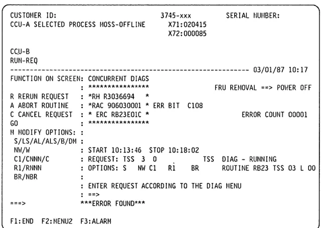
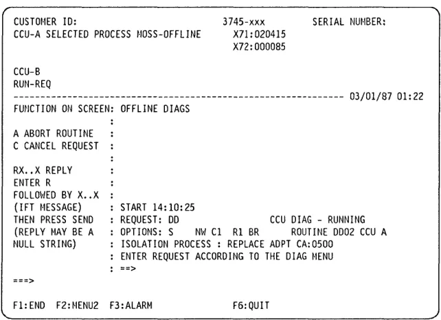
When the MOSS diagnostic program detects a failure, a three-digit code is displayed on the control panel.
When the internal function tests detect an error, a reference code is posted on the 3745 console.
Diagnostics Monitoring
The functional diagnostics are monitored by the Diagnostic Control Monitor (DCM) and the Command Processor (CP).
The diagnostic control monitor is loaded when the diagnostic utility program is selected from the 3745 function menu.
It automatically restricts diagnostic testing to the elements defined in the Configuration Data File (CDF), powered ON and disconnected from the NCP.
(~)
I1:1
o
o
o
o
o
Checkout Diagnostics
The checkout diagnostics are designed to test the hardware of the CCU, switch, laC, channel adapter, CSP part of the line adapter, TIC and the PLC card.
For the CA, LA, and TRA, they are part of the
~icrocode and located in the ROS of the adapter Itself. They run automatically every time the power is applied to the respective adapter, that IS, at power ON time before IML, or when respective power is started, (power ON reset line).
The PLC checkouts only run when power is applied to the power subsystem and are successful when the power control and service mode indicators are displayed.
Diagnostics
For the CCU, switch and laC, the diagnostics are located on the disk and run during IPL.
For the CA, TSS, and HPTSS they are also automatically run when the internal function tests are started.
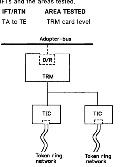
For the TIC, the Token-Ring wrap test is automatically run at each TIC Open command from the NCP. This TIC Internal Lobe Media tests the ring up to the local wiring concentrator (IBM 8228), or up to the point where it is
unplugged before the 8228.
If an error is detected, the MOSS analyzes the problem and presents a control panel code or a reference code.
Diagnostics
MOSS Diagnostics
CCUA
BUS
SWITCH CHANNEL ADAPTERS
CCUB
MAC
UC
BUS
POWER SUB SYSTEM
POWER BUS
DFA
CONSOLE SWITCH (RPQ)
FDD
HDD
CONTROL PANEL
I-~I~
---""""'11
LOCL..--_---ol---L _
J
..
CONSOLEr
-I
OR
ALT CONSOLE
1----~I--}l1
OC£r1
DeE.~
L..--_---o
l __I .
I IREM CONSOLE
Figure 4-1. MOSS Overview
The MOSS diagnostics can be run in concurrent mode.
1. Basic MOSS tests
They are designed to test the following units: • M PC (Moss Processor Card)
• MSC (Moss Storage Card) • MAC/MAC2 (Moss Adapter Card) • MCA (Moss Console Adapter Card) • DFA (Disk File Adapter Card) • HDD (Hard Disk Drive) • FDD (Flexible Disk Drive).
The basic MOSS tests are run whenever the following functions occur:
4-4
IBM 3745 Communication Controller• Power ON reset • Moss IML • General IPL.
~---...
RSF CONSOLE
Partial MOSS diagnostics also run for re-IML and for certain other MOSS functions. For example: MOSS dump.
IF A CRITICAL FAILURE IS DETECTED DURING ANY OF THE MOSS DIAGNOSTICS, A CODE WILL BE DISPLAYED ON THE CONTROL PANEL.
Refer to "How to Run MOSS Diagnostics" on page 4-19 for execution.
2. loop on MOSS diagnostics
Refer to "How to Loop MOSS Diagnostics" on page 4-20 for execution.
o
./-\
\" )
o
o
o
o
o
Basic tests will loop until an error is detected or an exit from this option is performed.
Diagnostics
3. Local/Remote/RSF console link tests
Refer to "How to Run the Console Link Test" on page 4-22 for execution.
They are individually selected tests which will test the hardware connecting the respective consoles.
Diagnostics
Power Subsystem Tests
1.
Control panel testThis test is designed to ensure that all the keys and displays are working correctly. The control panel bus and the PLC (Power
Logic Card) are also partially tested.
This diagnostic can be run in concurrent mode; refer to "How to Run the Panel Test" on page 4-21 for execution.
CONTROL PANEL
TO
PO'tfER
SUPPLIES
PAC
PLC
P 0
w
E R
B
U
S
~
BASE FRAME
Figure 4-2. Power Control Bus Layout
4-6
IBM 3745 Communication ControllerP 0
w
E R
B
U S
2
...
2.
Power control bus testThe power control bus test function allows the CE to check the interface between the
PLC card and the different power supplies of the 3745.
This function is dedicated to CE use only.
When the power control subsystem loses the control of a power supply due to an interface problem, a BER is logged by the MOSS. Based on this information, the CE may have to check the power control bus.
This diagnostic can be run in concurrent mode; refer to "How to Run the Power Control Bus Test" on page 4-24 for execution.
MPC MSC
P P P
0 0 0
w
w
WE E E
R R R
B B B
U U U
S S S
3 4 5
""
. /ADAPTER FRAMES
o
o
o
o
o
o
,I
Functional Area Diagnostics
1. CCU (Central Control Unit)2. IOC BUS (Input/Output Control) 3. CA (Channel Adapter)
4. TSS (Transmission Subsystem) 5. TRSS (Token-Ring Subsystem)
6. HPTSS (High-Performance Transmission Subsystem).
These tests are stored on the hard disk and are run to detect failures caused by the hardware in the 3745, and to isolate the FRU that caused the failure. They are also used to verify that the machine is working correctly after a repair has been made.
The diagnostics are arranged in groups, internal function tests (IFTs), sections and routines.
Group: Set of IFTs that test a 3745 subsystem (the CA group for example).
1FT: Internal function test often divided into Sections that can be loaded and executed one at a time.
Section: Set of routines that test a particular adapter, or a component of a subsystem.
Routine: The shortest executable test.
Diagnostics
Diagnostic Identification
The identification contains the 1FT number, the section number, and the routine number as follows:
• A8 81
°/1
I :
Routine (01)Section (8)
I FT (A)Selecting these diagnostics is accomplished by using the 3745 console.
If a failure is detected by the diagnostics, a reference code is posted at the 3745 console, and the corresponding FRUs can be displayed by the Reference Code Interpretation function. See "Using Reference Codes" on page 2-12.
Refer to "How to Run Internal Function Tests" on page 4-29 for execution.
Diagnostics
CCU Diagnostics
The CCU and the switch hardware are tested by automatic checkout during IPL. The IFTs for CCU and Switch mainly check if the different internal functions are working properly. For components tested, see Figure 4-3. CCU diagnostics include following IFTs: 1FT A -CCU Operations
1FT B -CACHE
1FT 0 -SCTLICCU link
1FT E -SCTLISTORAGE/CACHE link
ECC
SCTL
DMA
CACHE
1FT F -SCTLIDMA link
1FT G -SWITCH diagnostics (IOC driver/receiver are not tested by that diagnostic but by the IOC diagnostics).
1FT H -Functional processor diagnostic These diagnostics can be run in concurrent mode on one CCU for a model 410 or 610. ATOS is a manual intervention routine and cannot be run in concurrent mode.
Running time for the whole group is a minimum of 40 minutes per CCU.
- - - ,
CCU A
~---I
~---~---~
I
laC
2
I
Pa.r ls tesleCll
Figure 4-3. CCU Diagnostic Coverage
4-8
IBM 3745 Communication ControllerI_ ... _ ...
-.-J·
I I
I I
MOSS
I
I
I
I
1 _ _ _ _ _ ...
o
o
Io
o
o
o
o
IOC Diagnostics
The lac hardware is tested by automatic checkout during IPL. The IFTs for lac mainly check if the different internal functions are working properly.
Only the adapter bus drivers/receivers are tested in the IOSW/IOSW2 card.
For components tested, see Figure 4-4. lac diagnostics include the following IFTs:
1FT I Primary pass for transmission and channel adapters.
1FT J Secondary pass for transmission and channel adapters.
1FT K Transmission adapter attachment to adapter buses.
IFTs I and J have a special isolation process routine to isolate the failing
I-ECC -r-SCTLI
I---t---~
-I
DMA
I
I---~c a.e
heI
I _ _ _ _ _ _ _ _ _ _ ...J I _ _ _ _ _ JI
I
I
I
I
I
I
I
I
---l
I
I
I
I
, r l l ' " t I I If Ie j Id
Diagnostics
adapter on one adapter bus in case of bus pollution.
This process consists of powering off one adapter by microcode and asking the CE by means of a message to replace or reinstall the CSP, CAL or TRM card of this adapter. Then the diagnostics restart and this process is repeated for each adapter present on this bus. Refer to "Messages for Manual
Intervention During lac Bus Diagnostics" on page 4-33 for message interpretation. Each power OFF will generate an alarm 9F, ignore these alarms during this test. These diagnostics can be run in concurrent mode on one CCU for a model 410 or 610. Running time for the whole group depends on the configuration.
I
1---,
- - - ,
I
I
CCU A
I---~I
II
:-roc -lIroc-
21
:
II
I
I
---1 ]----
:
MOSS :
-
-
--
I
--~--,
I
I
I DMSW 1 - - - -
- - - 1
I
1______
. _____
JPa. r
1 5 1 e 5 led.P«r t5 te5te« by olher d.luCJnosllcs
Figure 4-4. IOC Diagnostic Coverage
--- --- - ---~--~---
--~---,-,--~---Diagnostics
CA Diagnostics
As the channel adapter hardware is tested during IML checkout by the diagnostics
contained in the CA ROS itself, CA diagnostics are mainly designed to check if the different functions with MOSS, CCU, memory, host sequences are working properly.
Autoselect and cycle steal chains, internal wrap and external wrap are also tested.
The channel adapter diagnostics are all included in 1FT L.
The following routines are not linked and need a manual intervention:
LG02, Ll03, Ll04, LJ03, LK02 (channel cables must be removed and terminators installed in the 'OUT' connectors).
L001 (wrap plugs and terminators installed).
Note: Routine LA must be run before starting
the manual routines.
4-10
IBM 3745 Communication ControllerDue to possible interferences with other 3745 components, some routines are not run in concurrent mode but automatically selected and run in offline mode.
Running time for the whole group is about 1 minute per CA.
CA Wrap Test
This test is part of the CA diagnostics. It is a specific manual intervention routine (L001) which is run on the CA from the 3745 console, with two wrap plugs installed at the tail gate to check if input or output lines of the CA are working properly.
For the running procedure refer to "How to Run the Channel Wrap Test" on page 4-42.
()
o
o
o
o
o
0 0 0
o
o
o
CAo
o
o
c,t..o
o
o
<