C20-1638-1
IBM
Data Processing Techniques
Data File Handbook
Design
Minor Revision (March 1966)
This edition, C20-1638-1, is a reprint of C20-1638-0 and incorporates changes released in Technical Newsletter N20-0055. The original publication and Newsletter are not obsoleted.
Minor clarifications and additional information have been incorporated into the text. Changes are designated in three ways:
1. A vertical line appears at the left of affected text where only part of a page is changed.
2. A dot (.) appears at the left or right of the page number where a complete page should be reviewed.
3. A dot (e) appears at the left of the title of each figure that has been changed.
The affected pages are: 4, 5, 8, 11, 12, 18, 25, 31, 33, 35, 39, 40, 51-62, 66, 67, 70, 71
Copies of this and other IBM publications can be obtained through IBM branch offices. A form has been provided at the back of this publication for readers' comments. If the form has been detached, comments may be directed to:
CONTENTS
INTRODUCTION. . . • .
SECTION 1: FUNDAMENTALS OF DATA FILES.
Data Files • . • .
Definition . . . . Types of Data Files and Their Functions . . . • . . . . Composition of a Data File • • •
Fields and Subfields: Definition • Types of Fields and Their Functions. • . Field Characteristics. • . • . . . . . Records: Definition • • . . • • . • . . Types of Records and Their Functions. . Record Characteristics. .
File Organization . • • • . . .
Definition . . . • . . • . . . . Types of File Organization • .
Tape and Card . . . .
Direct Access Storage Device (DASD) •.
Processing of Data Files - Input/Output
Control System (lOCS) Definition . . . .
Functional Concepts. . . Programming Concepts. Record Formats . . • .
SECTION 2: DESIGN OF DATA FILES.
Determination of Data . . . . • . . . Determination of Field Size • . . . . Determining Factors for Field Size
(and Subsequent Record Length) Field Compaction Techniques Determination of Data Sequence • • .
1 2 2 2 2 3 3 3 4 5 5 5 7 7 7 7 8 8 8 10 11 12 14 14 15 15 15 18
Determination of File Organization . . Sequential vs Random Organization File Organization Techniques . . . Determination of Record Format and
Blocking . . • • • . • . . • . . File Boundaries • • . • . . . Core Storage Requirements File Capacity. • . • Program Support . File Processing . . File Control . . . .
Data Validation . . • Operating Controls • Error Analysis . Audit Trail • . . . . Reconstruction • . •
SECTION 3: REFERENCE MATERIAL FOR DATA FILES . . . . • . . . • . •
Storage Media and Recording Characteristics
Cards • . . . • . . • . • • Magnetic Tape • . • . • •
Magnetic Tape Device Characteristics. . Magnetic Tape Timing and Capacity
Formulas - Use of Chart . . • . • • • Paper Tape . • . • • . . . • • . . . . Direct Access Storage Devices (DASD) •• DASD Device Characteristics
DASD Capacity Formulas •. Extended Binary Coded Decimal
Interchange Code. • • • • • • • • . .• Differences between Core and Media
Storage Requirements . . • Processor Characteristics Record Formats . . • . File Label Formats . . . . . lOCS Characteristics . . .
System/360 Character Sets . . .
INTRODUCTION
To broaden the scope of this manual and to facilitate its use by individuals of divergent backgrounds and experience, the material is presented under the following three captions:
1. Fundamentals of Data Files
This section is designed primarily to acquaint the reader with the definition, functions, composition, and processing of data files. Those more experi-enced with data processing may prefer merely to scan this portion of the manual as refresher material or to skip it entirely.
2. Design of Data Files
The purpose of this section is twofold: to provide checkpoint type of information for the more experi-enced and to furnish those new to data processing
with pointers on file design, beginning with the de-termination of data, field size, and file organization through record format and file capacity.
3. Reference Material for Data Files
The aim of this section is to draw together under one cover quick, easy-to-use data file reference
materi-als that cross over computer and
II
0 device lines sothat the user of this manual, no matter what his ex-perience or needs may be, will not have to seek data file information from a battery of separate sources.
SECTION 1: FUNDAMENTALS OF DATA FILES
DATA FILES
Definition
A data file (or data set) is a collection of related records that provides specific information about a fixed area of activity. Data files may be stored in such media as paper, cards, magnetic tape, paper tape, or direct access storage devices (DASD). (See section 3 for reference information concerning media storage and data recording. )
Types of Data Files and Their Functions
Master File
A master file contains the current status of a given list of items. A relatively fixed number of items are in the file over a long period of time, and the number of insertions and the number of deletions tend to be fairly well balanced despite temporary seasonal or cyclic fluctuations. Each record is subject to updating. The file is a major source of information for facilitating decisions in a particular area of operations, both internally with computer programming and externally with management review of printed reports of data contained in the file.
Example:
An inventory master file for a hardware concern might contain one record for each item of stock. Although about 20,000 different items can be repre-sented on the file at any given time, some items, such as lawn sprinklers, may be stocked only in the summer and others, such as snow shovels, only in the winte,r. The quantity on hand for a certain item must be updated to reflect any change in stock caused by such transactions as sales, returns, receipts, etc. Based on a minimum balance on hand, the computer, through programming, can determine the time to reorder. Periodically, the information on the file can be used to print out re-ports indicating sales trend, slow moving items, low-profit sellers, etc., which can be reviewed by management.
Transaction File
The primary purpose of a transaction file is to con-tain activity or inquiry records that will be used to examine and/or update a master file. Each activity record contains data about an occurrence that will affect the master file in some way.
Example:
Activity, such as receipts, sales, returns, etc., could be contained in the transaction file that is used to update a master inventory file.
History File
A history file can be an obsolete master file or a compilation of transaction records that have affected
a master file within a particular period. It is
main-tained primarily to gather statistical data or to capture sufficient detail of past processing to facili-tate reconstruction of a master file.
Summary Files
A summary file represents data from another file reduced to a more concise form. The information from several records in the original file can be shown in aggregate form on one record of the sum-mary file by using a broader criteria for record uniqueness. For example, employee earnings
rec-ords in a payroll master file may be summarized
into fewer records showing total earnings by depart-ment. Depending upon its use, a summary file also may be considered as a master rile, a transaction file, or a history file.
Trailer File
A trailer file contains detail records associated with particular records in another file. The latter often are called prime records and constitute a prime file. The records in the trailer file provide addi-tional information to augment the data found in the associated prime records. Trailer files may be processed individually or together with their prime file. The trailer files here are not to be confused with trailer or overflow records, which are dis-cussed later under "Types of Records and Their Functions 11 •
Example: Inventory Parts File
1. For daily processing of inventory updating only the prime file is used.
2. For preparation of cross reference part number and name lists only the trailer file is handled.
PRIME FILE
Part No. A Unit Price Qty. Ext. Part No. B Unit Price Qty. Ext. Part No. C Unit Price Qty. Ext.
~---~~---~II~---~---~I ~I
______________
~__________
~'"'"
IIS
I IS
~
Part No. A Part Name and Description Part No. B Part Name and Description Part No. C Part Name \TRAILER FILE
COMPOSITION OF A DAT A FILE
Fields and Subfields: Definition
Fields and subfields, the smallest elements of a data file, are composed of adjacent positions or characters that describe a unit of information. The leftmost position of a field is known as the high-order position; the rightmost is known as the low-order or units position.
Example:
In the field labeled Date, which is six positions long, position 1 is called the high-order position and position 6, the low-order position.
1 Date 6
high-order positiont I J I I I .f1ow-order position
a field
Subfields are meaningful subdivisions of a field to facilitate data identification and manipulation.
Example:
Date 6
1T"ldrn
I
~
subfields---a field
In the field called Date, the left two positions
con-tain the subfield month, the middle two positions the subfield day, and the right two positions the subfield year.
Types of Fields and Their Functions
The data recorded in a field may be classified by the function it serves.
Control fields permit the proper identification and handling of a given record or section of a record.
A record control field or key establishes the uniqueness of the record within the file.
Example:
Each data record in an employee payroll master file contains the employee number, which is the record control field. Therefore, the employee number can control the sequence of the file and the application of transaction data to the correct employee.
A coding control field identifies the record or section.
Example:
Each data record in a transaction file may contain a
single character field that controls th~ kind of
infor-mation contained in the record and that indicates what effect this record will have on the master file. A digit 1 in the position may indicate that a new record is to be created in the master file with the data in the record; a 2 that this record contains data that will change data in a master file record; a 3 that the master file record is to be deleted, etc.
Indicative fields usually are nondynamic and contain miscellaneous data pertinent to the record identified by the record control field. Some of these fields have a more specific nature:
Example:
Each employee payroll master record may have a
field containing a code to indicate the sex of the
employee. An M may indicate male and an F, female.
A constant field contains fixed data that otherwise might have to be developed each time the record is processed.
Example:
;Each employee payroll master record in a data file may' have a field containing the dollar amount of federal tax exemption allowable for that employee each week. The amount is stored in the record to avoid recalculating it each time the payroll is proc-essed.
A reference field provides data identifying the transaction with the original source document from which it was created. Reference fields are essential in providing adequate audit trail.
Example:
In a sales application the transaction record contains
an invoice number. Should a question arise regard-ing the transaction, the invoice number relates the record to its source document.
Quantitative fields contain amounts and may con-tain sign indication. Frequently, these amounts are used in calculations, or they may be the results of computations.
Example:
Each weekly employee payroll record has a field containing hours worked. This amount field is used in calculating gross weekly earnings, which also becomes a quantitative field.
Field Characteristics
Length
Fields usually contain a fixed number of positions designed to hold the maximum amount of data that can occur.
Class
The data in a fielp is alphabetic, numeric, or alpha-meric.
Significance
The significant digits of a numeric field are those digits which are necessary to make the number meaningful and which, when specified, include a fixed number of decimal positions. Embedded blanks (blanks in the midst of significant characters) normally are unacceptable in numeric fields.
The significant characters of an alphabetic or alphameric field include all positions from the left-most through the rightleft-most nonblank character. Embedded blanks are acceptable.
Right and Left Adjustment (or Justification)
The number of significant characters for a field can vary. A right-adjusted field contains the rightmost significant character in the low-order position of the field; a left-adjusted field contains the leftmost Significant character in the high-order position of the field.
An alphabetic or alphameric field is normally left-adjusted, with the nonsignificant portion of the field filled with blanks. A numeric field usually is right-adjusted, with the nonsignificant portion of the field filled with leading zeros, although blanks may be used. Zeros are preferred to blanks because they are positive proof of the value required; blanks may represent omissions. Since blanks normally are considered of lesser numeric value than are zeros, the use of blanks instead of zeros may affect the sorting sequence. When a numeric field is· left-adjusted, the 'nonsignificant portion of the field usually is filled with blanks.
Examples:
significant digits 1. 0 0 0'1 2 3 0 6 ~
nonsignificant zeros
significant digits 2. ' 1 2 3 0 6' ,b b b
nonsignificant blanks
significant characters
This is an 8-position right-adjusted nu-meric field with lead-ing zeros.
This is an 8-posi-tion left-adjusted numeric field.
3.
'J
0 h n b Jon e s b b b b b This is a15-posi-embedd:d nonsignificant' tion left-adjusted
Special Characteristics of Numeric Fields
Signs. When a numeric field may be, either positive or negative, sign coding must be present.
Decimal Positions. Usually decimal points are assumed; this means that no space is reserved in a field for the decimal point. This conserves media storage and permits arithmetic manipulation of the field by equipment that normally does not recognize the point of a number. (See "Field Compaction Techniques" for a discussion of decimal scaling and floating decimal-point numbers.)
Recording Mode. To facilitate computer functions or to reduce storage data requirements, it may be preferable to work with numeric data in some form other than the normal decimal notation. Translation to and from decimal format may be accomplished by computer subroutines or by hardware capabilities of the equipment; or the data may remain in the modi-fied mode. (See "Field Compaction Techniques" for a discussion of binary, hexadecimal, and packed format. )
Records: Definition
A record is a collection of fields arranged in a de-fined format and related to a common identifier.
Types of Records and Their Functions
Data records (which represent the bulk of the records in any file) are those records which contain specific information about a given data processing application. Each individual data record is made up of coding and record control fields, which establish the uniqueness of each record, as well as fields containing pertinent information about the particular record.
Checkpoint records are created at specific inter-vals during the running of a lengthy program to retain the contents of main storage and other data required for restart from an intermediate point rather than from the beginning, in the event the program has to be interrupted for some reason, such as'an uncorrectable error or a job with higher priority, which takes precedence.
Label records are used for file identification and for checking purposes. Normally, header labels containing such information as file name, file number, creation date, and retention cycle are processed before any of the data records to verify that the file is the proper file for use. A trailer label indicates the end of a file (EOF), or the end of a physical subdivision of a file (EOR or EOV) , such as the end of a reel of tape, disk pack, etc. Trailer labels also may contain a cumulative count of the
number of records and blocks (groups of records) in the data file and, sometimes, one or more control totals, each of which is the sum of the contents of a
particular field in the record~.
These internal label records are in addition to the externa~ labels used for visual identification of the file.
Trailer or overflow records contain additional data, pertaining to a given record, which cannot be recorded in the prime record for some reason. Often, this is information that occurs only occasion-ally, so instead of designing a long record with wasted space, a subsidiary is created. Normally, the prime record contains coding that can be used to reference the trailer record, whereas the latter has the same record control field to assure that the proper trailer has been located.
Record Characteristics
Length
The length of a record is the sum of the lengths of its fields. However, because of differences in hardware characteristics, the length of a record in medium storage may vary from its length in core storage.
Examples:
Load mode operation (1400 series), compressed tape reading (7070/7074), and alphameric and numeric mode recording differences (tape and 1301/ 1302 with 7070/7074). (See section 3, "Differences between Core and Media Storage Requiremen'ts".)
Form
There are three basic sections in a record: the fixed section, the variable section, and the control section.
I
The fixed section, which is normally present andwhich is fixed in length, is composed of those fields that provide the coding and record control fields, as well as all required indicative and quantitative fields. There is only one fixed section per record; it may be the entire record or the first section of a multi-section record.
length and is retained in the variable section only when data exists.
Example:
fixed section
variable section
A B
segment segment
~---~" ,'---~,
1 2
\ "
inde-pendent
field
interdependent fields
The control section is a section that mayor may not be used when a record contains a variable
section. It provides information about the presence
or absence as well as length of the segments in the variable section of the record and is used to facili-tate the location and manipulation of the data. Occasionally, in lieu of the control section, special codes are used to signify omission of a segment.
Example:
Fixed Control Section Variable Section
Section
A
I
BI
CI
DAI
CI
DSegment B is missing in this record, but the control field for B is present. Normally, the control section follows the fixed section and is fixed in length.
Fixed Variable Section
Section A
I#J
CThe # is a special code to indicate the absence of
segment B; no control section is used.
1 Physical 1 Physical
Record Record
A fixed-length record contains only a fixed sec-tion; the length and relative location of each field is constant. A variable-length record consists of a fixed section, where length and location of the fields are known, and a variable section, where the rela-tive location and length of each field is determined by programmed use of the control section or by
special codes included in each record for that
pur-pose.
Blocking
Blocked records are two or more records grouped together and treated as a whole for reading, writing, and storage purposes. This grouping is referred to as a block of data records. Each record within the block is processed individually by the program and is known as a logical record. All of the records read or written as a block of data are referred to as a physical record, since the entire block is transferred physically between the I/O device and main storage. . Records that are read, written, and stored individually are known as unblocked.records.
1 "" ,,-~v\
The blocking factor is th~L n~~R.~;f?,,~~:t~.?~rds that
are contained within a blockA I'Blockingmay be utilized to make more efficient use of medium storage and to conserve input/output time. The concept of blocking is applicable to all types of
medium storage. If the number of positions per
record is 40 or less, even card records can be blocked for computer operations.
Example:
Tape records are separated by blank tape, which is called an interrecord gap (IRG). IRG's, created automatically during tape-write operations, signal the end of a tape record when the tape is read. Whenever data records are blocked, fewer IRG's are
created. This conserves tape storage and computer time. (See section 3, "Magnetic Tape Device Characteristics", for the length of IRG's and for tape-processing speeds. )
1 Physical Record , _ _ ---JA~--_ _ _ _ ...
,
"
_ _ ----~A~ _ _ _ _ _ _ _
__
---JA~---~,,
IRG Logical IRG Logical IRG Logical IRG
Record 1 Record 2 Record 3
Unblocked data record
1 Physical Record A
,
.
IRG Logical Logical Logical IRG
Record 1 Record 2 Record 3
Blocked data records
[image:10.620.44.287.101.227.2]FILE ORGANIZATION
Definition
File organization deals with the relationship of the control fields of a file record to the physical location of that record in the storage medium.
Types of File Organization
Although a file of records can be arra~ged in a
storage medium in many different ways, all of the ways can be classified by either of two basic tech-niques - sequential or random.
Sequential
Sequential order implies that there is a certain numeric or alphameric sequence, either ascending or descending, of the adjacent records in the file. Particular fields, located in the same relative posi-tions within the fixed section of all data records of the file, are selected as sort control fields for a specific file sequence.
Random (Non-sequential)
A random file organization contains records stored without regard to the sequence of their record control fields.
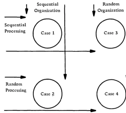
Sequential and random file organization should not be confused with sequential and random processing. The terms random and sequential, when used with the term processing, usually refer to the order of the input transaction records or to the order of reference to records in the master file. Figure 2 shows the relationship between file organization and data processing, as follows:
Case 1 Sequential processing of sequentially
organized data
Case 2
. Case 3
Case 4
Random processing of sequentially organized data
Sequential processing of randomly organized data
Random processing of randomly organized data
t
~
Sequential Processing
Random Processing
Sequential ~ Random
Organization Organization
8 8
8
---4 ..
~8
Figure 2. File organization and processing approaches
Tape and Card
Sequential
Records on tape and card files must be processed as they are encountered because of the physical nature of the storage medium. Therefore, tape and card master files, and their associated transaction files (regardless of the medium), tend to be sequential.
Random
[image:11.618.341.551.59.247.2]Direct Access Storage Device (DASD)
Sequential
In a sequentially organized DASD file, the records are stored in record control number sequence, so that records with successively higher control num-bers have successively higher address numnum-bers. Normally, the record control number is not the same as the address where it is stored; the only requirement is that the control numbers be in sequence and in sequential (not necessarily consecu-tive) disk storage locations.
Additions and deletions to the file present the greatest design challenge. Additions which cannot be inserted in sequence in the original (prime) area are known as overflow records. Overflow areas are set aside on specific tracks of the same cylinder, or, since it is difficult to predict the overflow
pattern, a single cylinder or group of cylinders may hold ·all overflow records for the entire file. As the number of overflow records increases, the proces-Sing time also rises. Therefore, it is customary to reorganize the file periodically, incorporating all overflow records into the prime area.
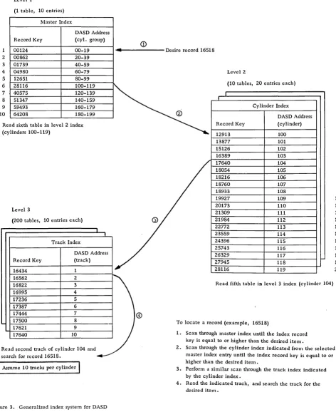
Although DASD sequential files can be processed strictly sequentially in the same fashion as tape, such a method does not take full advantage of the ability of the DASD to locate a specific record directly and thereby eliminate tlie time required to read inactive records. An index system is used frequent-ly to narrow the search for a particular record.
Such a system may be likened to the index system used in locating an item in a multiple-volume stand-ard dictionary. The index on the cover gives the last item in a volume. In a DASD the master index performs this function. The thumb index is similar to a cylinder index, while the upper-page index is analagous to the track index. The specific item is located by searching the page or track.
Each of these indices may be considered as a level. The number of levels and the size of the index is dependent upon the total number of items in the file. The indices usually are contained in the same or another DASD, and, if possible, the master and cylinder indices are read once into core and re-tained to minimize the retrieval time. The index itself is a table normally composed of at least two el-ements per entry: the record control key for the last record entry contained in the specific logical group (cylinder group, track group), and the DASD track address. Figure 3 illustrates the general scheme of an index system.
Because inactive records in a file may be skipped, the term skip sequential is used frequently to refer to the indexed sequential file organization methods. Specific sequential file organization techniques and
their related overflow record and index systems are discussed in section 2, under "Determination of File Organization" •
Random
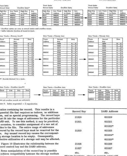
In a random file, records are stored at an address that is obtained by applying a mathematical formula to the record control field. No indices are required to locate a specific record, since the storage address can be found by using the same conversion routine.
Example:
Assume that three types of loans are to be stored on DASD as follows:
Type of loan DASD address
A
000600-034099B C
034100-047999 048000-059999
Number of available locations
33500 13900 12000 Apply the following formula to the loan account number to obtain the DASD address.
1. Multiply account number by the number of
available locations. Assume Type C account num-ber 99999.
99999 x 11999
=
11998880012. Add the lowest location of the allotted block to the five high-order positions of the product obtained in step 1.
11998 + 048000
=
0599983. Use the result from step 2 as the DASD address.
In the transformation of two different record control numbers, it is possible to obtain the same DASD address. Such duplicate addresses are called synonyms. If only one record can be stored at a given address, or if multiple records may be stored, and all available areas are used, the synonyms become overflow records. Address conversion routines and overflow techniques for randomly organized files are discussed in section 2 under "File Organization Techniques".
PROCESSING OF DATA FILES - INPUT/OUTPUT CONTROL SYSTEM (lOCS)
Definition
1
2
3
4 5 6
7
8 9 10
Levell
(1 table, 10 entries)
Master Index
DASD Address
Record Key (cyl. group)
00124 00-19
2 00862 20-39
3 01739 40-59
4 04980 60-79
5 12651 80-99
6 28116 100-119
7 40575 120-l39
8 51347 140-159
9 59493 160-179
10 64208 180-199
Read sixth table in level 2 index (cylinders 100-119)
Level 3
(200 tables, 10 entries each)
Track Index
DASD Address
Record Key (track)
16434 1
16562 2
16822 3
16995 4
17236 5
17387 6
17444 7
17500 8
17621 9
17640 10
Read second track of cylinder 104 and
search for record 16518.
I
Assume 10 tracks per cylinderI
Figure 3. Generalized index system for DASD
<D
... - - - Desire record 16518
®
Level 2
(10 tables, 20 entries each)
I
,
Cy linder Index
@
DASD Address
Record Key (cylinder)
12913 100
l3877 101
15126 102
16389 103
17640 104
18054 105
18216 106
18760 107
18933 108
19927 109
20173 110
21309 111
21984 112
22772 113
23559 114
24396 115
25743 116
26329 117
27945 118
28116 119
Read fifth table in level 3 index (cylinder 104)
To locate a record (example, 16518)
1. Scan through master index until the index record key is equal to or higher than the desired item.
2
3 4
5
6
7
8 9 10 11 12
13
14 15
16 17
18 19 20
2. Scan through the cylinder index indicated from the selected master index entry until the index record key is equal to or higher than the desired item.
3. Perform a similar scan through the track index indicated by the cylinder index.
[image:13.613.70.542.70.648.2]deblocking of data records, detection and error recovery procedures, and the overlapping of proces-sing with input and output functions. Through the use of pretested, error-free I/O routines, the pro-grammer has more time to concentrate on the data manipulation requirements of his specific program.
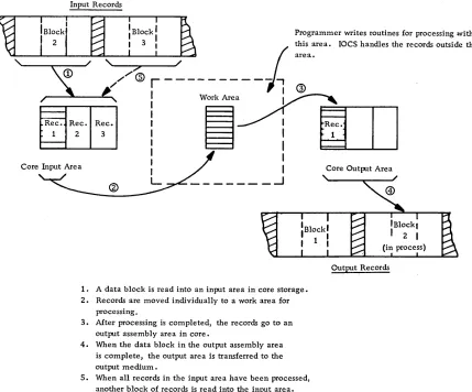
Functional Concepts
The general flow of data records from a blocked data
file through a program controlled by
lacs
isillus-trated in Figure 4.
Many modifications of this basic flow of data are possible. In some cases records are processed in the input area and transferred from there directly to the output area. In other cases records are read and written in the same area. Records also can be processed in the output area.
Usually, a unique device-error recovery routine exists for each class of I/O device. Upon detection of an error, such as a misread. misseek, etc., the appropriate error routine is entered, and an attempt is made to recover from the error (for example,
Input Records
reread tape, reseek, etc.). If recovery is not
pos-sible, various choices may be provided, such as bypass of the record or return of control to a user error procedure.
I/O devices may be attached to channels instead of directly to the central processing unit (CPU). Chan-nels provide paths for data transfer between the CPU and the I/O device. This allows I/O operations to be overlapped with CPU operations so that instructions can be executed simultaneously with data movement in the channels. For example, one channel may be reading data from an input file, another channel may be writing data on an output file, while a record that was read previously is being processed. This is often called read/write/compute overlap.
The amount of overlapping actually achieved (ef-fective overlap) is governed through the assignment of I/O areas and work areas. An I/O area (or buffer) is that area of main storage to which, or from which, a block of data will be transferred physically. A work area is an area used for processing an individ-ual record from the block of data. Overlap is most
effective, usually, when at least two
I/o
areas are, ' - - - - r - - - - J / '",-_...,.. _ _ ....J/
Programmer writes routines for processing within this area. IOCS handles the records outside this
I
area.~ '/~
~
, / &r---j
®
,r-....aR'-ec-. -R-I:e;"""'C:
!
W~O,k
Are~~ec.
2 3 I
I
1,
I
I I
Core Input Area ore tput Area
"
I C Ou
L _ _ _ _ _ _ _ --1
~-~--1. A data block is read into an input area in core storage. 2. Records are moved individually to a work area for
processing.
3. After processing is completed, the records go to an output assembly area in core.
4. When the data block in the output assembly area is complete, the output area is transferred to the output medium.
5. When all records in the input area have been processed, another block of records is read into the input area.
Output. Records
[image:14.612.45.474.337.693.2]assigned to each data file used by a program. When a request is received by lacs for an I/O operation, the requested operation is started, and control passes back to the problem (or user's) pro-gram, if the affected channel and device are not busy.
If the channel or device is busy, the request is placed
in a list of
I/o
requests (separate list or queue foreach channel), and the operation is performed as soon as previous requests have been handled.
On some computers the channels have the ability to interrupt processing at the completion of an I/O operation. The interrupt transfers program control to laCS, which examines the queue for the affected
channel. If the queue has no pending I/O request,
control is returned to the problem program at the
point of interruption. If, instead, a request is
pending, lacs starts the I/O operation and then re-turns to the problem program. If lacs fails to have an available area or record when one is required by the problem program, a force situation results. lacs is forced to suspend processing of the user's program temporarily until it can service the I/O demands. All operations are suspended, except channel operations in progress, until the needed channel interrupts the system, and laCS is able to resolve the situation by servicing the data file.
Programming Concepts
laCS is specified by the programmer at the symbolic
programming level. It is inserted automatically into
the user's program at compilation time and becomes an integral part of the user's program. In some cases standardized lacs packages may be used to avoid compilation time. For certain computer sys-tems, some of the lacs routines may be located in the operating system, which is supervising and controlling the tasks that a computer is to perform. When I/O operations are required, the problem program turns control over to the operating system, which performs the necessary I/O functions and returns control to the problem program.
To enable specific coding to be generated to per-form the lacs functions needed by a particular program, the programmer issues two types of statements (declarative and imperative) in his source program.
Declarative Statements
These statements, known also as DTF (Define the File) statements, or DD (Data Definitions), provide information that:
• Describes the characteristics of the logical file, such as blocking factor, record size, record format, type of labels, file name, etc.
• Describes the physical device on which the file resides, such as channel, type of device, etc.
• Identifies options to be taken under predefined conditions, such as uncorrectable read errors.
• Contains addresses of user-written routines, such as end-of-file routines.
Imperative Statements
Four basic verbs cause various laCS functions to occur when specified in a user's program - OPEN, GET, PUT,. and CLOSE.
OPEN does the following:
• Makes a data file available to a program. • Checks header labels on input files.
• Performs control functions as specified (re-wind, etc.).
• Writes header labels on output files.
GET causes a data record to be made available to the program, either in the input area or in a work area. Issuing a GET provides linkage to routines that can perform various necessary func-tions for input files, such as:
• Initiate read of data blocks into main storage as they are needed.
• Deblock data input records.
• Count data blocks and records read into main storage for comparison to equivalent count fields in the trailer label.
• Recognize and handle errors originating as a result of the I/O operation.
• Recognize an end of reel (EaR) condition; check the trailer label and, for tape, rewind and unload; read and check the header label on the next sequential storage medium unit (tape, pack, etc.).
• Recognize an end of file (EOF).
PUT causes a data record to be moved to the out-put area from the inout-put area or from a work area, or it may place the core limits of the record in a list containing the addresses of all records ready for output. Issuing a PUT provides linkage to routines that can perform various necessary functions for output files, such as:
• Block data output records.
• Initiate write of data blocks when they are as-sembled.
• Count data records and blocks for placement in count fields of the trailer label.
• Recognize the physical end of the storage
• Recognize and handle errors originating as a result of the I/O operation.
CLOSE does the following:
• Causes a data file to become unavailable to a
program.
• Writes any output records that may still be in the output areas.
• Writes trailer labels.
• Performs control functions as required (write tape marks, rewind, etc.).
Record Formats
In many files different record formats may have identical lengths, while other record formats may vary in length. However, when records of different lengths are grouped together to create a data file, only one format can be specified to laCS for the file. Unless every record (excluding header, trailer, and checkpoint records) in the file is of identical length, the file is considered to be composed of variable-length records. Unless all of the records in the file are unblocked, the file is considered to be composed of blocked records.
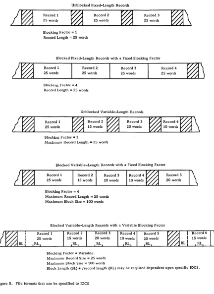
Various file formats can be specified to laCS (see Figure 5):
• Unblocked fixed-length records.
• Blocked fixed-length records with a fixed blocking factor. Padding may be used when insuf-ficient data records are available to complete the last block of a data file. A padding character, such as 9, is inserted, usually in each position of any
I
unused records in the last block. (Some laCS routines process a short block instead of using padding. )• Unblocked variable-length records. The length of an individual record must fall within a specified maximum record length established for each file.
• Blocked variable-length records with a fixed blocking factor.
• Blocked variable-length records with a variable blocking factor. Instead of using a fixed blocking factor, the records are assembled within a block so that their combined length does not exceed a speci-fied block length. Records are not split between blocks •
• Undefined records. This format permits handling of records that do not conform to the other formats.
Special fields may be required by laCS on some data records to aid in the deblocking process:
• A special character, usually a record mark, located in the last position of each record and con-sidered as part of the record.
• A record length indicator, containing the word or character count of the data record, located in the same relative position within each data record.
• A block length indicator, showing the number of words or characters in the block, used to ascertain that the correct block length has been brought into core.
Unblocked Fixed-Length Records
Record 1
2S words
Blocking Factor
=
1Record Length
=
25 wordsRecord 2
25 words
Record 3
2S words
Blocked Fixed-Length Records with a Fixed Blocking Factor
Record 1 25 words
Record 2
25 words Blocking Factor
=
4Record Length
=
25 wordsRecord 3
25 words
Unblocked Variable-Length Records
Record 1
25 words
Blocking Factor = 1
Maximum Record Length
=
25 wordsRecord 3 20 words
Record 4 25 words
Blocked Variable-Length Records with a Fixed Blocking Factor
Re.cord 1 25 words
Record 2
15 words
Blocking Factor = 4
Record 3
20 words
Maximum Record Length = 25 words Maximum Block Size = 100 words
Record 4
10 words
Blocked Variable-Length Records with a Variable Blocking Factor
Record 2
15 words
RL.
Record 3
20 words
RL
Blocking Factor = Variable Maximum Record Size
=
25 words Maximum Block Size = 100 wordsRecord 4
10 words
Record 5 20 words
[image:17.613.67.499.54.647.2]SECTION 2: DESIGN OF DATA FILES
Though the factors in determining the design of data files are presented separately in this manual, no one factor can be considered independently, since all factors are interrelated and must be weighed one against the other to select the best approach. Consideration must be given to the demands of the job, as well as to the hardware requirements.
DETERMINATION OF DATA
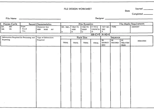
The first step in file design requires a study of all procedures that utilize the file. On the basis of the findings, record each necessary item on a worksheet similar to the one illustrated in Figure 6. Indicate type of information, frequency of occurrence, and sequence in source document, if applicable. The following should be done:
• Check that the necessary reference data is
included, if this is a source file.
• Weigh the effects of media storage costs vs program execution time for constant-type data, such as tax exempt dollars in payroll.
• Include fields obtained by processing, if the results must be recaptured later.
• Examine all applications that utilize the file to prevent omission of necessary data.
• Explore future requirements of the current procedures. For example, it might be judicious to
include an additional deduction field in a payroll
application.
• Determine any additional information needed for planned applications. It may be more practical to include an extra field now than to reorganize the files later.
• Study the feasibility of consolidating existing data files into a single data file to eliminate
duplication of common information, if such a
com-bined record would not too adversely affect the running time of the volume application.
• Ascertain that material needed in the new application, for which the data file is to be designed, is not available already in an existing data file •
• Verify that the data file, when set up, will contain all the basic information to meet the
FILE DESIGN WORKSHEET Started
Date
Completed _ _ _
File Name Designer
Process Cycle Record Characteristics File Dynamics File Media Requirements
DA MO Type: Character Size NO. REC. YRLY% YRLY% 5 YR% TOT NO. TYPE AMOUNT
WI< YR Fixed MIN MAX AV ADD DROP GROWTH REC
Var. A B C 0 E
5(B-C)=D. A+AD=E
Infonnation Required for Processing and Type of Infonnation Field Size Sequence
Reporting Required IN IN IN REMARKS
TRIAL TRIAL TRIAL FINAL SOURCE RECORD RELATED DOC Fll.ES
[image:18.617.50.545.356.707.2]requirements of all persons who will be using the end products resulting from the file processing.
• Add fields required for technical reasons, such as IOCS requirements for variable-length records •
• Consider file maintenance and audit control.
DETERMINATION OF FIELD SIZE
The number of positions required to record each item of information should be determined and entered on a form similar to that shown in Figure 6.
Determining Factors For Field Size (And Subsequent Record Length)
Type of Field
Control and indicative data field size should equal the total number of digits in the largest single item to be recorded in the particular field. Occasionally, to conserve storage, the high-order digits may be disregarded for a field, such as order number.
Quantitative data field size may equal the total number of digits in the largest amount to be record-ed, or the number of digits that will occur with reasonable frequency. Procedures can be developed to handle the rare exceptions. See Omission of High-Order Digit under "Field Compaction Technique s" •
Recording Medium
Since some media, such as cards and disks, con-tain a fixed number of positions per unit of storage
(disk sector or track, etc.), it is essential to consider this overall limit to design efficient and practical records.
Example:
Assume a DASD composed of 100-character disk sectors that can be read consecutively in blocks
of 200. If a disk record plans to 82 positions,
it would be better to reduce the record to 80 positions, since five such records would fit into four sectors with no unused positions. By beginning the first record of the file in an address divisible by four, no extra programming for hardware capability is required.
Processor Characteristics
The length of a field must be communicated to the equipment for proper handling of data.
Unit record or character machines, in which every position of core storage is addressable, impose few restrictions, since hardware charac-teristics, such as word marks or next non-number character, are utilized to control the movement of data.
In fixed-word-Iength machines, in which only a group of positions of core storage is addressable, size becomes critical. It is common practice to
pack two or more fields into a single word, but if
the fields require different signing, special con-sideration is necessary, since normally provision is made for only one sign per word. Also, it may be more costly in time to extract portions of words or bridge words (one field to two words). Depending upon the computer, alphabetic data may require two core storage positions. Normally, alphabetic and numeric data cannot be stored in the same word unless both are treated alphabetically. The tradeoffs between time, core storage, and media storage must be kept in mind. Some computers possess the characteristics of both character and fixed-word-Iength machines, thereby making possible complete flexibility of design.
File Size (Total Number of Records)
Since the field size affects the total record size, all unnecessary positions should be eliminated to decrease I/O time and storage media requirements.
Future Requirements
If the demands to be placed on the information
indi-cate that the need for another position is impending, it would be easier to incorporate the additional character in the design phase so as to avoid rewiring or reprogramming and a patched-Up record layout.
Field Compaction Techniques
Because a reduction in the length of a record pro-duces such positive results as an increase in DASD packing and a decrease in time to read and/or write, field compaction techniques should be investigated and the cost of the technique evaluated as each file is designed. Some methods to consider for reducing the number of positions are:
• Decimal Scaling
significant digits is known as the decimal scaling factor. This factor must be known and considered for manipulation of the data. It is negative if the new decimal point is moved to the right; it is positive if the decimal point is shifted to the left.
Example:
Unscaled Scaled Scaling
Variable Number Number Factor
X .00123 .123 -2
Y 100.00 .100 3
Z .987 .987 0
All factors of X would have a -2 scaling factor.
All factors of Y would have a 3 scaling factor.
All factors of Z would have a 0 scaling factor.
If X and Y were multiplied, the product would have a
scaling factor of 1 (3-2).
• Floating-Point Numbers
The difference between decimal scaling and floating point is that in the former the number of zeros omitted is fixed for all numbers represented in a given field. In floating point, each individual number is transformed into two parts: the significant
digits, known as the mantissa, and the variable number of zeros needed to position the significant digits, known as the characteristic. Both mantissa and characteristic are carried in the record. In fixed-word-length machines, a constant is often added to the characteristic so that it can be treated as a positive value. This leaves the sign position free for the mantissa. Either program subroutines or floating-point hardware are capable of handling such numbers.
Example:
Assume an 8-position mantissa and a 2-position characteristic in a 10-position fixed word.
Actual No. of pos. + = Floating-point
number Mantissa dec. moved Constant Char. number
0000.0004583 .45830000 -3 50 47 +4745830000
-1396.430000 .13964300 4 50 54 -5413964300
0000.321659 .32165900 0 50 50 +5032165900
• Omission of High-Order Digit
In quantitative fields, when the maximum number of
digits rarely occurs, the field length can be shortened. When significant digits do occur, an overflow condition results. Computers will turn on an overflow indicator, which can be tested, and an alternate subroutine can be executed when applicable.
In media storage, the overflow digit can be repre-sented by some type of zoning, such as x overpunch in cards or AlB bits over the high-order position, as in 1400-series computers. This is typical of the flagging compaction technique, where the use of a character replacement indicates a given following condition within a field.
• Variable-Length Fields
Only significant digits are recorded, and fields are separated by a special symbol, such as plus or minus. The number of fields for a given record is constant, and each field is identified by its position within the sequence. A small routine in the computer expands each field to the required size. Savings are greatest when the total of the average number of significant digits plus one for each field is less than the sum of the maximum field sizes. This technique is of greatest value for input preparation, where transmission line cost and transcription time can be reduced by its use. This is an example of the marking cc;>mpaction technique, which uses a special mark or symbol to indicate the beginning or the end of a given condition.
• Bitting
Multiple items can be stored in a character or group of characters by partitioning into bit notation, where each bit has a specific value or control function. Thus, bit 1 may represent active or inactive; bits 2 and 3, one of four credit ratings; and hits 4 and 5, one of four age classifications. Care must be taken not to develop combinations that are invalid to a particular hardware system.
• Coding
Coding may be used to replace a larger field. During processing, the codes can be interpreted or trans-lated to the constants they represent. For example: a one-position code may represent the unit of measure of inventory items--a 1 for dozens; a 2 for ounces; a 3 for pounds; etc.
• Heading
Heading takes advantage of redundant information. Thus, one header containing information common to a series of items can precede its respective de-tail items. For example: spread input records, such as might be used in a billing
operation--date/order no. Icust. no. litem 1/item 2/----/item nl
• Substituting
Substituting makes use of the number of free bits that appear in a given character set or, in the case of EBCDIC, some of the less used combinations, such as the lower case alpha representations. One of these characters replaces more than one other character, primarily numeric pairs. For example, to reduce month from a two-digit numeric code, the letters A and B can be substituted for November
• Table Lookup
Use of table-lookup techniques--whereby such fac-tors as rates, constants, or other types of informa-tion are stored in core in table form--permits a given field to be reduced to a code. This differs from straight coding methods that substitute codes permanently for given values, because it allows the shortening of a data field without precluding retrieval of the longer values that the codes represent. The size of the table is limited only by the storage capacity of the system involved.
Example:
Use of code for a management budget report.
Table
Search Argument Table Argument Function
(coded input field) (same coded data (expanded field
normally stored in information)
ascending or descend-ing sequence)
101 (dept. code)
,
100 Accounting",,~ 101 Accts. Receivable J
102 Accts. Payable
103 Internal Audit
Coupled with an error routine for unlocated search arguments, table lookup also serves as an excellent validating tool.
• Binary
The binary system uses only two symbols (0 and 1) as opposed to ten symbols (0-9) for the decimal system. Since the position value of these digits is based on the powers of 2 rather than of 10, the units position of a binary number has the value of 1; the next po sit ion , a value of 2; the next, 4; the next, 8; the next, 16; and so on.
8 7 6 5 4 3 2 0
2561 1281 641 321 161 81 41 21 11
Place value of binary numbers
4 3 2 0
10,0001 10001 1001 101 11
Place value of decimal numbers
The decimal number 20 expressed in binary would be 10100 or (1 x 24) + (0 x 23) + (1 x 22) +
(0 x 21) + (0 x 20) or (1 x 16) + (0 x 8) + (1 x 4) +
(0 x 2) + (0 xl).
Since binary notation requires only two symbols, one bit can be used to represent each place value of a number. In standard decimal format (BCD or EBCDIC), six or eight bits are required for each place value of the number. (Refer to Figure 27. ) Thus, in binary the eight bits 11111111 represent the decimal number 255. Relating this to media or core storage capable of handling eight bits per unit of storage (one column on tape, one byte in core, etc. ), only one unit is required for binary, whereas three are needed for decimal. Binary notation is a very effective compaction technique for numeric data, providing the computer characteristics lend themselves to efficient handling of such data.
• Hexadecimal
Hexadecimal uses a base 16 (as opposed to 2 and 10 for binary and decimal respectively) and 16 symbols
(0-9, A-F). It is used mainly as a compact notation
for binary to facilitate man-machine communication. Any four digits of binary have a maximum value of fifteen. Therefore, one hexadecimal digit can be used to represent four binary digits. To illustrate:
2F 0010 1111 47
hex • binary decimal
• Packed Numeric Format
Numeric data represented in BCD or EBCDIC re-quires only four bits (1, 2, 4, or 8) to represent its value. In storage units capable of handling eight bits per unit of storage, the packed numeric format takes advantage of this characteristic by placing two numeric characters into one unit of storage. To illustrate:
Example of numeric
Packed representation in packed
8-bit code format format
C C 0 1 } check bit
0 8 1 0
1 4 0
numeric 0 numeric
2 2 0 value of 9 1 value of 3
3 1 1 1
4 8 0 0
I
5 4 1
numeric 1 numeric
6 2 1 value of 7 0 value of 5
7 1 1 1
To operate most efficiently in packed format, the computer should contain in its instruction set codes to pack and unpack, as well as to operate arith-metically when in the packed mode.
Evaluation of Compaction Techniques
A given compaction technique must be evaluated for:
1. Amount of memory (core) required to hold
the endode-decode instructions
2. Encode-decode subroutine timing requirements 3. Compaction percentage acheived
4. Compatibility with programming systems 5. Retention of collating sequence
6. Retention of fixed field length
7. Effect on the overall system, including
related clerical functions
For a discussion in depth of compaction techniques, see Record Compaction Techniques (E20-8252).
DETERMINATION OF DATA SEQUENCE
Data sequence is most critical for those files that work with source documents. Card punching, terminal operation, etc., being manual operations, are subject to the greatest variation in rate of production. Anything that simplifies these functions tends to ensure a faster and more accurate operation. The following are points to bear in mind:
• Recording of data in the same order as that in
which it is normally read. If the data sequence is
considerably different from that on the source document, it may be necessary to redesign the
source document and retrain personnel. If the file
is to be used as input to a serial I/O unit, such as tape to card, the sequence is dictated mainly by the sequence desired on the output unit.
• Location of like fields in the same relative record posItions in files that work together. This assures that sorting and controlling can be accom-plished if the file is contained in cards; it also facilitates programming.
• Placement of sorting fields adjacent to one another, with the minor code on the right and each progressively higher code to the left. Although sort programs can operate on multiple-control fields, time is used to extract and combine fields into a single key.
• Availability of results supplied by machine to serial output unit.
• Compatibility with computer characteristics so that data sequence does not affect processing speed. For example, with the 1400 series, field sequence, size, and grouping determine whether instruction chaining can be used.
• Arrangement of alphabetic/alphameric data in
one area of the record. This facilitates handling
of data, particularly in fixed-word machines, and permits minimum core and media requirements.
• Frequency of occurrence of each field. If it is
decided to use variable-length records because some fields are not present in all records, the variably occurring fields should be last in the record to keep the fixed fields in the same relative location on each record.
• Adherence to requirements of programming systems. For example, the block-length field specified for variable-length records normally must be the first field in the block.
DETERMINATION OF FILE ORGANIZATION
For strictly card- and/or tape-oriented systems, file organization normally is sequential. Therefore, the following discussion is oriented mainly toward the design of DASD data files.
Sequential vs Random Organization
Sequential Advantages
• Both sequential and random transactions can be handled effectively in most cases.
• Reports arranged in data file sequence can be obtained without sorting .
• Control over both the processing and the stored file can be more positive.
• Less medium storage space is required.
-1 • Frequently the entire file need not be on line
simul taneously.
Sequential Disadvantages
• More core storage may be required because of index handling routine s.
• Process time is greater for random input be-cause of index file seeking and processing.
Random Advantages
• Less core storage is required normally. • Process time is less for random input.
Random Disadvantages
• To maintain access requirements, frequent
reorganization may be necessary if the file is
dynamic.
File Organization Techniques
Sequential Techniques
• Control Sequential
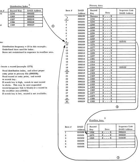
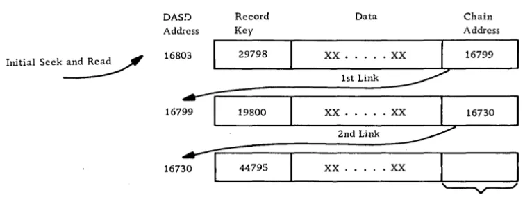
Records are written initially on the DASD file in a sequential manner in the primary file area. As new records are inserted into the file, they are written into available record space in a separate overflow file area. Every record in a control sequential file must have a sequence linkage field, which contains (when required) the actual DASD address of the next sequential record. This field is utilized in a record in the primary area only when the next sequential record is stored in the additions area. All records in the additions area utilize the sequence linkage field, which shows whether the location of the next sequential record is in the additions or the primary area. A dummy record is the first record in the data file to permit additions with lower re-cord keys. As the file is loaded, a distribution index is created, which makes it possible to locate records at random. The index is a single-level index that contains the record control key and the DASD address, from selected records located in the file. The frequency of the entries can be chosen to satisfy the control and retrieval needs of the application. The first and the last entry in the file are always given. The addition of overflow records does not affect the index unless a record higher than the last record in the file is to be added. (See Figure 7.)
Control sequential files are reorganized periodi-cally to reduce access time for all records in the file. Reorganization results in the placement of all records sequentially in the primary area, with the entire additions area and all sequence linkage fields cleared.
This method should be considered where pro-cessing is primarily sequential, with some random
input where access time is not critical. It is
supported by IBM Programming Systems (load, add, tag for deletion, delete, and unload programs) for the 1401, 1440, and 1460 Data Processing Systems with the IBM 1311 or 1301 Disk Storage Units
(except for the 1301 on the 1401). For further informa-tion refer to 1401/1440/1460 File Organizainforma-tion
Specifications (C24-3185).
• File Organization System
The File Organization System (FOS) is supported by the IBM 1410/7010 Operating System, which provides programs to load and maintain files for the IBM
1301 and 1302 Disk Storage Units. This technique uses a two-level index (cylinder and track), although a third level (master) is generated if the cylinder index grows too large. All overflow records cause
an entry into the track index. Therefore, no se-quence 'link field is required to retrieve overflow records. (See Figure 3.) For further details refer to 1410/7010 File Organization System (C28-0405) .
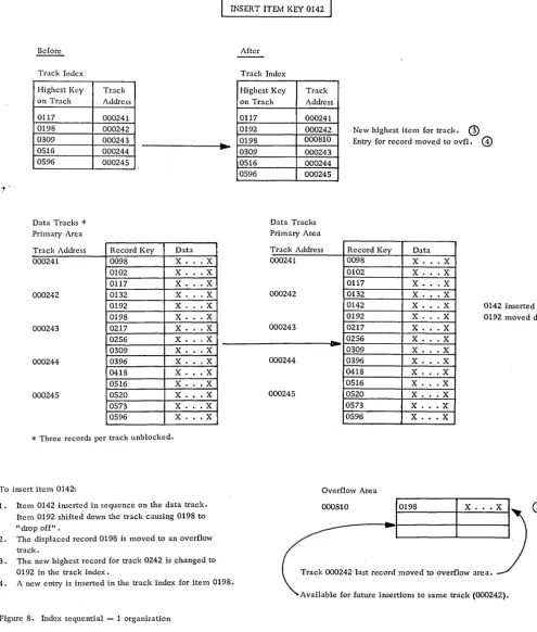
Index Sequential -- 1. In this method, additions are inserted in the data file in their correct sequential location by moving the records with higher keys down the track. This may result in the shifting of a record from the end of the track into an additions area. The most practical location for the additions area is in a single overflow area, although it is pos-sible to leave the tracks unpacked or to create an additions area within each file cylinder, provided that an even distribution of additions is antiCipated.
Normally, at least two levels of index files (cyl-inder and track) are created, although with larger files, a master cylinder index may be warranted al-so. A new entry must be made into the track index whenever a record is moved to the additions area. This method is effective for the storage of sequenced files of fixed-length unblocked records with the IBM 1301 or 2302-1 and 2 DASD units. The technique is not program-supported. For an example of the use of Index Sequential --1, see Figure 8.
Index Sequential -- 2. Records are stored in se-quence by their record key, and their processing and location are controlled by a two- or three-level index.
1. Level 3, or master index, is not required but
reduces search time when a number of cylinder in-dex tracks occur. Each entry consists of a specific cylinder index track address and the highest key present in that track.
2. Level 2, or cylinder index, must exist. Maintained in record key sequence, each entry con-tains the highest record present in each data file cylinder, as well as the track address of that cy-linder's level 1 (track) index.
3. Levell, or track index, must exist in each cylinder used to store data file records. There are two entries for each track in the primary area:
a. Normal entry, which contains the key of the last record and the address of the first record on the track.
b. Overflow entry, which contains the high-est key of an overflow record from a prime data track, along with the address of the overflow record with the lowest key •
The index sequential -- 2 technique combines the insertion technique of the index sequential -- 1 method with the concept of chaining for the records
that are shifted to the additions area. An addition
Distribution Index
Item # Record Ke DASD Address
First 1234 000200
9 1269 000208
19 1327 000218
29 1384 000228
Last 1389 000229
Note:
1. Distribution frequency
=
10 in this example.2. Underlined item used for index.
3. Items not maintained in sequence in overflow area.
To locate a record (example 1273)
CD
Read distribution index, and select properentry point to primary file (000208).
@ Read record at entry point, and match
to search key.
G>
U search key is high, match to next record in chain. This may be next sequential record (sequence link is blank) or a record in the overflow area (10101).@ U search key is low, record is not available.
Figure 7. Control sequential organization
This causes the last record on the track to be moved to the additions area, along with a linkage field. The overflow entry of the track index is up-dated. Thus, the records in the primary area tracks are in sequence with keys lower than any that have overflowed that track. The overflow area
Pri m ary Are a
Item # DASD Record Sequence Link
Address Key Data DASD Address
2.
000199 000200 1234 Dummy X . X. . X .X2 000201 1235 X. · . X
3 000202 1:246 X. .X
4 000203 1248 X. .X
5 000204 1250 X. · . X
6 000205 1256 X. · . X
7 000206 1257 X . . .X
8 000207 1259 X. · . X
_9_ 000208 1269 X. .X 010101
1\
10 000209 1276 X. .X
11 000210 1277 X .•• X
12 000211 1279 X. · . X
13 000212 1290 X . . .X
14 000213 1297 X . . .X
15 000214 1301 X . . X
16 000215 1312 X . . X
17 000216 1314 X. · . X
18 000217 1324 X . . . X 010102
...!2.... 000218 1327 X. · . X
20 000219 1328 X. · . X
21 000220 1329 X . . X
22 000221 1356 X. · . X
23 000222 1358 X. .X
24 000223 1359 X . . X
25 000224 1365 X . . X
26 000225 1369 X. .X
27 000226 1377 X. .X
28 000227 1379 X . . .X
~ 000228 1384 X. .X
30 000229 1389 X. .X
--@
3 Overflow Area
Item # DASD Record Sequence Link
1
2 3 4 5 6
Address Key Data DASD Address
010100 _ 1326 X. .X 000218
010101 1273 X. .X 000209
010102 1325 X. .X 010100
010103
)
010104 010105
®
contains records in sequence by time of arrival but retrieved in record key sequence for any given track by use of the sequence linkage field and overflow entry in the track index. (See Figure 9. )
[image:24.612.53.547.46.615.2]INSERT ITEIv1 KEY 0142
After