IJEDR1601065
International Journal of Engineering Development and Research (www.ijedr.org)411
Computational Analysis and Optimization of Two
Phase Water Jet Machining
1
Revendra Kumar Deshmukh,
2Ashutosh Dwivedi
1Mtech Scholar,2Associate Professor 1,2Mechanical Engineering Department,
1,2Vindhya Institute of Technology and Science, Satna, Madhya Pradesh, India
________________________________________________________________________________________________________
Abstract - Abrasive water jet (AWJ) machining has found to been a most promising candidate in the field of advance machining technology and have considerable distant advantages over other machining technologies such as no thermal consequence, high flexibility and machining versatility, and small cutting forces. In the recent decades, anomalous research has carried in the field of cutting material such brittle, ductile as well as composite material using water jet. But there are still various research gap in the field of AWJ machining.
In this paper computational model the nozzle design of the AWJ has been analyzed with two phase flow (liquid -solid) in detail using a control volume approach within ANSYS, such that the performance of AWJ machining can be optimized. Effect of various parameters such as convergence angle, jet diameter ratio, and operating pressure effect on pressure, velocity, turbulent intensity, skin friction of AWJ has been examined and on basis of characteristics optimized nozzle of AWJ has been proposed. Before optimization the validation of work has been done with the available literature and found that the obtained results are within acceptable limit. Moreover, a new design of nozzle has been proposed which yields better performance in cutting.
IndexTerms - Jet diameter ratio, Nozzle convergence angle, skin friction, Turbulence Intensity.
________________________________________________________________________________________________________ I.INTRODUCTION
Abrasive particles, plays significant role in the material processing industry. Similar to laser cutting instruments they are precise, effortlessly supervised and cause scanty loss of material. On the other hand, abrasive jet machining does not engage high temperature, which is chief characteristic to laser cutting, and due to this it can be applied for machining of any material. Therefore, jet cutting can be employed in a wide range of industries, ranging from small machine shops and quarries, to large sheet metal, composites or ceramic processing in the car and aircraft industries.
II.LITERATURE REVIEW
Soiores et al. 1996 optimize the AWJ cutting technology for ceramics, experimentally by using statistical design principles. A new cutting head oscillation technique has been employed and it has found that the cutting quality improves by 30%.
El-domiaty an rahman 1997, developed abrasive waterjet model using two elastic-plastic erosion models. The model is valid only for brittle material. The model has ability to predict depth of maximum depth of cut on the basis of fracture toughness and hardness. Moreover, parametric analysis has also been carried in order to investigate the parameter affect on maximum depth of cut.
Hassan and kosmol 2001, develop a FEM model for AWJM in explain the work piece- abrasive particle interaction. The model can predict the depth of deformation consequently due to abrasive particle impact. The main aim of the develop model is to predict the depth cut without performing experimentation. In the results the dynamic behavior of the AWJ has been explored and the results are compared with the experimental work and shows good consistency.
Wang 2002 develop a semi empirical model for abrasive waterjet (AWJ) cutting of composite layered materials. During cutting of laminates, it starts delaminating form layer to layer, which results in failure of cutting process. Using the developed model, the depth of jet penetration can be determined and the performance can be enhanced during cutting process.
Wan and lim 2003, analyze transient flow in abrasive suspension jet cutting machines. The effort has been made in order to explore the problem of line and nozzle clogging, which would be overcome by the higher operating pressures and the employing smaller nozzles for fine-beam systems.
Chen and siores 2003, investigates the characterization of different materials' cut surfaces using a scanning electron microscope. The effect of abrasive particle distribution in the jet on striation development has discussed and examined by means of laser Doppler anemometry.
Liu et al. 2004, using CFD an ultrahigh velocity waterjets and abrasive waterjets (AWJs) model has been modeled using Fluent. The model consist of 2 and 3 phase flow condition in which water and abrasive particle where allowed to flow at different velocity and volume fraction.
IJEDR1601065
International Journal of Engineering Development and Research (www.ijedr.org)412
limiting conditions (high jet feed rates) of the model. Once this is found, the jet footprint can be predicted accurately for any jet feed speed.Baisheng et al. 2011, perform numerical simulation for inside flow field and outside high pressurized AWJ nozzle using ANSYS fluent. The obtained result shows that shock zone and wall jet zone in the external flow field of nozzle, there exist free jet zone; the section of abrasive jet farther from the target wall is of free jet structure; the shock pressure field on the target wall is standard distribution; the best shock range is 2-7 times the exit diameter of nozzle; the shock pressure of jet is proportional to the inlet pressure, and is inversely proportional to the range.
Radim et al. 2013 investigates the cut wall during AWJ process of non-corroding steels treated by cryogenic temperatures in liquid nitrogen. They reveal that the cryogenic temperatures significantly influence the material structure and respective properties. The main aim of their work is to enhance the material reliability in a wide range of production systems and operation conditions.
Anwar et al. 2013, use finite element (FE) method for AWJ foot print in which modelling, simulation and validation has been done for various transverse speed and pump pressure. The obtained result of material removal rate is compared with experimental data and the profile of kerf formation has also been examined.
Wang et al.2014 conducts experimental investigate to explore the effect of different process parameters such as jet impact angle, standoff distance, water pressure, abrasive particle diameter on material removal rate, removal depth and surface roughness for hard and brittle material, the alumina ceramic are used as base material.
Shiou and Asmare 2015, presents surface roughness improvement of Zerodur optical glass by means of an innovative rotary abrasive fluid multi-jet polishing process. Even though tauguchi approach has also been implement. It has observed that 98.33% improvement in surface roughness has been achieved and the factors effecting the surface roughness has also been discussed.
III.MATHEMATICAL MODELING
(In system Abrasive jet machiningis been analyzed with different aspect ratio. The wall shear stress is analyzed during cuting process and the effect of nozzle convergence with jet diameter ratio has also examined, in additional to varying the orientation also the heat transfer and shear stress is taken in consideration with the wall surface of the nozzle.
The equations governing this problem are those of Navier-Stokes along with the energy equation. The Navier-Stokes equations are applied to incompressible flows and Newtonian fluids, including the continuity equation and the equations of conservation of momentum on the x and y
According to equations
2 1 1
1 2
1 2
2 2
1 1
2 2
2 1 2
1
(
)
u
u
u
u
u
t
x
x
u
u
g
T
T
x
x
x
1 * * 2 * * 1 20
u
u
x
x
x1 momentum equation
1
* * * * *
* *
1 1 1 1 1
1 * 2 * * * *
1 2 1 2
*
Pr
*
u
u
u
p
u
u
u
u
t
x
x
x
x
x
x2 momentum equation
1 2 * * * * * * *
2 2 2 2
1 * 2 * * * *
1 2 1 2
2
*
Pr
*
Pr
*
u
u
u
p
u
u
u
u
t
x
x
x
x
x
Gr
T
Energy equation* * * 2 * 2 *
* *
1 * 2 * *2 *2
1 2 1 2
*
T
T
T
T
T
u
u
t
x
x
x
x
Since in order to check the accuracy of developed computational model which is coupled with Navier stokes equation and additional boundary conditions are provided through which heat transfer and mass flow, stress, etc other parameters are calculated and contour figures are generated and illustrated in the in this paper
IV.METHODOLOGY
IJEDR1601065
International Journal of Engineering Development and Research (www.ijedr.org)413
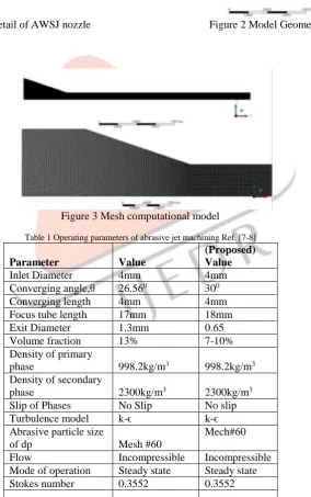
equation. In ANSYS 14.5 computational model has been developed in geometrical section with given geometrical parameters from the base paper i.e. [7-8]. After that the geometrical model is extended to mesh section in which complete geometry of AWJ is discretized into various numbers of nodes and elements i.e. (27,857 and 27,456) using mapped meshing the detail of meshing is given in figure 5.2. Moreover, the geometrical mesh model is further named such inlet, outlet, axis, wall section, etc. so that proper boundary conditions can applied in order to evaluate performance characteristics of Abrasive water jet machining.Figure 1 Computational model detail of AWSJ nozzle Figure 2 Model Geometry
Figure 3 Mesh computational model
Table 1 Operating parameters of abrasive jet machining Ref. [7-8]
Parameter Value
(Proposed) Value
Inlet Diameter 4mm 4mm
Converging angle,θ 26.560 300
Converging length 4mm 4mm
Focus tube length 17mm 18mm
Exit Diameter 1.3mm 0.65
Volume fraction 13% 7-10%
Density of primary
phase 998.2kg/m3 998.2kg/m3
Density of secondary
phase 2300kg/m3 2300kg/m3
Slip of Phases No Slip No slip
Turbulence model k-ϵ k-ϵ
Abrasive particle size
of dp Mesh #60
Mech#60
Flow Incompressible Incompressible
Mode of operation Steady state Steady state
Stokes number 0.3552 0.3552
IJEDR1601065
International Journal of Engineering Development and Research (www.ijedr.org)414
Water is as incompressible fluid; Abrasive particles are looked upon as rigid spherical small equal diameter particles, and there is not mass exchange between the liquid and solid;
There is not heat exchange between liquid-solid two-phase flow and outside, and the temperature is not change; Liquid-solid two-phase flow is steady turbulent flow.
.
V.METHODOLOGY
(The equation of motion of abrasive water jet machine is solved by using control volume approach and all the governing
equation are solved by using ANSYS- Fluent solver in which all the partial differential continuity and momentum equation are solved by iterative process till all the solution gets converged.
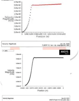
In order to validate the present work a computational model of abrasive water jet machine has been developed and compared with the available literature of Numerical Simulation and Experimental work of Huang et al. [7-8] and found that the obtained results are within acceptable limit and showing same trend as shown in figure 4.
IJEDR1601065
International Journal of Engineering Development and Research (www.ijedr.org)415
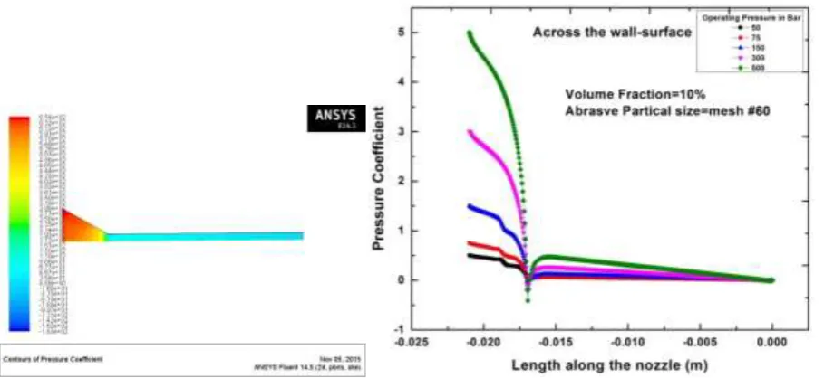
Figure 5 counter of pressure coefficient Figure 6Variation of Pressure across the wall surface coefficient with respect to nozzle length
Figure 6 demonstrates the pressure distribution across wall surface along with the length of the nozzle corresponding to the various operating pressures. It has been examined that as the operating pressure enhances the rate of pressure drop across the axis and wall surface significantly increases. It has also been scrutinized that the foremost drop in pressure across the axis and the wall surface is in the region where nozzle cross section changes i.e. from convergence region to Focal region.
From this it can be also be revealed that on changing the sudden cross section abrupt change drop in pressure takes place. The same representation has been seen in figure 5.
Figure 7 Contour of skin friction coefficient Figure 8 Variation of skin friction coefficient with respect to nozzle length
Figure 8 shows the variation of skin friction coefficient with respect to nozzle length. It has been found that on increasing the operating pressure, skin friction coefficient drastically increases till it reaches the peak and then there is a significant drop and get constant. This is due to change in cross section from converge region to focal region. Since the skin friction coefficient is proportional to flow Reynolds number and corresponding to flow velocity.
IJEDR1601065
International Journal of Engineering Development and Research (www.ijedr.org)416
Figure 9 Variation of turbulent intensity at 400bar
Figure 9 shows the turbulence intensity along the length of the nozzle corresponding to various inlet operating pressure. It has been observed that with increasing operating pressure, turbulence intensity significantly increases. In figure 9 the turbulence intensity reaches its peak value at the narrow region just before the start of focus tube length and in the focus tube the turbulence intensity has approximately been constant throughout the focus tube length. It can be seen in figure 9
From the above, it can be revealed that on changing section significantly increase change in turbulence intensity takes place in the critical region.
Figure 10 Variation of skin friction coefficient across the axis jet diameter ratio
Figure 10 shows the variation of skin friction coefficient across the axis jet diameter ratio. It has been observed that on increasing jet diameter ratio skin friction coefficient decreases linearly. Moreover, on increasing operating pressure the rate of decline in skin friction is more significant for lower operating pressure. This is due to increase in the jet diameter ratio means the surface area increases the pressure decreases and leads to decreases in skin friction.
IJEDR1601065
International Journal of Engineering Development and Research (www.ijedr.org)417
Figure 11 Variation of velocity magnitude with respect to jet diameter ratio
Figure 11 demonstrates the variation of velocity magnitude with respect to jet diameter ratio. It has found that with increasing jet diameter ratio the velocity linearly increases. However, also on increasing operating pressure the velocity increases. This is due to pressure is inversely proportional to velocity and at the exit velocity increases as per continuity equation Av=const as conferred by Bernoulli equation.
It can also be revealed that the velocity magnitude at 400bar is 15.98% more as compared to 300bar. Whereas, the rate of enhancement of velocity at 300bar is 4.92% and 5.69% at 400bar as jet diameter increases. From this it is clear that as the operating pressure increases this rate of enhancement of velocity significantly increases.
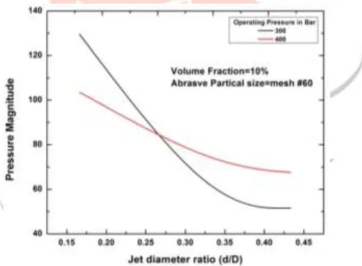
Figure 12 Variation of pressure magnitude with respect to jet diameter ratio
Figure 12 illustrates the pressure magnitude with respect to jet diameter ratio. From the above figure it is clear that an increasing the jet diameter ratio the pressure significantly decreases. This is because of increase in area leads to decrease in pressure. Therefore, pressure magnitude decreases less radically as operating pressure increases.
IJEDR1601065
International Journal of Engineering Development and Research (www.ijedr.org)418
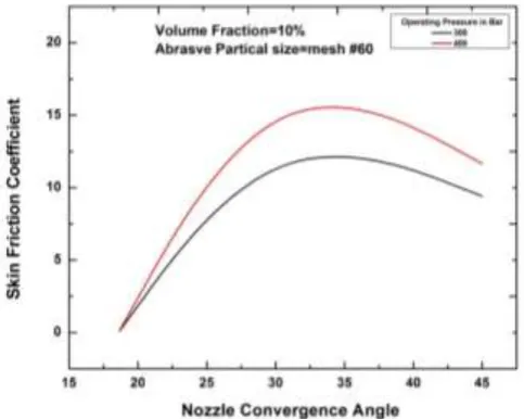
Figure 13 Variation of skin friction coefficient with respect to nozzle convergence angle
Figure 13 demonstrates the variation of skin friction coefficient with respect to nozzle convergence angle. It has been observed that on increasing nozzle convergence angle the skin friction coefficient across the wall surface first increases till 350 and then starts decreasing. At high operating pressure the rate of skin friction is remarkably more.
At higher operating pressure leads to higher level of kinetic energy along the flow paths with higher velocity. Therefore, higher the velocity contributes to higher skin friction coefficient at the wall.
Figure 14 Variation of velocity magnitude with respect to nozzle convergence angle
Figure 14 illustrates the variation of velocity magnitude with respect to nozzle convergence angle. It has been found that on increasing convergence angle velocity of the nozzle significantly decreases. This is because of loss in fluid flow energy due to flow loss i.e. sudden contraction. Moreover, at high operating pressure results higher velocity as discussed previously.
It can also be concluded that an increasing 141.28% nozzle convergence angle from 18.650 the velocity of the nozzle significantly decreased by 12.194%-13.908% respectively.
IJEDR1601065
International Journal of Engineering Development and Research (www.ijedr.org)419
Figure 15 Variation of pressure magnitude across the axis with respect to nozzle convergence angle
From the above figure it can also be examined that on increasing operating pressure 33% pressure magnitude across the axis increased by 35.41% and on increasing convergence angle this pressure magnitude amplifies to 41.92%-51.436%.
Figure 16 Variation of turbulent intensity across the axis and the wall surface with respect to nozzle convergence angle
Figure 16 illustrates the variation of turbulent intensity across the axis and the wall surface with respect to jet diameter ratio. It has been observed that on increasing nozzle convergence angle the turbulent intensity across the axis decreases till 300 and then starts increasing significantly at volume fraction of 10%. It has been also examined that the rate of decline in turbulent intensity across the axis is decreases as the operating pressure increases.
It can been also revealed that the turbulent intensity across the axis gets optimum at 300 and then starts, increases whereas across the outlet the rate in increment in turbulent intensity significantly less as compared to the turbulent intensity across the axis.
Figure 17 Variation of turbulent intensity across the axis and the wall surface with respect to jet diameter ratio
IJEDR1601065
International Journal of Engineering Development and Research (www.ijedr.org)420
axis decreases as operating pressure increases. It has been also revealed that at higher values of the jet diameter ratio the turbulent intensity across the axis get constant. But across the outlet the turbulent intensity decreases continuously)VI.CONCLUSION
‒ Increasing operating pressure increases cutting velocity of the nozzle.
‒ Skin friction coefficient increases as operating pressure increases. At the critical region i.e. region between convergence and focal region the skin friction coefficient reaches its peak and suddenly decreases and get constant in focal region of the nozzle.
‒ The turbulent intensity within nozzle is highest at the critical region and it increases as operating pressure increases. At the focal region the turbulent intensity remains constant.
‒ On increasing jet diameter ratio skin friction coefficient decreases linearly. Moreover, on increasing operating pressure the rate of decline in skin friction is more significant for lower operating pressure.
‒ It has found that with increasing jet diameter ratio the velocity linearly increases. However, also on increasing operating pressure the velocity increases.
‒ Increasing the jet diameter ratio the pressure significantly decreases. This is because of increase in area leads to decrease in pressure. Therefore, pressure magnitude decreases less radically as operating pressure increases.
‒ It has been observed that on increasing nozzle convergence angle the skin friction coefficient across the wall surface first increases till 350 and then starts decreasing.
‒ It has been found that on increasing convergence angle velocity of the nozzle significantly decreases. This is because of loss in fluid flow energy due to flow loss i.e. sudden contraction. Moreover, at high operating pressure results higher velocity as discussed previously.
‒ The turbulent intensity across the axis decreases significantly as jet diameter ratio increases and get constant when at higher at jet diameter ratio. While, the outlet the turbulent intensity continuously goes on decreasing.
‒ It has been observed that with increasing nozzle convergence angle pressure increases linearly. This is because of decrease in area leads to increase in pressure across the axis of the nozzle.
‒ On apply the proposed design the nozzle performance can enhance by 18-22% in all aspect such as enhancement in jet velocity, reduction in skin friction and can be operated at wide range of high pressure i.e. 500bar.
REFERENCES
[1] E. Siores, W. C. K. Wong, L. Chen, J. G. Wager, “Enhancing Abrasive Waterjet Cutting of Ceramics by Head Oscillation Techniques”, CIRP Annals - Manufacturing Technology Volume 45, Issue 1, 1996, Pages 327–330
[2] A. E1-Domiaty I and A. A. Abdel-Rahman, “Fracture Mechanics-Based Model of Abrasive Waterjet Cutting for Brittle Materials”, Int J Adv Manuf Technol (1997) 13:172-181
[3] A.I Hassan and J. kosmol, “Dynamic elastic-plastic analysis of 3D deformation in abrasive water jet machining”, journal of material processing technology 113 (2001) 337-341
[4] J. Wang, D.M. Guo, “A predictive depth of penetration model for abrasive waterjet cutting of polymer matrix composites”, Journal of Materials Processing Technology 121 (2002) 390–394
[5] F.L chen and E. siories, “The effect of cutting jet variation on surface striation formation in abrasive water jet cutting”, journal of material processing technology 135(2003) 1-5
[6] H. Liu , J. Wang, N. Kelson , R.J. Brown, “A study of abrasive waterjet characteristics by CFD simulation”, Journal of Materials Processing Technology 153–154 (2004) 488–493
[7] GuihuaHu, Wenhua Zhu, Tao Yu and Jin Yuan, “Numerical Simulation and Experimental Study of Liquid-solid Two-phase Flow in Nozzle of DIA Jet”, IEEE international conference korea (2008)
[8] Guihua Hu, Wenhua Zhu, Tao Yu, and Jin Yuan, “Numerical Simulation and Experimental Study of Liquid-Solid Two-Phase Flow in Nozzle of DIA Jet”, ICIC 2008, CCIS 15, pp. 92–100, 2008. © Springer-Verlag Berlin Heidelberg 2008
[9] D.A. Axinte , D.S. Srinivasu , J. Billingham, M. Cooper, “Geometrical modelling of abrasive waterjet footprints: A study for 908 jet impact angle”, CIRP Annals - Manufacturing Technology 59 (2010) 341–346
[10] NIE Baisheng , WANG Hui, LI Lei, ZHANG Jufeng, YANG Hua, LIU Zhen, WANG Longkang, Li Hailong, “Numerical investigation of the flow field inside and outside high-pressure abrasive waterjet nozzle”, Procedia Engineering 26 (2011) 48 – 55
[11] UHLÁŘ Radim, HLAVÁČ Libor, GEMBALOVÁ Lucie, JONŠTA Petr,and ZUCHNICKÝ Ondřej, “Abrasive Water Jet Cutting of the Steels Samples Cooled by Liquid Nitrogen”, Applied Mechanics and Materials Vol. 308 (2013) pp 7-12 [12] Adnan Akkurt, “The effect of cutting process on surface microstructure and hardness of pure and Al 6061 aluminium alloy”,
Engineering Science and Technology, an International Journal xxx (2014) 1e6
[13] Yong Wang, Hongtao Zhu, Chuanzhen Huang, Jun Wang, Peng Yao, Zhongwei Zhang, “A Study on Erosion of Alumina Wafer in Abrasive Water Jet Machining”, Advanced Materials Research Vol. 1017 (2014) pp 228-233