IJEDR1601116
International Journal of Engineering Development and Research (www.ijedr.org)671
finite element based analysis of friction stir welding
process using ansys apdl
1
Swapnil J More,
2Niyati Raut,
3Swapneel D Rawool
1Student, 2Professor, 3Design Engineer
1,2VIVA Institute of Technology, Virar (East), Maharashtra, India, 3Geometric Notion, Pune, India
________________________________________________________________________________________________________ Abstract - Friction stir welding–FSW was a promising welding technology from the same moment of its existence because of its easy use, low energy costs, being ecology friendly process and with no need for filler metal. The aim of the project is to find heat generated during frictional process. This is done by first making 3D non-linear model and then comparing it with experimental results. It will help to find trend for the relationship between rotation speed of the tool, translational velocity of tool and the maximum temperature of the welding process and the heat generated due to friction. The aim of this project is to create a simple, fast and accurate friction simulation model without the need of complex computational power or knowledge of precise process data.
Index Terms - FSW, non-linear analysis, thermocouple analysis, friction heat, maximum temperature.
________________________________________________________________________________________________________
I.INTRODUCTION
Friction Stir Welding (FSW) is a revolutionary solid state welding technique invented at The Welding Institute (TWI) in 1991 [1]. The FSW process operates below the solidus temperature of the metals being joined and hence no melting takes place during the process. This process is a derivative of the conventional friction welding and is being used to produce continuous welded seams for plate fabrication [2]. Since its invention in 1991, continuous attempts have been made by researchers to understand, use and improve this process.
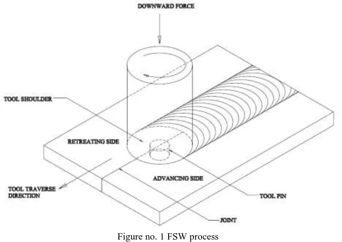
Friction Stir Welding is a hot-shear joining process in which a non-consumable, rotating tool plunges into a rigidly clamped workpiece and moves along the joint to be welded [3]. The cylindrical rotating tool used in FSW has a profiled threaded or unthreaded probe of length less than the weld depth, extruding from the tool shoulder. The operating principle of FSW process is presented in Fig 1.
Figure no. 1 FSW process
The FSW process is initiated by plunging of a rotating tool into the joint until the shoulder contacts the top surface of the workpiece. As the tool translates along the joint, heat is generated by rubbing action of tool shoulder against the workpiece (Figure3.2). Additional heat is generated by visco-plastic dissipation of mechanical energy at high strain rates due to interactions between tool and workpiece [5].
IJEDR1601116
International Journal of Engineering Development and Research (www.ijedr.org)672
forced to flow by the translation of the tool from the front to the back of the pin where it cools, consolidates and results in joint formation [6].FSW process requires a tool of harder material than the workpiece material being welded [2]. Previously, FSW was used for soft workpiece materials like aluminium alloys, lead, zinc, and magnesium. However, with the development of tools made from refractory material like tungsten and super abrasive materials like polycrystalline diamond (PCD) and polycrystalline cubic boron nitride (PCBN), FSW of high temperature materials was made possible [7]. As FSW process is a solid state process, it requires low heat input and it results in low distortion, no macro segregation, and a finely recrystallized microstructure. For these reasons, FSW has been investigated for wide range of materials including high melting temperature materials such as austenitic stainless steels [8].
The feasibility of FSW for high melting temperature materials have been studied and reported. Studies have shown the feasibility of FSW in several steels and have reported that the mechanical properties of friction stir welds are comparable to those of base material [8-11]. Further, continuing investigations suggest that the FSW of steel could have several commercial applications such as pipe fabrication, rail wagons, automotive parts and hot plate fabrication [2, 12].
II.LITERATURE REVIEW
Chao, Qi and Tang [21] formulated a boundary value problem for tool and workpiece in order to study the heat transfer in friction stir welding. They determined the frictional heat flux from the measured transient temperature fields obtained in the finite element analyses. In an attempt to predict the flow of material around the tool, Colegrove et al. [22] presented a finite element based thermal model of FSW. Their model included the backing plate and the tool. In their work, the heat input was fitted through iterative process for verification between the modeled and experimental values.
Vilaca et al. [25] developed an analytical thermal model for simulation of friction stir welding process. The model included simulation of the asymmetric heat field under the tool shoulder resulting from viscous and interfacial friction dissipation. The analytical model also considered the influence of hot and cold FSW conditions into the heat flow around the tool.
Zhu and Chao [28] presented three-dimensional nonlinear thermal and thermo-mechanical simulations using finite element analysis code –WELDSIM on 304L stainless steel friction stir welded plates. Initially, a heat transfer problem was formulated as a standard boundary value problem and was solved using the inverse analysis approach. The total heat input and heat transfer coefficient were estimated by fitting the measured temperature data with the analytical model. Later, the transient temperature outputs from the first stage were used to determine residual stresses in the welded plates using a three-dimensional elastic plastic thermo-mechanical model. Convection and radiation were assumed to be responsible for heat loss to the ambient on the surface. Their model provided good match between experimental and predicted results. They reported that the residual stress in the welds after fixture release decreased significantly as compared to those before fixture release. They also reported that about 50% of the total mechanical energy developed by FSW machine was utilized in raising the temperature of the workpiece.
Feng et al. [31] presented a more detailed thermal-metallurgical-mechanical model to study the microstructure changes and their effects on residual stress distribution in friction stir weld of Al6061-T6. In their approach, the first stage involved a transient nonlinear heat flow analysis to determine the temperature distribution. The frictional heating in the thin layer near the interface was treated as surface heat generation term, q, which was estimated by equation 1,
r
R
R
F
q
pin sh)
(
60
2
2 2
ForR
pin
r
R
sh Eq. 1Where 𝐹 is the downward force, 𝜔 is the rotational speed, 𝜂 is the process efficiency, is the interpretive coefficient of friction III. THERMO-MECHANICAL MODEL
The Finite Element Method (FEM) offers a way to solve complex continuum problems by subdividing it into a series of simple interrelated problems. FEM is most commonly used in numerical analysis for obtaining approximate solutions to wide variety of engineering problems. In the present study, a commercial general purpose finite element program ANSYS® 14.5 was used for numerical simulation of friction stir welding process.
3.1 THERMAL MODEL
The purpose of the thermal model is to calculate the transient temperature fields developed in the workpiece during friction stir welding. In the thermal analysis, the transient temperature field 𝑇 which is a function of time 𝑡 and the spatial coordinates (𝑥,y,z), is estimated by the three dimensional nonlinear heat transfer equation 2,
t
T
c
Q
z
T
y
T
x
T
k
int
2 2 2 2 2 2 Eq. 2Where k is the coefficient of thermal conductivity, Qint is the internal heat source rate, c is the mass-specific heat capacity, ρ is the density of materials.
3.2 ASSUMPTIONS
A number of assumptions have been made in developing the finite element thermal model, which include:
Workpiece material is isotropic and homogeneous.
No melting occurs during the welding process.
IJEDR1601116
International Journal of Engineering Development and Research (www.ijedr.org)673
Heat transfer from the workpiece to the clamp is negligible. 3.3 GEOMETRY
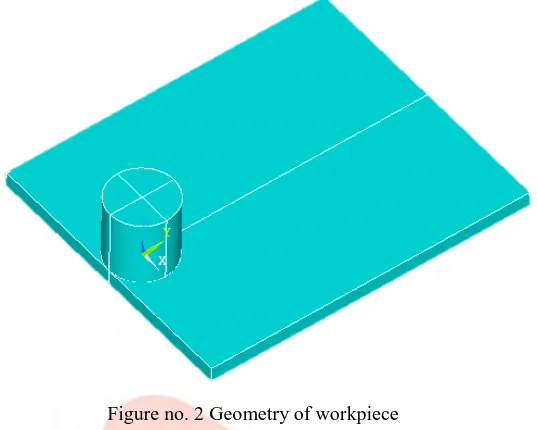
In the numerical model, only half of the welded plate is modeled as the weld line is the symmetric line. Symmetric condition is used to reduce the simulation time. The workpiece has dimensions of 0.0762 m x 0.03175 m x 0.00318 m as shown in Fig 2.
Figure no. 2 Geometry of workpiece 3.3 ELEMENT USED
In the present thermal analysis, the workpiece is meshed using a brick element called SOLID 226. This element has a three-dimension thermal conduction capability and can be used for a three- three-dimensional, steady-state or transient thermal analysis. The element is defined by eight nodes with temperature as single degree of freedom at each node and by the orthotropic material properties. Heat fluxes or convections (but not both) can be input as surface loads at the element.
3.4 MESH DEVELOPMENT
Three dimensional SOLID226 elements were used to mesh the sheets. The workpiece was divided into 22 parts along the length with spacing ratio 5, 44 parts along the width and 2 parts along the thickness direction. The mesh is comprised of a total number of 5214 elements and 7879 nodes.
3.5 BOUNDARY CONDITIONS
Boundary condition for FSW thermal model were specified as surface loads through ANSYScodes. Assumptions were made for various boundary conditions based on data collected from various published research papers [28, 30].
Convective and radiative heat losses to the ambient occurs across all free surfaces of the workpiece and conduction losses occur from the workpiece bottom surface to the backing plate. To consider convection and radiation on all workpiece surfaces except for the bottom, the heat loss qs is calculated by following equation 3,
4
0 4
0
T
T
T
T
q
s
Eq. 3where 𝑇 is absolute temperature of the workpiece, 𝑇0 is the ambient temperature, 𝛽 is the convection coefficient, 𝜀 is the emissivity of the plate surfaces, and 𝜍= 5.67 x 10⁻¹² 𝑊𝑐𝑚2℃ is the Stefan-Boltzmann constant. In the current model, a typical value of 𝛽 was taken to be 10 𝑊𝑚2℃ using an ambient temperature of 300 K and 𝜀 was taken to be 0.17 for 304L steel.
In order to account for the conductive heat loss through the bottom surface of weld plates, a high overall heat transfer coefficient has been assumed. This assumption is based on the previous studies [21, 28]. The heat loss was modeled approximately by using heat flux loss by convection 𝑞𝑏 given by following equation 4,
T
T
0
q
b
b
Eq.4Where 𝛽𝑏 is a fictitious convection coefficient.
Due to the complexity involved in estimating the contact condition between the sheet and the backing plate, the value of 𝛽𝑏 had to
be estimated by assuming different values through reverse analysis approach. In this study, the optimized value of 𝛽𝑏 was found
to be 100 𝑊/𝑐𝑚2℃.
IJEDR1601116
International Journal of Engineering Development and Research (www.ijedr.org)674
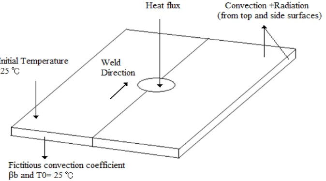
Figure no. 3 Schematic representation of boundary condition for thermal analysis.Heat is produced in the friction stir welding process due to the friction between the tool shoulder and workpiece interface and due to the plastic deformation of the weld metal near the pin. The heat generated by the plastic deformation of weld metal near the pin is of negligible magnitude and is difficult to quantify [21]. Hence, it was neglected in this study. Therefore in this model, the heat generated by friction between the workpiece and tool shoulder is the only source of heat generation.
The total heat input 𝑄 in watts for this model is calculated through Chao et al. [21] equation and is applied as a moving heat flux. The total heat input 𝑄 is given by following equation 5,
)
(
45
)
(
2 2i o
i i o o
r
r
r
r
r
r
F
Q
Eq. 5where 𝜔 is the tool rotational speed, 𝜇 is the frictional coefficient, 𝐹 is the downward force, 𝑟o and 𝑟i are the radii of the shoulder
and the nib of the pin tool.
The rate of heat input to the workpiece q(r) is assumed to be axis-symmetric and linearly distributed in the radial direction [21] and is calculated by equation 6,
3 3
2
3
i
o
r
r
Qr
r
q
Eq. 6In the present simulation, the heat flux q(r) obtained from the above equation is applied as surface load using tabular boundary condition. The movement of FSW tool is implemented by creating a local cylindrical coordinate system and calculating heat load at each node at each instantaneous time step.
The dimensions for tool and values for other parameters used in this study were obtained from Zhu and Chao [28] for correlation to the published research data. The tool shoulder diameter used in this study was 19.05 mm, while the pin diameter was assumed as zero. The assumption was made based on findings from Russell and Sheercliff that the heat generated at the pin of the tool is in the order of 2% of total heat and hence negligible. Fitted values of 𝑄 and 𝛽𝑏 were used in this study.
3.6 MECHANICAL MODEL
The following assumptions have been made in developing the structural model:
Deformation occurs symmetrically along the weld line, so only half of the workpiece is modeled.
The plate material is homogeneous.
The effect of creep is neglected because there is no cyclic thermal load involved.
IV.RESULTS
Finite element based model generated in previous chapter was use to find effect of input parameters on the output. The values of input parameters are increased by 10% and the results were plotted.
First analysis with 60 rpm and 2.71 mm/s tool velocity.
The objective of the project is to find Maximum Temperature and Frictional Heat generated during welding process. The main FSW process parameters that affect both the weld quality and the process efficiency are: (a) rotational and transverse velocities of the tool; (b) tool plunge depth; (c) tool tilt angle; and (d) tool design/material. Since, in general, higher temperatures are encountered in the case of higher rotational and lower transverse tool velocities, it is critical that a delicate balance between these two velocities is attained: i.e. when the temperatures are not high enough and the material has not been sufficiently softened, the weld zone may develop various flaws/ defects arising from low ductility of the material.
IJEDR1601116
International Journal of Engineering Development and Research (www.ijedr.org)675
Initially the Rotation of the tool is considered as 60 RPM and tool feed rate is 2.71 mm/sTotal Time steps = 29
There are total 3 steps in FSW process. Time require for each step is calculated Load step 1:
Tool is drilled into the workpiece.
To ensure that the necessary level of shoulder/workpiece contact pressure is attained and that the tool fully penetrates the weld, the tool plunge depth (defined as the depth of the lowest point of the shoulder below the surface of the welded plate) has to be set correctly. Typically, insufficient tool plunge depths result in low-quality welds (due to inadequate forging of the material at the rear of the tool), while excessive tool plunge depths lead to under-matching of the weld thickness compared to the base material thickness.
Depth of penetration is = thickness of plate/4000 Time required for step 1 = 1sec.
Load step 2:
Tool is rotated at given RPM, in this
case it
is 60RPM. Time Required for step 2: 6.5 sec.Load step 3:
Feed length= 60.96 mm Total time = 22.5 sec. Tool feed rate= 2.71 mm/s
Tool is translated along the weld line with 2.71 mm/s feed rate and the rotation of tool is 60 rpm. Lower the tool feed rate, better the quality of weld.
The analysis was carried out and the following results were plotted. (Rotation vs. max. temperature)
Graph 1 Max temperature vs. rotational speed
Graph 2 Frictional heat vs. rotational speed
1200
1250
1300
1350
1400
40
60
80
100
Max. Temperature
Max.
Temperature
0
500
1000
1500
0
20
40
60
80
100
Friction Heat
IJEDR1601116
International Journal of Engineering Development and Research (www.ijedr.org)676
Graph 3 Max temperature vs. velocity (rotational speed 60 rpm)Graph 4 Friction Heat vs. velocity (rotational speed 60 rpm)
Graph 5 Max temperature vs. velocity (rotational speed 66 rpm)
400
600
800
1000
1200
1400
1
2
3
4
5
Max. Temperature
Max.
Temperature
0
200
400
600
800
1000
1200
0
2
4
6
Friction Heat
Friction Heat
1050
1100
1150
1200
1250
1300
0
2
4
6
Max Temperature
Max
IJEDR1601116
International Journal of Engineering Development and Research (www.ijedr.org)677
Graph 6 Friction Heat vs. velocity (rotational speed 66 rpm)Graph 7 Max temperature vs. velocity (rotational speed 72 rpm)
Graph 8 Friction Heat vs. velocity (rotational speed 72 rpm)
800
820
840
860
880
0
5
Friction Heat
Friction
Heat
1140
1160
1180
1200
1220
1240
1260
1280
0
2
4
6
Max. Temperature
Max.
Temperature
880
885
890
895
0
2
4
6
Friction Heat
IJEDR1601116
International Journal of Engineering Development and Research (www.ijedr.org)678
Graph 9 Max temperature vs. velocity (rotational speed 78 rpm)Graph 10 Friction Heat vs. velocity (rotational speed 78 rpm)
Graph 11 Max temperature vs. velocity (rotational speed 84 rpm)
1263.7022
1263.7023
1263.7024
1263.7025
1263.7026
0
1
2
3
4
5
Maximum Temperature
Maximum
Temperature
965.50375
965.5038
965.50385
965.5039
965.50395
0
2
4
6
Friction Heat
Friction Heat
1365.2316
1365.2316
1365.2316
1365.2316
1365.2316
1365.2316
0
2
4
6
Max. Temperature
Max.
IJEDR1601116
International Journal of Engineering Development and Research (www.ijedr.org)679
Graph 12 Friction Heat vs. velocity (rotational speed 84 rpm)V. CONCLUSION
Non-linear Thermo-coupled analysis was use to find temperature and friction heat in welding process. It is observed that tool rotation speed and tool velocity plays an important role in friction stir welding process. Trends observe in the analysis are given below As the rotation speed of the tool increases, maximum temperature decrease because of increase in convection due to tool rotation. But at 84 rpm temperature again increases and it reaches the maximum value. This is the maximum temperature that we can get. Increased rotation speed also increases the friction heat developed between tool and the workpiece. At 60 rpm the effect of velocity is more. As the tool velocity increases it will reduce the Temperature of welding process. At higher tool rotation speed variation in maximum temperature due to tool velocity is negligible. The frictional heat is constant at higher tool rotation speed and is independent of tool velocity. At lower tool rotation speed, increase in tool velocity causes decrease in friction heat. For better weld we suggest higher tool rotation speed and lower tool velocity.
VI. REFERENCES
[1] Thomas, W.M., Nicholas, E.D., Needham, J.C., Murch, M.G., Temple Smith, P., and Dawes, C.J., Friction-stir butt welding, GB Patent No. 9125978.8, International patent application No. PCT/GB92/02203, (1991).
[2] http://steel.keytometals.com/default.aspx?ID=CheckArticle&NM
[3] Nandan, R., DebRoy, T., and Bhadeshia, H., Recent advances in friction-stir welding - Process, weldment structure and properties. Progress in Materials Science, 2008. 53(6): p. 980-1023.
[4] http://www.frictionstirlink.com/fslfswdescription.html.
[5] Lienert, T.J., Stellwag, W.L., Grimmett, B.B., and Warke, R.W., Friction stir welding studies on mild steel - Process results, microstructures, and mechanical properties are reported. Welding Journal, 2003. 82(1): p. 1S-9S.
[6] Zettler, R., Donath, T., dos Santos, J.F., Beckman, F., and Lohwasser, D., Validation of marker material flow in 4mm thick friction stir welded Al2024-T351 through computer micro tomography and dedicated metallographic techniques. Advanced Engineering Materials, 2006. 8(6): p. 487-490.
[7] Sorensen, C.D. and Nelson T.W., Friction Stir Welding of Ferrous and Nickel Alloys, in Friction stir welding and processing, Mahoney, M. W. and Mishra, R.S., Editors. 2007, ASM International: Materials Park, Ohio. p. 111-121.
[8] Park, S.H.C., Sato, Y.S., Kokawa, H., Okamoto, K., Hirano, S., and Inagaki, M., Microstructural characterization of stir zone containing residual ferrite in friction stir welded 304 austenitic stainless steel. Science and Technology of Welding and Joining, 2005. 10(5): p. 550-556.
[9] Park, S.H.C., Sato, Y.S., Kokawa, H., Okamoto, K., Hirano, S., and Inagaki, M., Rapid formation of the sigma phase in 304 stainless steel during friction stir welding. Scripta Materialia, 2003. 49(12): p. 1175-1180.
[10] Ozekcin, A., Jin, H.W., Koo, J.Y., Bangaru, N.V., Ayer, R., Vaughn, G., Steel, R., and Packer, S., A microstructural study of friction stir welded joints of carbon steels. International Journal of Offshore and Polar Engineering, 2004. 14(4): p.284-288.
[11] Reynolds, A.P., Tang, W., Gnaupel-herold, T., and Prask, H., Structure, properties, and residual stress of 304L stainless steel friction stir welds. Scripta Materialia, 2003. 48(9): p. 1289-1294.
[12] Posada, M., Nguyen, J.P., Forrest, D.R., DeLoach J.J., and DeNale, R., Friction stir welding advances joining technology, The AMPTIAC Quarterly, 2003. 7(3): p.13-20.
[13] Threadgill P.L., and Johnson R., The potential for friction stir welding in oil and gas applications. Proceedings of the Fourth International Offshore and Polar Engineering Conference, France, ISOPE, 2004. p.1-7.
[14] Defalco, J., and Steel, R., Friction stir process now welds steel pipe, Welding Journal, 2009. 88(5): p.44-48.
1009.4169
1009.417
1009.4171
1009.4172
1009.4173
1009.4174
1009.4175
2.6 2.8 3 3.2 3.4
Friction Heat
IJEDR1601116
International Journal of Engineering Development and Research (www.ijedr.org)680
[15] Bhat, B.N., Carter, R.W., Ding, R.J., Lawless, K.G., Nunes, A.V., Russell, C.K., and Shah, S.R., Friction stir weldingdevelopment at NASA- Marshall Space Flight Center, Friction Stir Welding and Processing, Jata, K.V., et al., Editor. 2001, TMS. P. 117-128.
[16] Benyounis, K.Y. and Olabi, A.G., Optimization of different welding processes using statistical and numerical approaches - A reference guide. Advances in Engineering Software, 2008. 39(6): p. 483-496.
[17] Feng, Z., Processes and mechanisms of welding residual stress and distortion. Woodhead Publishing in materials. 2005, Boca Raton, Fla.: CRC Press.
[18] TWI, http://www.twi.co.uk/content/ksrhl001.html.
[19] Kudryavtsev, Y.F., Residual stress, in Springer handbook of experimental solid mechanics, Sharpe, W.N., Editor. 2008, New York: Springer. p. 371-388.
[20] Gould, J.E. and Feng Z.L., Heat flow model for friction stir welding of aluminum alloys Journal of Materials Processing & Manufacturing Science, 1999. 7(2): p. 185-194.
[21] Chao, Y.J., Qi, X., and Tang, W., Heat transfer in friction stir welding - Experimental and numerical studies, Journal of Manufacturing Science and Engineering-Transactions of the ASME, 2003. 125(1): p. 138-145.
[22] Colegrove P, 3 Dimensional flow and thermal modeling of the Friction Stir Welding process, in: the Second FSW Symposium, Gothenburg, Sweden, 2000.
[23] Khandkar, M.Z.H., Khan, J.A., and Reynolds A.P., Prediction of temperature distribution and thermal history during friction stir welding: input torque based model, Science and Technology of Welding and Joining, 2003. 8(3): p. 165-174.
[24] Song, M. and Kovacevic, R., Heat transfer modelling for both workpiece and tool in the friction stir welding process: a coupled model. Proceedings of the Institution of Mechanical Engineers Part B-Journal of Engineering Manufacture, 2004. 218(1): p. 17-33.
[25] Vilaca, P., Quintino, L., and dos Santos, J.F., iSTIR - Analytical thermal model for friction stir welding. Journal of Materials Processing Technology, 2005. 169(3): p. 452-465.
[26] Chao, Y.J. and Qi, X.H., Thermal and thermo-mechanical modeling of friction stir welding of aluminium alloy 6061-T6. Journal of Materials Processing & Manufacturing Science, 1998. 7(2): p. 215-233.
[27] Chen, C.M. and Kovacevic, R., Finite element modeling of friction stir welding - thermal and thermo mechanical analysis. International Journal of Machine Tools & Manufacture, 2003. 43(13): p. 1319-1326
[28] Zhu, X.K. and Chao, Y.J., Numerical simulation of transient temperature and residual stresses in friction stir welding of 304L stainless steel, Journal of Materials Processing Technology, 2004. 146(2): p. 263-272.
[29] Soundararajan, V., Zekovic, S., and Kovacevic, R., Thermo-mechanical model with adaptive boundary conditions for friction stir welding of Al 6061. International Journal of Machine Tools & Manufacture, 2005. 45(14): p. 1577-1587.
[30] Khandkar, M.Z.H., Khan, J.A., Reynolds, A.P., and Sutton, M.A., Predicting residual thermal stresses in friction stir welded metals. Journal of Materials Processing Technology, 2006. 174(1-3): p. 195-203.
[31] Feng, Z., Wang, X.L., David, S.A., and Sklad, P.S., Modelling of residual stresses and property distributions in friction stir welds of aluminium alloy 6061-T6. Science and Technology of Welding and Joining, 2007. 12(4): p. 348-356