www.ijiset.com
Analysis Of Annular Plate By Using Numerical Method
Anand C Mattikalli1 and Dr. Rajashekar V. Kurahatti21
Faculty, Dept. of Mech Engg., Maratha Mandal. Engg. College, Belgaum, Karnataka
2Faculty, Dept. of Mechanical Engg., Basaveshwar Engineering College Bagalkot, Karnataka
Abstract
Stress analysis plays an important role in the design of machine or structural members. The stress analysis is mainly intended to estimate the load carrying capacity of the members. The present work deals with the study of static analysis of annular plate subjected to a uniformly distributed load. Annular plate with inner edge fixed and outer edge free is considered for the analysis. The finite element analysis tool Ansys has been successfully executed for the evaluation of maximum transverse deflection and stresses. The effect of aspect ratio and thickness on deflection and stresses is discussed.
Keywords: Annular plate, Static Analysis, FEM.
1. Introduction
Stress analysis plays an important role in the design of machine or structural members. The stress analysis is mainly intended to estimate the load carrying capacity of the members. The study of the behavior of annular plate is important, as several machine components, such as flywheels, clutch plates circular saw plates etc. can be considered as annular plates for the purpose of analysis. As structural elements, circular annular plates are extensively used in the construction of aircraft, ships, automobiles and other vehicles. The turbine disc is a well-known example for the industrial application of the annular plate. This study is fundamental for high-risk plants. Mechanics of materials and theory of elasticity approaches have been developed and successfully applied for the stress analysis of the members.
Mechanics of materials approach is simple but has limited applications due to the assumptions such as i) plane cross-sections before deformation remain plane after deformation and ii) geometry of the member does not contain any discontinuities. Theory of elasticity method, on the other hand, is free of these assumptions. It involves the derivation and integration of governing equations of a stress element of load carrying member. The exact closed form solution of these complex governing equations is obtainable only for cases of geometric, loading and material simplicity. While in case of members with complex materials, boundary, geometry and loading the elasticity solutions are impossible /prohibitively expensive. However, the solution of the exact elasticity equations of real life complex mechanics problem is attempted through
one of various approximate numerical solution techniques vogue in practice. For complex situations the finite element method based on the theory of elasticity is the versatile numerical technique solution to obtain an approximate solution. The accuracy of the results can be improved by modifying the degrees of freedom of the finite element mesh. In this work study of static analysis of annular disc is carried out.
2. Theoretical formulation
A static analysis calculates the effects of steady loading conditions on a structure, while ignoring inertia and damping effects, such as those caused by time-varying loads. A static analysis can, however, include steady inertia loads (such as gravity and rotational velocity), and time-varying loads that can be approximated as static equivalent loads (such as the static equivalent wind and seismic loads commonly defined in many building codes). Static analysis is used to determine the displacements, stresses, strains, and forces in structures or components caused by loads that do not induce significant inertia and damping effects. Steady loading and response conditions are assumed; that is, the loads and the structure's response are assumed to vary slowly with respect to time
The bending properties of plate depend greatly on its thickness as compared with other dimensions. If the load acting on a circular plate is symmetrically distributed about the axis perpendicular to the plate through its center, then at all points equally distant from the center of the plate the deflections will be the same. [12]
Consider a annular plate of outer radius ‘a’ and inner radius ‘b’ and thickness ‘h’ Let us consider the bending of a plate by the moments M1 and M2 uniformly distributed along the inner edge and outer boundaries respectively
M2 M1 M1 M2
b a
www.ijiset.com The differential equation for symmetrical bending of
laterally loaded annular plate is given by
(1)
Integrating twice
dw_ = C1r + C2 (2) dr 2 r
Integrating again we find the deflection
w = - C1r2 - C2 log r + C3 (3) 4 a
The constants of integration are now determined from conditions at the edges.
Several cases of practical importance with different boundary conditions can be studied. In all these cases the maximum stress is given by the formula [12]
σ max = k q a2 (4)
h2 or
σ max = k P (5)
h2
Depending on whether the applied load is uniformly distributed over the surface or concentrated along the edge. The numerical values of the factor k calculated for several values of ratio a/b and for poisson’s ratio γ = 0.3 are provided [12]
The maximum deflections for the various cases are given by the formulas of the type
Wmax = k1 q a4 (6)
E h3
Wmax = k1 P a 2
(7) E h3
3. Finite Element Model
The model of the annular plate is created using finite element tool Ansys 14 version. The entire annular plate is modeled as a surface model. The annular plate is modeled by using SHELL 63 elastic shell four nodded quadrilateral element with six degrees of freedom at each node. The model is meshed with quadrilateral and free meshing. The details of meshed model is as shown in the Figure.2
Fig.2 Meshed model
3.1 Boundary Condition
The boundary conditions applied to the model are the inner edge of the annular plate is clamped i.e. all degrees of freedom are constrained and outer edge is free.
4. Material Properties
An isotropic material Mild steel is used as the material for the annular plate and its analysis is carried out. The properties of the material are as follows
Young’s Modulus: 210000 N/mm2 Poisson’s ratio: 0.3
Weight Density: 7850 kg/m3
5. Results
5.1 Effect Of Thickness On The Deflection And
Stresses Developed In The Annular Plate.
Annular plate with inner edge clamped and outer
edge free is considered for the analysis. Inside and
outside diameters of the annular plate are kept
constant throughout the analysis. The plate is
subjected to a constant uniformly distributed load.
The thickness of the plate is varied to determine the
effect of thickness on deflection and stresses
developed in annular plate. The analysis is carried
out using finite element analysis tool Ansys and
results are compared with analytically calculated
values.
The Table 1 shows results of the analysis, the effect
of thickness on the deflection of annular plate and
comparison of results obtained from Ansys and
analytical method.
www.ijiset.com
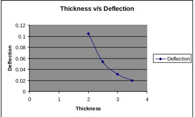
Table.1 Effect of thickness on deflection
Thickness
of plate
Deflection (mm)
%
Error FEM
result Analytical
2.0 0.104913 0.1049107 0.002
2.5 0.053715 0.0537142 0.0014
3.0 0.031085 0.0310846 0.0012
3.5 0.019576 0.0195751 0.004
The results obtained from the finite element method
co-relate with the analytical method.
Thickness v/s Deflection
0 0.02 0.04 0.06 0.08 0.1 0.12
0 1 2 3 4
Thickness
D
e
fl
e
c
ti
o
n
Deflection
Fig.3. Graph showing the effect of thickness on deflection
The Table 2 shows the effect of thickness on the Stresses developed in annular plate and comparison of results obtained from Ansys and analytical method.
. Figure 4 shows plot of Stresses developed v/s thickness of annular plate. Figure 6 shows the effect of thickness on deflection and stresses developed in Annular plate.
Table.2 Effect of thickness on stresses
Thickness
of plate
Stress (N/mm2)
%
Error FEM
result Analytical
2.0 114.886 115.3125 0.37
2.5 73.527 73.8 0.37
3.0 51.06 51.25 0.37
3.5 37.514 37.653 0.37
The results obtained from the finite element method co-relate with the analytical method.
Stress
0 20 40 60 80 100 120 140
0 1 2 3 4
Thickness
S
tr
e
ss
Stress
Fig.4 Graph showing the effect of thickness on stress
(a)Thickness 2mm (b)Thickness 2.5mm
(c)Thickness 3mm (d)Thickness 4mm
Fig. 5 showing the effect of thickness on deflection and stresses developed in Annular plate
5.2 Effect Of Aspect Ratio On The Deflection And
Stresses Developed In The Annular Plate
Annular plate with inner edge clamped and outer edge free is considered for the analysis. Inside diameters of the annular plate are kept constant throughout the analysis and outside diameter is varied to get different aspect ratios. The plate is subjected to a constant uniformly distributed load and the thickness of the plate is kept constant for all the cases. The analysis is carried out using finite element analysis tool Ansys and results are compared with analytically calculated values
The Table 3 shows results of the analysis, the effect of aspect ratio on the deflection of annular plate and comparison of results obtained from Ansys and analytical method.
www.ijiset.com
Table.3 Effect of Aspect ratio on deflection
Aspect Ratio
Deflection (mm) %
Error FEM
result
Analytical
1.5 0.278x10⁻⁴ .2757x10-4 0.008
2.0 0.449x10⁻³ 0.4467x10⁻³ 0.51
3.0 0.006982 0.007063 1.146
4.0 0.034159 0.034133 0.076
5.0 0.104913 0.1049107 0.002
The results obtained from the finite element method co-relate with the analytical method
Aspect ratio v/sDeflection
-0.02000000 0.00000000 0.02000000 0.04000000 0.06000000 0.08000000 0.10000000 0.12000000
0 1 2 3 4 5 6
Aspect ratio
D
e
fl
e
c
ti
o
n
Deflection
Fig .6 Graph showing the effect of Aspect ratio on deflection
The Table 4 shows results of the analysis, the effect of aspect ratio on the stresses developed in the annular plate and comparison of results obtained from Ansys and analytical method
Table.4 Effect of Aspect ratio on stress
Aspect
Ratio
Stress (N/mm2) %
Error FEM
result
Analytical
1.5 1.135 1.1531 1.56
2.0 5.028 5.2 3.3
3.0 23.799 24.1875 1.6
4.0 59.715 59.8 0.14
5.0 114.886 115.3125 0.37
Figure.7 shows plot of Stress v/s Aspect ratio. Figure.8 shows the effect of aspect ratio on deflection and stresses developed in annular plate
Aspect ratio v/s stress
0 20 40 60 80 100 120 140
0 1 2 3 4 5 6
Aspect ratio
S
tr
e
ss
Stress
Fig.7 Graph showing the effect of Aspect ratio on stress
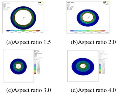
(a)Aspect ratio 1.5 (b)Aspect ratio 2.0
(c)Aspect ratio 3.0 (d)Aspect ratio 4.0
Fig. 8 showing the effect of thickness an deflection and stresses developed in Annular plate
6. Discussion on the Results
Static analysis is carried out to determine the deflection and stresses developed in the plate. The annular plate is subjected to uniformly distributed load. The effect of thickness on deflection and stresses developed in the annular plate is studied by keeping the aspect ratio and load acting on the annular plate constant. It can be observed from the Fig.3 and Fig.4 that the deflection of the plate and the stresses developed decreases with the increase in thickness. The deflection of the plate is decreased with increase in thickness due to increase in stiffness of the plate.
www.ijiset.com the deflection and stresses increase with increase in the
span of the annular plate. The results obtained from the finite element method co-relate with the analytical method.
7. Conclusion
It can be observed that both the deflection and the stresses developed in the plate decrease with increases in the thickness of the plate. Both the deflection and stresses increase with increase in the span of the annular plate i.e. with increase with increase in ratio of outer radius to inner radius of the plate. There is considerable increase in deflection for plates with higher aspect ratios. The results obtained from the finite element method co-relate with the analytical method.
It is possible to study the static response of the machine and structural elements of complicated shapes with desired accuracy and quickness and it is possible to generate useful design data for the static response of plate with various boundary conditions and loadings.
References:
[1] S. Timoshenko and S. Woinowsky-Krieger, “Theory of Plates and shells” Second edition, McGraw Hill International Editions, 1959.
[2] Singiresu S. Rao, “Mechanical Vibrations” Fourth edition, Pearson’s Education, 2004.
[3] V. P. Singh, “Mechanical Vibrations”, Dhanpat Rai & Co., 2001.
[4] S. Graham Kelly, “Fundamentals of Mechanical Vibrations” Second edition, McGraw Hill International Editions, 20000.
[5] T. R. Chandrupatla and A. D. Belegundu, “Finite Elements in Engineering”, Third edition, Prentice-Hall Inc, 2002.
[6] J. N. Reddy, “Finite Element Method” Second edition, McGraw Hill International Editions, 1993.
[7] S. Graham Kelly, “Mechanical Vibrations”, Tata McGraw Hill International Editions, 1996.
[8] Rudolph Szilard, “Theory & Analysis of plates classical and numerical Methods”, Prentice-Hall Inc, 1974.
[9] S. Timoshenko, “Strength of Materials” part 2, First edition, CBS Publishers and Distributors, 1986.
[10] Zienkiewicz O. C., “The Finite Element Methods”, Mc Graw Hill, Ed. 1979.
[11] ANSYS Release 14.0 Documentation
[12] S. Timoshenko and S. Woinowsky-Krieger, “Theory of Plates and shells” Second edition, McGraw Hill International Editions, 1959
[13] S.S. Bhavikatti, “Finite Element Analysis”, New Age International Publishers,2005
[14] Syed Noh, Mostafa Abdalla, Waleed Fekry Faris “A Study of Annular Plate Buckling Problem with Tension Loaded at Inner Edge”, ANUL XVII, NR. 1, 2010, ISSN 1453 – 7397.
[15] Hamed Vahdati Zadeh and Masoud Tahani, “Analytical Bending Analysis Of A Circular Sandwich Plate Under Distributed Load ”, International Journal of Recent Advances in Mechanical Engineering (IJMECH) Vol.6, No.1, February 2017.
[16] P. S. Gujar, K. B. LadhaneBending, “Analysis of Simply Supported and Clamped Circular Plate”, SSRG International Journal of Civil Engineering (SSRG-IJCE) Volume 2 Issue 5–May 2015.
[17] R.Art Babu , U.S.Ramakanth, Ch.Venkata Anvesh, “Compressive And Torsional Buckling Analysis Of Circular And Annular Plate With Different Materials”, Energy Procedia 00 (2016) 000–000
[18] Jaan Lellep, Julia Polikarpus, “Elastic plastic bending of stepped annular plates”, Applications of Mathematics and Computer Engineering
[19] L. B. Raut, Ramsagar A. Kalyankar, “Experimental Analysis Of Circular Disc With Diametral Slots, International Journal of Mechanical Engineering and Technology (IJMET), ISSN 0976 – 6340(Print), ISSN 0976 – 6359(Online), Volume 6, Issue 2, February (2015)
[20] Fatemeh Farhatnia , Arash Golshah, “Investigation on Buckling of Orthotropic Circular and Annular Plates of Continuously Variable Thickness by Optimized Ritz Method”, Int. J. Simul. Multidisci. Des. Optim. 4, 127-133 (2010)
[21] R. S. Srinivasan and L. S. Ramachandra, “Large Deflection Analysis Of Bimodulus