Renewable Energy Based Interleaved Boost Converter
Pradeepakumara V1 , Nagabhushan patil2 PG Scholar 1, Professor2
Department of EEE
Poojya Doddappa Appa College of Engineering, Kalaburagi, Karnataka, India.
Abstract
Nowadays, there is a demand to increase the power generation capacity because of steadily rising electrical energy consumption. In order to achieve this, renewable energy sources are the best option. Among all the renewable energy sources, solar power generation system tops the list. For increasing the output of these sources we need a suitable boost converter. Interleaved boost converter (IBC) is one of such converter which consists of several identical boost converters connected in parallel and controlled by interleaved method, which has same switching frequency and phase shift. The advantages of using IBC over conventional boost converter are increased efficiency, improved reliability, reduced current peak value and these converter cells have good current sharing characteristics. The proposed method provides the increased output voltage along with efficiency. Here, in this work we have also shown the application of IBC in running BLDC motor. To detect the position of BLDC motor hall sensors are used. The proposed strategies have been verified with the help of MATLAB/SIMULINK along with the hardware implementation.
Keywords—interleaved boost converter, Solar energy, current sharing, BLDC motor, hall sensor.
1. Introduction
The global electrical energy consumption is steadily rising and consequently there is a demand to increase the power generation capacity without harming the environment. Renewable energy sources are the best options due to their effective operation and also they do not pollute the environment, the way burning the fossil fuels does. Solar power generation system tops the list of renewable energy sources, as the other sources such as wind, hydro, tidal sources even when taken them together will not meet the demand as the solar energy source does.
But for our application we need more amount of voltage than what we are getting from solar cells, to achieve this, we need to boost up the output voltage. For this purpose we need to use Interleaved method to improve power converter performance interms of efficiency. The Interleaved consists of several identical boost converters connected in parallel.
As the output current is divided by the number of phases, the current stress on each MOSFET’s is reduced. Each mosfet is switched at the same frequency but at a phase difference of 180 degrees. The desired output voltage for a given input voltage is depends on the duty ratio. For example, if the input
have to keep the duty cycle at 0.5. Since, we are using two similar inductors in the circuit this will leads to equal sharing of the input current.
Here, in this proposed method two phase IBC is chosen since the ripple content reduces with increase in number of phases. But, if the number of phases increased further without much decrease in ripple content, the complexity of circuit increases very much, there by increasing the cost of implementation. Hence, as a tradeoff between the ripple content and the cost complexity, number of phases are chosen as two.
2. Operation of IBC
Since as we are using two phases the converter is driven 180 degrees out of phase, this is because the phase shift is given by 360/n. where n stands for number of phases. Hence its clear that the phase shift is depends the number of phases used.
When gate pulse is given to the first for time t1, the current across the inductor rises and energy is stored in the inductor. When the switch s1 in the first phase turned off, the energy stored is transferred to the load through the output diode SD1. The inductor and the capacitor serve as voltage sources to extend the voltage and to reduce the voltage stress on the switch. The increasing current rate across the output diode is controlled by inductances the phases. Now the gate pulse is given to the second phase during the period t1 to t2 when the switch in the first phase is turned OFF. When the switch in the second phase turned ON, the inductor charges for the same time and transfers energy to the load in the similar way as in the first phase. Therefore, two phases feed the load continuously. Thus the proposed converter operates in continuous conduction mode.
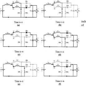
Fig. 2 Operation state and current paths of the converter
Referring to the equivalent circuits for the different switching states shown in Fig.3.3 and the waveforms in Fig. 4, the operation of the converter can be explained as follows:
1) State a [fig 3.2(a)] :
At time t₀, SW₁ is closed. The current in the inductor L₁’
starts to rise while L₂’ continues to discharge. The rate of change of iL₂’ is approximately given by
diL₁ 𝑑𝑡 =
−𝑉₀ 𝐿₁′+ 𝐿₂′
2) State b [fig 3.2(b)] :
At time t₁, iL₂ falls to zero, iL₁continues to rise and the rate of change of iL₁ is given by
diL₁ 𝑑𝑡 =
𝑉𝑖 𝐿₁ Where L₁′ = L₁ + Lm 3) State c [fig 3.2(c)] :
At time t₂, SW₁ is opened. The energy stored in the inductor L₁ is transferred to the load via the boost rectifier SD₁. The rate of change of iL₁, is
diL₁ 𝑑𝑡 =
−(𝑉₀ − 𝑉𝑖) 𝐿₁
4) State d [fig 3.2(d)] :
The switch SW₂ is closed at time t3. The current in inductor L₂′ starts to rise, L₁′ continues to discharge. The rate of change of iL₁ is approximately given by
diL₁ 𝑑𝑡 =
−𝑉₀ 𝐿₁′+ 𝐿₂′
5) State e [fig 3.2(e)] :
At time t4, the inductor current iL₂rises at the rate of diL₂
𝑑𝑡 = −𝑉₀
𝐿₂
Where L₂ = L₂′ + Lm 6) State f [fig 3.2(f)] :
At time t5, SW₂ is opened. L₂′ discharges through the output circuit. The rate of change of iL₂is
diL₂ 𝑑𝑡 =
−(𝑉₀ − 𝑉𝑖) 𝐿₂
2.1 Design of IBC
The design process involves the proper selection of inductor, duty cycle, resistance and capacitor values.
1) Duty cycle 𝑉0 𝑉𝑖𝑛 =
1 1−𝐷
D = 1 - 𝑉𝑖𝑛 𝑉₀
D = 1 - 60 120 = 0.5
2) Resistance
RLoad = 𝑉₀ 𝐼₀
RLoad = 120
3) Capacitor
C = 𝐷∗𝑉0∗𝑇 𝑅∗ ∆ 𝑉0
Take fs = 1 KHz T = 1
𝑓𝑠= 1
1 𝐾 = 1 * 10 −3 sec
∆ 𝑉0 ≃ 0.5% = voltage ripple
C = 0.5 ∗120 ∗1∗ 10 −3
10∗05 = 120 * 10 −3 F
4) Inductor
L = 𝑉𝑖𝑛 ∗𝐷 𝑚 ∗𝑛∗𝑓∗ ∆ 𝐼
m = number of switches per channel n = number of channels
∆ 𝐼 = input current ripple ≃ 0.5 %
L = 60 ∗ 0.5
1∗2∗100 ∗0.5 = 30 mH
Both the inductors used here are of similar rating that is both are having 30 mH of inductance. Since, we are using two similar inductors this will help us in sharing the input currents equally. And also, the inductor peak current rating is also reduced, there by reducing the inductor rating and cost of inductor.
2.2 Advantages of IBC
1) IBC has increased efficiency as compared to that of conventional boost converters.
2) IBC has low input current ripple.
3) It also has fast transient response and improved reliability. 4) Steady-state voltage ripples at the output side of capacitors of IBC are reduced.
5) By using IBC we can efficiently utilize the PV cell output. 6) By using TWO phases IBC we can reduce the cost complexity.
7) This method is Environmental friendly.
3. Brushless dc (BLDC) motor and its working
A BLDC motor is also known as electronically commutated motor. These motors are powered by a DC electric source via an integrated inverter or a switching power supply, which produces an AC electric signal to drive the motor. The difference between the conventional DC motor and a BLDC motor is that, the commutator is electronic, and the field is rotating with armature in static condition. A typical BLDC motor has permanent magnets which rotate around a fixed armature, eliminating the problems associated with connecting current to the moving armature. Feedback usually requires an attached Hall sensor or a rotary encoder, which helps in detecting the position of rotor. The stator windings work in conjunction with permanent magnets on the rotor to generate a nearly uniform flux density in the air gap. This permits the stator coils to be driven by a constant DC voltage (hence the name brushless DC), which simply switches from one stator coil to the next to generate an AC voltage waveform with a trapezoidal shape.
3.1
Working
Stator windings of a BLDC motor are connected to a control circuit. The control circuit energizes proper winding at proper time, in a pattern which rotates around the stator. The rotor magnet tries to align with the energized electromagnet of the stator, and as soon as it aligns, the next electromagnet is energized and this process will continue. This will make the rotor to run continuously.
3.2 BLDC
motor advantages
Following are some of the advantages of BLDC motor: High Speed Operation – A BLDC motor can operate at
speeds above 10,000 rpm under loaded and unloaded conditions.
Responsiveness and Quick Acceleration – Inner rotor Brushless DC motors have low rotor inertia, allowing them to accelerate, decelerate, and reverse direction quickly.
High Power Density – BLDC motors have the highest running torque per cubic inch of any DC motor.
High Reliability – BLDC motors do not have brushes, meaning they are more reliable and have life expectancies of over 10,000 hours. This results in fewer instances of replacement or repair.
Comparing with brushed DC motor, BLDC motor has increased efficiency, longer life time, no sparking and less noise, more torque per weight.
Due to the nature of solar energy, two components are required to have a functional solar energy generator. These two components are a collector and a storage unit. The collector simply collects the radiation that falls on it and converts a fraction of it to other forms of energy (either electricity and heat or heat alone). The storage unit is required because of the non-constant nature of solar energy; at certain times only a very small amount of radiation will be received. Or else we need to have a backup power supply. Here in my work, instead of having storage unit, I am going to use a back up power supply.
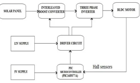
Fig. 3 Block diagram of the proposed system
The output of the solar panel is given to the interleaved boost converter (IBC), which will boost the output voltage of the solar panel. This IBC consists of two switches and the control circuit of the BLDC motor which is a three phase inverter consists of 6 switches, the driver signals for these switches are taken from a driver circuit, which intern is controlled by the PIC16F877A microcontroller. The control circuit energizes proper winding at proper time, in a pattern which rotates around the stator of the BLDC motor. Feedback from the BLDC motor is achieved by using hall sensor, which is connected to the PIC16F877A microcontroller. Hall sensors will work on the hall-effect principle, that when a current-carrying conductor is exposed to the magnetic field, charge carriers experience a force based on the voltage developed across the two sides of the conductor. If the direction of the magnetic field is reversed, the voltage developed will reverse as well. For hall-effect sensors used in BLDC motors, whenever rotor magnetic poles (N or S) pass near the hall sensor, they generate a HIGH or LOW level signal, which can be used to determine the position of the shaft. According to these signals the microcontroller will control the driver circuit, which intern will control the operation of the BLDC motor. The driver circuit here works as an amplifier. The output pulse voltage from PIC16F877A is of only 5V, driver circuit will amplify this voltage pulse to 12V, and then it will send those switching pulses to switches used in the circuit. Here, in my work I am also controlling the speed of the BLDC motor, by
This will help us to run the motor above or below the rated speed.
4. Simulation results and discussion
According to the design, the circuit diagram of simple IBC and simple Boost converters along with their application is plotted using MATLAB/SIMULINK and their respective voltage and corresponding speed of the motor are noted and compared.
The figs 4 and 5 shows that the output voltage of IBC is 118 V where as that of conventional boost converter is only 106 V. This clearly shows us that the efficiency of IBC is more than that of the boost converter.
Fig. 4 output voltage waveform of boost converter
Fig. 5 output voltage waveform IBC
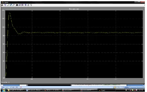
can get nearly 1200 rpm of motor speed. This will help in increasing the motor efficiency.
Fig. 6 motor speed waveform with boost converter
Fig. 7 motor speed waveform with IBC
The below table is prepared for output power and efficiency for different input power using simulation.
Table 1) output power and efficiency for different input power
Fig. 8 graph of obtained results
This graph clearly shows that, the efficiency of the proposed converter increases with increase in output power.
5. Experimental setup and its results
Fig. 9 Experimental set up of hardware
The above figure represents the experimental setup of interleaved boost converter in running a BLDC motor. The input supply from the solar panel is given to the IBC and the output of IBC is used for running the BLDC motor. This model consists of totally 8 switches 2 are of IBC’s and the rest 6 are of inverter. The driving signals for these switches are given from the pic microcontroller through the driver circuit. The position of the rotor of BLDC motor is sensed by using hall sensors, and this feedback is given to the PIC16F877A microcontroller.
Table 2) Input power, output power and efficiency
92 93 94 95 96 97 98 99
-5000 0 5000 10000 15000 20000
%
e
fficie
n
cy
output power
INPUT SIDE OUTPUT SIDE % η
V (volt)
I (amp)
P (watt)
V (volt)
I (amp)
P (watt)
% η
5 1.8 9 9.2 0.91 8.372 93.02
12 4.6 55.2 22.9 2.29 52.44 95
60 24 1440 117.9 11.8 1391.22 96.6
120 48 5760 237 23.68 5612.9 97.43
200 80 16000 395 39.5 15602.5 97.8
Input voltag e(V)
Input curren t(A)
Input power (W)
Output voltage (A)
Output current (V)
Output power (A)
Efficie ncy (%)
6. Conclusion
This dissertation work shows the design and implementation of interleaved boost converter. Comparison between conventional boost converters with the proposed IBC along with their application in running a BLDC motor with the motor speed variation is shown by using MATLAB/SIMULINK. From the obtained results we can conclude that, the IBC has higher boosting capacity, reduced inductor peak current and increased efficiency compared to that of conventional boost converters. The graph of efficiency versus output power is plotted and this graph clearly shows that, the efficiency of the proposed converter increases with increase in output power. And also it is clear that the selection of converter also plays an important role in efficient utilization of the renewable source output. The results also shows us that, the output of IBC is higher with less ripple content than that of conventional boost converter which helps in increasing the speed and efficiency of BLDC motor.
REFERENCES
[1] J.S.Anu Rahavi,T.Kanagapriya,Dr.R.Seyezhai “Design and Analysis of Interleaved Boost Converter for Renewable Energy Source” in Proc, International Conference on
computing, Electrical and Electronics
Technologies,2012,pp.447-451.
[2] R.Ramaprabha,K.Bhargav Raj and V.D.Logeshwaran “Analysis of Photovoltaioc System fed Interleaved Boost Converter” in Proc,International Conference on computing, Electrical and Electronics Technologies,2012,pp.399-403. [3] Nasir Coruh,Satilmis Urgun,Tarik Erfidan,Semra Ozturk “A Simple and Efficient implementation of Interleaved Boost Converter” in 6th IEEE Conference on Industrial Electronics
and Applications,2011,pp.2364-2368.
[4] Po-Wa Lee,Yim-Shu Lee,David K.W.Cheng,Xiu-Cheng Liu “Steady-State analysis of an Interleaved Boost Converter with coupled inductors” in Proc, IEEE Transaction on Industrial Electronics, vol 47,No 4,August 2000,pp.787-795. [5] Chandra sekhar, G.Yognjalu reddy and sanjay Lakshmi Narayan “Design simulation and validation of solar inverter with two phase interleaved boost converter” International conference on power and advanced control engineering 2015,pp.7-11.
[6] M. Shanmuga priya, R.Balasubramanium “Analysis of multideevice interleaved boost converter for high power application” International Conference on circuit, power and computing technologies, 2014,pp.320-327.
Author’s profile :
Pradeepakumara V, PG Scholar Dept of EEE, PoojyaDoddappa college of engineering, kalburgi, Karnataka, India, [email protected]