An
Open Application Interface (OAI)
User and Installation Guide
NEC America, Inc.
NEC America reserves the right to change the specifications, functions, or features in this document at any time without notice. NEC America has prepared this document for use by its employees and customers. The information contained herein is the property of NEC America and shall not be reproduced without prior written approval from NEC America.
Copyright 1999
TABLE OF CONTENTS
Page
Chapter 1 - OPERATING PROCEDURES . . . 1
Introduction . . . 1
Procedures . . . 2
Start Second Party Alert . . . 2
Caller Identification . . . 2
Browse List of Callers . . . 3
Signal an Internal Caller. . . 4
Return Call to an Internal Caller. . . 5
Return Call to an Outside Caller . . . 6
Quit Second Party Alert . . . 6
Display Formats . . . 7
Internal Call Display Format. . . 7
External Call Display Format . . . 8
CCIS Call Display Format . . . 9
Function Key Assignments . . . 10
Chapter 2 - INSTALLATION AND CONFIGURATION. . . 11
Installation. . . 11
Software Installation. . . 13
Configuration. . . 22
Access System Administration Menu. . . 22
Change Facility Number . . . 22
Configure Application . . . 23
Chapter 3 - DATABASE REQUIREMENTS . . . 29
Instructions . . . 29
Name Display Database Information . . . 30
Phone Line Database Information . . . 31
Tenant Number Database Information. . . 32
Chapter 4 - MAT ASSIGNMENTS . . . 33
AIPT Command: (Assignment of Interface I/O Port Data in IP) . . . 34
ASYD Command: Assignment of System Data . . . 34
ASDT Command: Assignment of Station Data . . . 34
AOKC Command: (Assignment of OAI Key Codes) . . . 35
AKYD Command: (Assignment of Dterm Function Key) . . . 35
LIST OF FIGURES
Figure Title Page
1-1 Dterm Telephone Set . . . 2
1-2 Caller ID SPA Display . . . 2
1-3 Example of SPA Display . . . 3
1-4 Signal Internal Caller . . . 4
1-5 Placing an Internal Call . . . 5
1-6 Placing an Outside Call . . . 6
1-7 Dterm Telephone Set . . . 6
1-8 Dterm Display (Internal Call) . . . 7
1-9 Dterm Display (External Call) . . . 8
1-10 Dterm Display (CCIS Call). . . 9
1-11 Dterm Keypad Layout . . . 10
2-1 Active Application Error . . . 13
2-2 Password Screen . . . 13
2-3 Previous Version Detected . . . 14
2-4 Delete Previous Version . . . 14
2-5 Saved Previous Version Confirmation Message . . . 14
2-6 Database Exists . . . 15
2-7 Verify MSF Op-code . . . 15
2-8 Confirm OAI Key Code . . . 16
2-9 Verify Chime Tone. . . 16
2-10 Secondary Line Chime Flag . . . 17
2-11 Local Area Code . . . 17
2-12 Verify Trunk Access Prefix . . . 17
2-13 Local Call Method . . . 18
2-14 SPA Auto-Config (New Config) . . . 19
2-15 SPA Auto-Config Complete (New Config). . . 19
2-16 SPA Auto-Config (Existing Config) . . . 20
2-17 SPA Auto-Config Complete (Existing Config) . . . 20
2-18 Database Template Installation. . . 21
4-1 OAI Function Key Assignment . . . 33
Chapter 1
OPERATING PROCEDURES
Introduction
Second Party Alert (SPA) allows you to identify the person who is calling on another line without interrupting the current call. If you receive a call on a secondary line while you are on the phone, you can press a function key that enables SPA to identify the caller on the Dterm Liquid Crystal Display (LCD) panel. Information can be displayed on more than one caller. Each time you press the function key, SPA displays the name and extension of the next caller. The calls are displayed in the order in which they are received.
You can also use SPA to send a signal to an internal caller that you are on another line and cannot answer. SPA then enables you to return the unanswered call later with the press of a key.
Note: SPA can work in conjunction with the OAI Name Display application which displays names and extensions on the Dterm. If Name Display is installed, SPA
Procedures
The following procedures outline the steps for using Second Party Alert (SPA).
Start Second Party
Alert
You can start SPA at any time, even if you are already speaking on a line, by pressing the Dterm key assigned to SPA. If you are not sure which key to use, see your system administrator.
Figure 1-1 Dterm Telephone Set
Caller
Identification
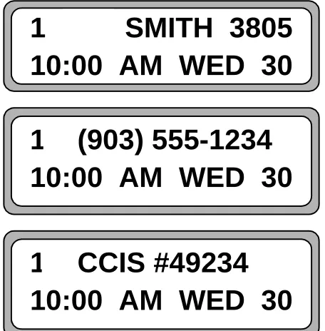
If you are speaking to someone, and receive a internal or external call, SPA will display a message on the Dterm. The display has the format as specified in section Display Format on page 7 with a blank call signal. Some typical examples are:
Figure 1-2 Caller ID SPA Display
1 2 3 4 5 6 7 8 9 * 0 #
To start SPA, press the assigned
Dterm key at any time.
1 SMITH 3805
10:00 AM WED 30
1 (903)
555-1234
10:00 AM WED 30
1 CCIS
#49234
Browse List of
Callers
When you are using SPA, information about incoming and outgoing calls displays on the Dterm LCD. Figure 1-3 illustrates a typical SPA display:
Figure 1-3 Example of SPA Display
In the illustration above, a person named Smith is calling on line 1 from extension 3805. For more information about the items shown on the LCD, see “Display Formats” on page 7.
To browse the list of callers:
1. Make sure SPA is active. (For more information on activating SPA, see “Start Second Party Alert” on page 2.)
You will see one of the following types of information on the Dterm display: • <Line number> <Name> <Extension Number> - The line number of the
call followed by the caller’s name and extension, as in Figure 1-3.
• Outgoing - Indicates the call is an outgoing call placed from your phone.
• Unlisted - Information for the internal caller is not available.
• Outside - Indicates that the incoming call was placed from outside the PBX. (If ANI data is available, the area code, prefix, and suffix are displayed. See
Figure 1-9 on page 8 for an example of an outside call with available ANI data.)
• No Calls - Indicates that no calls have been received or placed.
2. To view information for the next call on the display, press the assigned Dterm key (6 or 8).
3. To view information for the previous call on the display, press the assigned Dterm
key (2 or 4).
Signal an Internal
Caller
If you are currently speaking with someone and receive an internal call, you can use SPA to identify who is calling. You can also signal the caller to acknowledge the call and indicate you are on another line.
1. When you receive the internal call, you can see the caller’s name and phone extension on your telephone display.
For more information on the display, refer to “Internal Call Display Format” on page 7.
2. To acknowledge the call and signal the caller that you are busy or on another line, press the Dterm key assigned for signaling a caller on a subline (1 or #). The party hears a chiming sound. This sound indicates to the caller that you acknowledge the call but cannot answer right now.
When you browse the list of callers, the parties you signaled with the chime display with an asterisk (*) before their names as in Figure 1-4. For more information on how to browse a list, see “Browse List of Callers” on page 3.
Figure 1-4 Signal Internal Caller
Note: The Dterm display can only show six lines of information at one time. If you are on the phone, information for up to five calls can display. If you receive more than five calls, previous calls are overwritten on the display.
Return Call to an
Internal Caller
To return an internal call:
1. Browse the list of callers to find the call you want to return. For more information on browsing calls and information displayed on the LCD, see
“Browse List of Callers” on page 3 and “Internal Call Display Format” on page 7.
2. When information for the call you want to return is displayed, press the Dterm
key assigned for returning a call (1 or #).
3. “Calling” or one of the following messages appears:
• “Phone Busy” — Indicates that the phone you are calling is busy.
• “Bad Number” — Indicates that the number is invalid.
• “Call Failed” — Indicates that an error occurred when the call was placed.
• “DB Error” — Indicates that a database error occured.
Figure 1-5 Placing an Internal Call
4. When you browse the list of callers after returning a call (see “Browse List of Callers” on page 3), one of the following symbols appears before the party’s name and number:
• ->
Displays when the number is called and no answer is received
• <-
Displays when the number is called and the party answers (internal calls only)
Return Call to an
Outside Caller
To return an outside call:
1. Browse the list of callers to find the call you want to place. (See “Browse List of Callers” on page 3 and “External Call Display Format” on page 8 for more information.)
2. When information for the call you want to place is displayed, press the Dterm key assigned for returning a displayed call:
• For local and metro calls, Press #.
• For long distance calls, Press 1.
3. “Calling” or one of the following messages appears. You might also see one of the following messages:
• “Phone Busy” — Indicates that the phone you are calling is busy.
• “Bad Number” — Indicates that the number is invalid.
• “Call Failed” — Indicates that an error occurred when the call was placed.
• “DB Error” — Indicates that a database error occured.
Figure 1-6 Placing an Outside Call
4. When you browse the list of callers after returning a call, the “->” symbol appears before the party’s name and number. (See “Browse List of Callers” on page 3 for more information on browsing a list.)
Quit Second Party
Alert
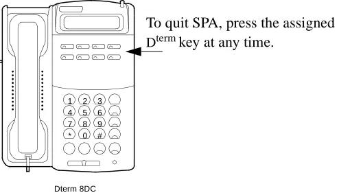
To quit using SPA, press the Dterm key assigned to SPA. If you are not sure which key to use, see your system administrator. The Dterm returns to its standard display.
Figure 1-7 Dterm Telephone Set
CALLING
1 2 3 4 5 6 7 8 9 * 0 #
Dterm 8DC
To quit SPA, press the assigned
Display Formats
Internal Call
Display Format
Internal call information displayed on the LCD is shown in the following table and described below:
• The line number represents the line number of an incoming call. A station can have up to five secondary lines.
• 1 - Prime number
• 2 - first secondary line
• 3 - next secondary line
(A blank character follows the line number.)
• The call signal is a single character indicating what actions the user performs on a call.
• This character is a blank if no action is performed.
• The “*” character displays when a chime tone is issued at the caller’s station.
Note: Only internal PBX callers can be notified with a chime tone.
• The “->” character displays when a number is called and no answer is received.
Note: The “<-” character displays when a number is called and the party answers. Internal PBX calls only.
• The name is an eight-character display retrieved from the name database. The name of the caller or one of the following messages displays in this field:
• “UNLISTED” — Displays if the name is not in the database.
• “OUTGOING” — Displays if the call is an outgoing call.
• The final field displays the caller’s extension.
Figure 1-8 Dterm Display (Internal Call)
1 Character 1 Character 8 Characters 1 Character 5 Characters
Field Line Number Call Signal Name Blank Extension
Values “1” - “6” “ ”, “->”, “<-” or “*”
OUTGOING UNLISTED Caller (ex: SMITH)
“ ” “0” - “ 99999”
External Call
Display Format
External calls with Automatic Number Identification (ANI) display different information than internal calls. The information displayed on the LCD is shown in the following table and described below:
• The line number represents the line number of an incoming call. A station can have up to five secondary lines.
• 1 - Prime number
• 2 - first secondary line
• 3 - next secondary line
• The call signal is a single character indicating what actions the user performs on a call.
• This character is a blank if no action is performed.
• The “->” character displays when a number is called.
• If an outside call has no ANI data, the line number and “OUTSIDE” display on the Dterm.
• The area code contains the three-digit area code of the caller.
• The phone prefix contains the three-digit phone number prefix of the caller.
• The phone suffix contains the four-digit phone number suffix of the caller.
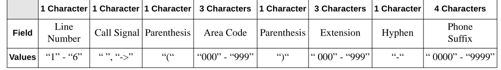
Figure 1-9 Dterm Display (External Call)
1 Character 1 Character 1 Character 3 Characters 1 Character 3 Characters 1 Character 4 Characters
Field Line
Number Call Signal Parenthesis Area Code Parenthesis Extension Hyphen
Phone Suffix
Values “1” - “6” “ ”, “->” “(“ “000” - “999” “)“ “ 000” - “999” “-“ “ 0000” - “9999”
1 (903)
555-1234
CCIS Call Display
Format
CCIS calls use Automatic Number Identification (ANI) and consists of a PBX Office Code and extension. The PBX Office Code is configured at the NEAX and may contain either integer or non-integer characters. If the PBX Office Code and extension both contain integer characters only, then CCIS extensions (without the PBX Office Code) and associated user names can be entered in the database. Calls display using the same format as internal calls. Other CCIS calls display using the information displayed on the LCD shown in the following table and described below:
• The line number represents the line number of an incoming call. A station can have up to five secondary lines.
• 1 - Prime number
• 2 - first secondary line
• 3 - next secondary line
• The call signal is a single character indicating what actions the user performs on a call.
• This character is a blank if no action is performed.
• The “->” character displays when a number is called.
• The CCIS number contains the PBX office code and extension.
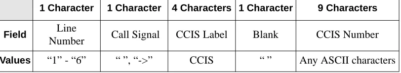
Figure 1-10 Dterm Display (CCIS Call)
1 Character 1 Character 4 Characters 1 Character 9 Characters
Field Line
Number Call Signal CCIS Label Blank CCIS Number
Values “1” - “6” “ ”, “->” CCIS “ ” Any ASCII characters
1 CCIS
#49234
Function Key
Assignments
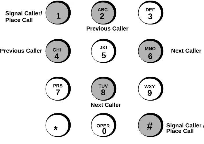
The Dterm keypad is assigned the functions found in Figure 1-11. These functions
are valid when Second Party Alert is enabled. SPA does not use the keys shown with a white background.
Figure 1-11 Dterm Keypad Layout Previous Caller
ABC
2
3
DEF
4
GHI
5
JKL
6
MNO
8
TUV
9
WXY
0
OPER
7
PRS
*
#
Next Caller
Signal Caller / Place Call
1
Signal Caller/ Place Call
Previous Caller
Chapter 2
INSTALLATION AND CONFIGURATION
Installation
This guide provides specific field entries that need to be made during the
installation and configuration of SPA. In addition to this guide, use instructions in the following manuals for this installation:
• Applications Manager (APM) Installation Manual - Contains step-by-step
instructions for installing the software from the release media.
• Applications Manager (APM) Operations Manual - Explains how applications
like SPA are configured in the APM environment and how the SPA database is created, using the entries and values provided in this chapter.
• NEAX2400 System Manuals - Give very detailed explanations about the
assignments that need to be made through the Maintenance Administration Terminal (MAT) commands on the NEAX2400.
The installation and set up of SPA involves the following sequence of steps:
• Software Installation — SPA software must first be loaded from the release media. Log in to the APM Platform Management Menu, select the Installation of Applications/Packages option, and follow the instructions provided in the
APM Installation Manual to complete this part of the installation.
• Application Configuration — SPA is internally supported by the APM and must be configured in the APM environment. Chapter 2, “INSTALLATION AND CONFIGURATION” in this manual provides the information that must be entered into this APM configuration file. Use the instructions provided in the
APM Operations Manual to make the entries contained in this section.
• Database Requirements — SPA requires a database that is constructed and maintained through the APM Database Administration option. The process begins with the creation of a master definition file and its related master database. Then, an application definition file is constructed which enables the processing of the master file into an application database. Chapter 3,
“DATABASE REQUIREMENTS” of this manual defines the information which must be included in these definition and database files. Use the instructions provided in the APM Operations Manual to make the entries contained in this section.
Installation (Continued)
The installation process, including its presentation in this and other manuals, is illustrated below:
SECOND PARTY ALERT
INSTALLATION REQUIREMENTS
Discussed in: Instructions in:
Chapter 2 Software Installation
Software
APM Installation Manual
Chapter 2 Application Configuration
Application Characteristics Primary Parameter Configuration
OAI Facilities (Optional) OAI Configuration Parameters (Optional)
User-Defined Parameters
APM Operations Manual
Chapter 3 Database Requirements
Master Field Definitions Master Database SPA Application Field Formats Process and Install SPA Database
APM Operations Manual
Chapter 4 NEAX2400 IMS
Maintenance Administration Terminal (MAT) Assignments
AIPT (Assignment of Interface I/O Port Data in IP) ASYD (Assignment of System-wide Data)
ASDT (Assignment of Station Data) AOKC (Assignment of OAI Key Codes) AKYD (Assignment of Dterm Function Key) ASHU (Assignment of Station Hunting-Group Data)
Software
Installation
Installation of the Second Party Alert software is initiated from the Applications Manager (APM) Platform Administration Main Menu. To display this menu, type apmadm at the UNIX prompt and press Enter. Using instructions in the APM
Operations Manual, select the Installation of Applications/Packages option from
this menu and load the SPA software from release media. As the installation process executes, follow the steps described below, entering the necessary information.
Step 1:
Active Second Party Alert Application Check
In order to install the SPA software, no SPA applications can be running on the system.
- If SPA applications are running, the error screen illustrated in Figure 2-1 is displayed and installation is terminated. Use the APM to terminate all active SPA programs before attempting another SPA installation.
Figure 2-1 Active Application Error
- If there are no active SPA programs, continue installation with “Step 2: Superuser (Root) Password”.
Step 2: Superuser (Root) Password
- If no SPA applications are running on the system, the following password screen displays. Use the instructions below to enter the superuser (root) password:
Figure 2-2 Password Screen
• Type the correct password for the root login and press Enter to continue. If you enter an invalid password, the following message displays: “Invalid root password. Do you wish to continue? (Y/N) [ ]”.
• Type y and press Enter to try again, or type n and press Enter to cancel the installation.
The Second Party Alert Application is currently active. Installation cannot continue until Second Party Alert has been terminated through the Applications Manager.
Press Enter to continue. [ ] <ENTER>
Super User (root) privileges are required.
Step 3: Existing SPA Installation Check
During this portion of the installation, the system determines if a previous version of SPA is installed.
- If SPA is not installed, the installation continues with “Step 4: Existing OAI Name Display Database Check” on page 15.
- If SPA is installed, then a warning screen is displayed, indicating that the current installation will be saved if installation is continued. Type y and press Enter to continue, or type n and press Enter to terminate.
Figure 2-3 Previous Version Detected
- If you chose to continue the installation after a previous version of SPA was detected, the following screen will be displayed. Type y and press Enter to delete this previously saved installation, or type n and press Enter to terminate.
Figure 2-4 Delete Previous Version
- If you chose to save the previous version, the following message is displayed after the existing SPA installation has been saved. Press Enter to continue with “Step 4: Existing OAI Name Display Database Check” on page 15.
Figure 2-5 Saved Previous Version Confirmation Message Second Party Alert is currently installed on this
machine. If you choose to continue, the current installation will be saved and all executable files will be upgraded. Database files will not be altered since this version uses the same database formats as previous versions.
Do you wish to continue? (y/n) [y] <ENTER>
A copy of "/oai/app/party.old" already exists on your system. This copy must be removed before the current system can be saved. If it is not removed, installation will be aborted.
Do you wish to remove "/oai/app/party.old"? (y/n) [y] <ENTER>
The current installation of Second Party Alert is now saved in "/oai/app/party.old".
Step 4: Existing OAI Name Display Database Check
In this step, the system determines if an OAI Name Display Database is installed on the system:
- If the Name Display Database is not installed, the MSF Op-code screen is displayed as described in “Step 5: Specify the MSF Op-code Number”.
- If the Name Display Database is installed, the following screen is displayed. Type y and press Enter to use the OAI Name Display Database, or type n and press Enter to create a separate Names Database.
Figure 2-6 Database Exists
Step 5: Specify the MSF Op-code Number
Use the following instructions to specify the MSF Op-code Number:
• Type the MSF Op-code used by SPA and press Enter.
- If you enter an invalid MSF Op-code, the message “ERROR: Invalid MSF number, please enter a value of 128...191!!!” is displayed. Press Enter, type a valid MSF Op-code, and press Enter again. When you enter a valid MSF Op-code, that code is displayed on the screen.
Figure 2-7 Verify MSF Op-code
• Type n and press Enter to cancel the entry and try again, or type y and press Enter to accept the entry and continue.
An OAI Name Display Database exists on this system. You may use this database with Second Party Alert, or create a separate Names Database.
Do you wish to use the existing OAI Name Display Database? (y/n) [y] <ENTER>
Please enter the MSF Op-code number (128...191) that will be used by Second Party Alert.
MSF Op-code: [128] <ENTER>
Step 6: Specify the OAI Key Code
Use the following instructions to specify the appropriate OAI Key Code:
• Type the OAI Key Code used by the PBX to generate the MSF Op-code specified in “Step 5: Specify the MSF Op-code Number” on page 15, and press Enter.
- If you enter an invalid OAI Key Code, the message “ERROR: Invalid OAI Key Code, please enter a value of 1...14!!!” is displayed. Type Enter, type a valid OAI Key Code, and press Enter again. When you enter a valid OAI Key Code, that code is displayed on the screen.
Figure 2-8 Confirm OAI Key Code
• Type n and press Enter to cancel the entry and try again, or type y and press Enter to accept the entry and continue.
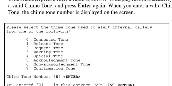
Step 7: Specify the Chime Tone
Use the following instructions to specify the chime tone used to alert internal callers:
• Type the Chime Tone used by SPA to alert internal callers and press Enter.
- If you enter an invalid Chime Tone, the message “ERROR: Invalid Chime Tone Number, please enter a value of 0...7!!!” is displayed. Press Enter, type a valid Chime Tone, and press Enter again. When you enter a valid Chime Tone, the chime tone number is displayed on the screen.
Figure 2-9 Verify Chime Tone
• Type n and press Enter to cancel the entry and try again, or type y and press Enter to accept the entry and continue.
Please enter the OAI Key Code (1...14) used by the PBX to generate MSF Op-code 128.
OAI Key Code: [1 ] <ENTER>
You entered [1] -- is this correct? (y/n) [y] <ENTER>
Please select the Chime Tone used to alert internal callers from one of the following:
0 Connected Tone 1 Release Tone 2 Request Tone 3 Warning Tone 4 Special Tone 5 Acknowledgment Tone 6 Non-acknowledgment Tone
Chime Tone Number: [0] <ENTER>
Step 8: Specify the Secondary Line Chime Flag
Use the following instructions to set the Secondary Line Chime flag:
• Type y and press Enter to enable the Secondary Line Chime, or type n and press Enter to disable it. The flag you selected is displayed on the screen.
Figure 2-10 Secondary Line Chime Flag
• Type n and press Enter to cancel the entry and try again, or type y and press Enter to accept the entry and continue.
Step 9: Specify the Local Area Code
Use the following instructions to enter the local area code:
• Type the local area code and press Enter. The area code you entered displays on the screen.
Figure 2-11 Local Area Code
• Type n and press Enter to cancel the entry and try again, or type y and press Enter to accept the entry and continue.
Step 10: Specify the NEAX Trunk Access Prefix
Use the following instructions to enter the NEAX Trunk Access Prefix:
• Type the NEAX Trunk Access Prefix and press Enter. The prefix you entered displays on the screen.
Figure 2-12 Verify Trunk Access Prefix
• Type n and press Enter to cancel the entry and try again, or y and press Enter to accept the entry and continue.
Do you want each station to chime when a call is received on a secondary line (y/n) [y] <ENTER>
You entered [y] -- is this correct (y/n) [y] <ENTER>
Please enter your local area code: [972] <ENTER>
You entered [972] -- is this correct (y/n) [y] <ENTER>
Please enter you NEAX trunk access prefix: [9] <ENTER>
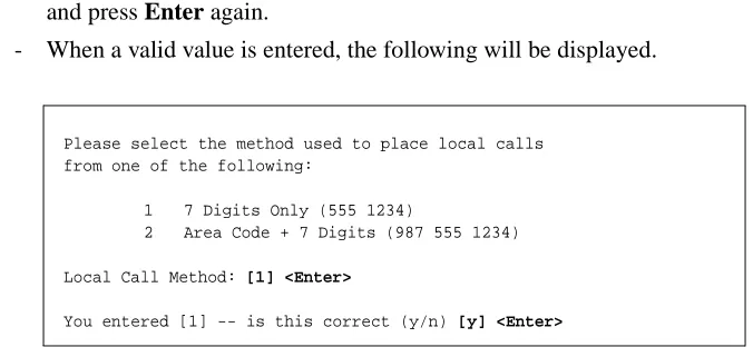
Step 11: Specify the Local Call Method
Use the following instructions to specify the method used to place local calls:
• Type the number that specifies the correct local call method for your area, and press Enter.
- If an invalid value is entered, the message “ERROR: Invalid Local Method, please enter a value of 1...2!!!” is displayed. Press Enter, type a valid value, and press Enter again.
- When a valid value is entered, the following will be displayed.
Figure 2-13 Local Call Method
• Type n and press Enter to cancel the entry and try again, or y and press Enter to accept the entry and continue.
Please select the method used to place local calls from one of the following:
1 7 Digits Only (555 1234)
2 Area Code + 7 Digits (987 555 1234)
Local Call Method: [1] <Enter>
Step 12: SPA Auto-Config — New Configuration
- If a previous version of SPA is installed on the system, installation continues with “Step 13: SPA Auto-Config — Update Existing Configuration” on page 20.
- If SPA is not installed, the following information screen is displayed, indicating that the default configuration values will be used for auto configuration.
Figure 2-14 SPA Auto-Config (New Config)
• Type Enter to begin the auto configuration process. During the SPA auto configuration, the following screen is displayed:
Figure 2-15 SPA Auto-Config Complete (New Config)
• When the auto configuration has completed, type Enter and continue with
“Step 14: Database Template Installation” on page 21.
The default Second Party Alert Application Configuration will now be installed by the autoconfig program. After the Second Party Alert Installation has concluded, be sure to check the configuration using the Applications Manager (APM) and modify any settings that are different on your system.
Press Enter to continue [ ] <ENTER>
Second Party Alert Auto-Configuration
/oai/utils/autocfg running...
/oai/utils/autocfg: 2nd_Party_Alert application configured.
/oai/utils/autocfg terminated normally.
Second Party Alert Auto Configuration Complete
Step 13: SPA Auto-Config — Update Existing Configuration
- If a previous version of SPA is installed on the system, then the followinginformation screen is displayed, indicating that the current configuration will be updated.
Figure 2-16 SPA Auto-Config (Existing Config)
• Type Enter to begin the auto configuration process. During the SPA auto configuration the following screen is displayed:
Figure 2-17 SPA Auto-Config Complete (Existing Config)
• At the “Reconfigure (y/n)?” prompt, type y and press Enter to update the existing SPA configuration. When the auto configuration has completed, press Enter to continue with “Step 14: Database Template Installation”.
The current Second Party Alert Application Configuration will be modified to support the new version. When the autoconfig program is executed by the installation program, you will be informed that "2nd_Party_Alert" is already configured.
When the autoconfig program asks if you want to reconfigure, be sure to answer with ’Y’ or ’y’ to ensure that the modified Second Party Alert Configuration is installed.
After the Second Party Alert Installation has concluded, be sure to check the configuration using the Applications Manager (APM) and validate that all settings are correct for you system.
Press Enter to continue [ ] <ENTER>
Second Party Alert Auto-Configuration
/oai/utils/autocfg running...
/oai/utils/autocfg: 2nd_Party_Alert is already configured. /oai/utils/autocfg: Reconfigure (y/n)? y <ENTER>
/oai/utils/autocfg: 2nd_Party_Alert application configured.
/oai/utils/autocfg terminated normally.
Second Party Alert Auto Configuration Complete
Step 14: Database Template Installation
• After auto configuration, the installation script will install the database template files. The following screen will be displayed:
Figure 2-18 Database Template Installation
• After the database templates have been installed, SPA installation is complete. Now go to “Configure Application” on page 23 to configure the SPA
applications.
Second Party Alert Database Template Installation
Copying Second Party Alert Names Master Database template Copying Second Party Alert Names Application Database template Copying Phone Line Master Database template
Copying Phone Line Application Database template Copying Tenant Master Database template
Copying Tenant Application Database template
Configuration
The following sections describe the configuration of Second Party Alert (SPA).
Access System
Administration
Menu
To access the System Administration Menu:
• Select the APM option from the APM Platform Management menu.
• Enter the System Administrator password at the APM password screen.
Change Facility
Number
The Number of Facilities must be set to 9 or greater in the OAI Library
Configuration before SPA 1.5 (or previous versions) will work. (The default is 8.)
Using the APM, perform the following steps to change the default value of Number
of Facilities:
• Select System Configuration from the System Administration menu.
• Select OAI Library Configuration.
• Select Modify.
• Press the Enter key.
• Use the arrow keys to move to the Number of Facilities field.
• Enter 9 (or greater) and press the Enter key.
Configure
Application
SPA is configured into the APM system using the Add function of the Application Configuration option on the APM System Administration menu. Enter the Application Configuration option from the System Administration menu.
This section contains the information that you should enter into the configuration file for SPA. For specific instructions on what these parameters mean and how to make these entries, use the APM Operations Manual.
Step 1: Application Characteristics
When adding SPA to the APM Application Configuration file, define it as follows:
Note: This step is done automatically during installation if you answer YES to the autoconfig prompt.
Parameter Default Entry Description
OAI Application Y Indicates whether or not (Yes or
No) SPA communicates with the NEAX2400 using OAI processes.
CRT Application N Indicates whether or not (Yes or
No) SPA requires a terminal screen that is of the same type as the one used by the APM
Communication Queue N Indicates whether or not (Yes or No) this non-OAI application needs an IPC queue to
Step 2: Primary Configuration Parameters
On the APM Configuration Entry screen, make an entry for each SPA parameter shown below. If the parameter is followed by an asterisks (*) in the table, you must make the entry exactly as shown. Other entries serve only as examples — actual entries are site-dependent.
Note: This step is done automatically during installation if you answer YES to the autoconfig prompt.
Parameter Default Entry Description
Application Name 2nd_Party_Alert Specifies the name to be displayed in the APM menus. This name is displayed however it is entered here (i.e., capital letters, lower case, etc.)
Executable Filename* /oai/app/party/bin/spa Indicates the path name of the executable file.
Group* (no entry) Indicates the group to which SPA is
associated.
Response Mode* I Indicates the action that the APM is
to take with SPA should a member of the group terminate, such as I(gnore).
Initialization Batch N Indicates whether or not (Yes or
No) SPA is to be initialized automatically when the OAI system is initialized.
Termination Mode* M Indicates how the APM is to notify
SPA to terminate (e.g., message).
Standard Output /dev/null Designates the file into which SPA output is redirected.
Number of Restarts 0 Indicates how many times the APM
Step 3: OAI Facilities
According to instructions in the APM Operations Manual, designate the following NEAX2400 facilities for SPA using the Facilities command on the Configuration Entry screen. These facilities are automatically set up when you run autoconfig during installation.
Note: The same MSF Op-Code that is specified here must be assigned to SPA at the NEAX MAT. For more information, see Chapter 4, “MAT ASSIGNMENTS”. Only one MSF can be specified or the application terminates immediately.
MRFI Mode Release (I) MRFR Mode Release (R)
MSF OAI Mode Set NTF Number Transfer
SMFR Status Request (R) SMFN Status Notification (N)
TCFD Terminal Control (D) TCFI Terminal Control (I)
Step 4: Secondary OAI Configuration Parameters
Using the OAI-Conf command on the APM Configuration Entry screen, make an for each of the following parameters. If the parameter is followed by an asterisks (*) in the table, you must make the entry exactly as shown. Other entries serve only as examples — actual entries are site-dependent. Use the instructions provided for this option in the APM Operations Manual. These parameters are automatically set up when you run autoconfig during installation.
Parameter Default Entry Description
Database Name #1* /oai/db/cur/nmdsp Indicates the path name of the database containing the names and extensions of everyone in the organization.
Note: This entry refers either to the name of the SPA database created through the APM (see
Chapter 3, “DATABASE REQUIREMENTS”) or to the Name Display database that is to be used by SPA. If the Name Display database is to be used, enter its name here.
Database Name #2* /oai/db/cur/phonline Indicates the path name of the database containing primary extensions and the secondary (virtual) lines associated to them.
Timeout Value #1 60 Designates the number of seconds
that SPA waits before clearing information from the Dterm LCD
panel.
Timeout Value #2 0 Indicates that there is not a timeout
period for the second timeout value.
Tenant Number 1 Specifies the number of the tenant
that SPA serves.
Source Link Name OAI1TCP Identifies the port on the source side of the communication link.
Destination Link Name PBX1TCP Identifies the port on the destination side of the communication link.
Association Recovery 30 Designates the number of seconds
SPA waits before trying to
Step 5: User-Defined Parameters
Make the following additional parameter entry through the UserDefined command on the OAI Configuration screen. These parameters are automatically set up when you run autoconfig during installation.
Parameter Typical Entry Description
User Defined #1 7 The OAI key code assigned on the
MAT via the AOKC command.
User Defined #2 2 This is the chime tone value
(assigned at installation) that is heard by the caller and called party. The tones are:
• 0Connected tone*
• 1Release tone
• 2Request tone
• 3Warning tone*
• 4Special tone*
• 5Acknowledgment tone
• 6Non-acknowledgment tone
• 7Confirmation tone
Note: For 4200 V6 or earlier version of the PBX software, the connect tone, warning tone, and special tone do not
produce any audio tones.
User Defined #3 (no entry) This allows the station to chime
when a call is received on a secondary line. If the value is set to
Y, a chime sounds. If it is set to N,
no chime sounds. the default is N.
User Defined #4 8 This value describes the size of the
display name used by the name display database defined in Second Party Alert. Valid values for this field are 8 and 16. The default is 8.
User Defined #5 Enter the local area code in this
field (assigned at installation).
User Defined #6 Enter the NEAX trunk access
prefix (assigned at installation).
Step 5: User-Defined Parameters (Cont)
This completes the configuration of SPA in the APM. Now go to Chapter 3, “DATABASE REQUIREMENTS” to create its database support.
Parameter Typical Entry Description
User Defined #8 7 This field specifies the number of
digits used to place a local call. Valid values for this field are 7 (7 digit phone number only) and 10 (area code + 7 digit phone number). If this field is blank or an invalid value is specified, the default value of 7 is used by the program.
User Defined #14 /T L1 U9 D/oai/log/dbg/party.out This is not part of the default setup. Enter the value listed to enable debug logging.
Chapter 3
DATABASE REQUIREMENTS
This chapter assumes that SPA is not going to use the OAI Name Display application database and must have one built. In this case, SPA requires two databases that are created through the Database Administration option on the APM System Administration Menu.
Database creation in the APM involves the following 4-step process:
• Step 1 - Create a Master Definition File: This step involves creating the master definition file that defines the fields in the master database file.
• Step 2 - Build a Master Database File: This step involves entering data (e.g., actual phone lines) into the master database fields that were just defined in the master definition file in Step 1.
• Step 3 - Create an Application Definition File: In this step, a definition file is created for the SPA database. This file defines the formats by which data from the master file is to be converted to meet the needs of SPA.
• Step 4 - Process and Install the Application Database: In this step, the Process and Install Application Databases options on the APM Database Administration menu creates the file that will be used by SPA. When the Process option is activated, data is drawn from the master database and converted to the formats specified in the application definition file. The Install option is then activated to enable SPA to copy its database.
Instructions
The information required for the SPA database is provided in the table on the following page. Using this information with the procedural instructions provided in the APM Operations Manual, enter the Database Administration option on the APM System Administration Menu and build the SPA database. Any messages displayed during these steps are addressed in the Process and Error Messages chapter of the APM Operations Manual.
Note: Remember to complete Step 4, Process and Install the Application Database, for each database after you enter the following information.
Step 1 - Create
Master Definition File
Step 2 - Build
Master Database File
Step 3 - Specify
Application Formats
Step 4 - Process
Name Display
Database
Information
The Name Display database field entries are shown in the following table and defined below the table. Name the Master Definition File name_m and the Application Definition File nmdsp.
Note 1: You do not have to create this database if the Name Display application is installed, and its database is going to be used.
Note 2: Name the name_m file in the Define Master Database Fields option, chosen from the Build Master Database option on the Database Administration menu. Name the nmdsp file in the Specify Application Database Fields option.
Field Definitions
• Extension - The five-digit primary extension number. This is the number that is displayed with the caller’s name when this phone is used to place the call.
• Display Name - The name that is to be displayed on the Dterm LCD panel.
The name must be entered in the format, F.Lucas, with the first name initial separated from the last name by either a period (.) or a blank space.
Field Description
Master Definition File Application
Definition File Master Database
Type Size Min. Value
Max.
Value Data Type Typical Entry
Extension N 5 0 99999 ASCII 4290
Phone Line
Database
Information
The Phone Line database field entries are shown below in the table and defined below the table. Name the Master Definition File phone_m and the Application Definition File phonline.
Note: Name the phone_m file in the Define Master Database Fields option, chosen from the Build Master Database option on the Database Administration menu. Name the phonline file in the Specify Application Database Fields option.
Field Definitions
• Phone Line 1 - The five-digit primary extension number. This is the number that is displayed with the caller’s name when this phone is used to place the call.
• Phone Line 2 - 6 - The five-digit secondary, or virtual, lines that are
associated with the primary extension that was entered in the first field. These virtual lines must be assigned to this primary line and to a hunt group through the NEAX Maintenance Administration Terminal (see MAT Assignments).
Field Description
Master Definition File Application
Definition File Master Database
Type Size Min. Value
Max.
Value Data Type Typical Entry
Phone Line 1 N 5 0 99999 Long Integer 4290
Phone Line 2 N 5 0 99999 Long Integer 4291
Phone Line 3 N 5 0 99999 Long Integer 4292
Phone Line 4 N 5 0 99999 Long Integer 4293
Phone Line 5 N 5 0 99999 Long Integer 4294
Tenant Number
Database
Information
The Tenant Number database field entries are shown below in the table and defined below the table. The database contains a list of extensions and associated tenant numbers used by the PBX. A tenant number can be associated with an individual numeric extension or a range of numeric extensions. A given tenant number can have more than one record if all of the extensions associated with it are not consecutive. Tenant numbers can also be associated with individual extensions that contain non-numeric characters such as ‘*’ or ‘#’. Make the Master Definition File tenant_m and the Application Definition File tenants.
Note: Name the tenant_m file in the Define Master Database Fields option, chosen from the Build Master Database option on the Database Administration menu. Name the tenant file in the Specify Application Database Fields option.
Field Definitions
• First Extension- the first extension in the range of extensions.
• Last Extension- the last extension in the range of extensions.
• Tenant Number- this field contains the associated tenant number.
This completes creation of SPA database support. Now go to Chapter 4, “MAT ASSIGNMENTS” to make the necessary command assignments at the NEAX2400 MAT.
Field Description
Master Definition File
Application Definition
File
Master Database
Type Size Min. Value
Max. Value
Data Type Typical Entry
First Extension ASCII 10 ASCII 1000
Last Extension ASCII 10 ASCII 1099
Chapter 4
MAT ASSIGNMENTS
This guide assumes that data settings that affect the operation of all OAI software on a system-wide basis have already been assigned on the NEAX Maintenance Administration Terminal (MAT). Such settings include system index values and assignment of Interface I/O Port Data in the Interface Processor (IP). For more information about these system data settings and the MAT commands described below for SPA, refer to the OAI Module Installation Manual for the NEAX2400
IMS, the NEAX2400 IMS Command Manual, the NEAX2400 IMS Job Specification Manual, and the NEAX2400 IMS Programming Manual.
The user-defined parameter #1 assigned during the application configuration on
page 27 identifies the function key that the phone user presses to display call information. You must now assign this key at the MAT to the Mode Set Facility (MSF) for all Dterms that will be able to display calling party information.
Using the AOKC command, assign the MSF facility and its Op-Code to one of the 14 OAI Key Codes in the MAT. Each of these OAI Key Codes corresponds to an AKYD Function Key Index (FKI) value that is then assigned to the specific Dterm
function key. This process is illustrated below.
Figure 4-1 OAI Function Key Assignment
A knowledge of the Dterm stations in the NEAX system and which ones will be set
up to access SPA is necessary for using the following commands.
APM Application Configuration
Designation ofFacility (Type)and its
Op-Codefor Use by Application
MAT AOKC Command
Assignment ofan OAI Key Code(between 1 and 14)to the Same Facility Typeand
Op-Code MAT AKYD Command Assignment of Corresponding MAT Function Key Index to aspecific Dterm
Function Key
. . . . . . . . . . . . . . . . PBX Correspondence of
AOKC AKYD
OAI Function
Key Codes Key Indices
AIPT Command: (Assignment of Interface I/O Port Data in IP)
This command can be used to assign TCP/IP address of the system’s IP. Let system and UAP both in ethernet.
• IP-NO: Assign face Processor Number.
• Port Number
• PNI: Assign 1
• KIND: Assign 3 for choose TCP/IP protocol.
• Assign ETHER-PKGNO
• Assign TCP/IP address
ASYD Command: Assignment of System Data
If the Name Display application is not installed and a Name Display Database has been created through the APM for SPA use, the Name Display feature on the NEAX2400 does not need to be enabled, and this MAT assignment does not have to be made. If the Name Display application is installed and its database is going to be used by SPA, the Name Display feature on the NEAX2400 must be enabled. This feature allows SPA to access the Name Display database and retrieve the name associated with the calling extension. Use the ASYD command to enable this feature if necessary:
• System 1, Index 78, bit 3
Enter either of the following two values:
• 0: Display name only.
• 1: Display calling/called number with name.
• System 1, Index 78, bit 5
Enter 1 (yes) to set name display feature into service.
ASDT Command: Assignment of Station Data
Each Dterm that is to carry SPA must be set up to handle multiple incoming calls in
a manner that is supportive of the SPA function. In addition to its primary incoming line, each supported Dterm must have a user-defined number of virtual lines
assigned to it, and those primary/virtual lines assigned into a pilot hunt group. Then, when the Dterm user is on the primary line, any incoming call is wrapped to
the next virtual line in that hunt group. Use the ASDT and ASHU commands to complete these assignments for each supported Dterm:
1. Enter the same tenant number that is configured for the application in the APM Application Configuration option (Tenant #1, page 26).
2. Identify virtual lines for each supported Dterm. These lines should agree with the
AOKC Command: (Assignment of OAI Key Codes)
This command is used to associate the MSF facility and its Op-Code that was configured in the APM for the application to one of the OAI Key Codes in the MAT.
1. Select an unused OAI Key Code, from 1 to 14. To determine what Key Codes are available for assignment, use the LOKC command to list the AOKC Key Codes that are already assigned.
2. Enter the type of facility using the value that designates the MSF.
3. Enter the same MSF Op-Code that was configured for SPA in the APM. Re-trieve it using the Providers command on the APM Configuration Entry screen.
AKYD Command: (Assignment of D
termFunction Key)
The AKYD command can only be used to assign key data on those Dterms that have
already been assigned through the ASDT command.
MAT Function Key Indexes #34 to #47 have been designated for use in the OAI system and correspond to the 14 OAI Key Codes as illustrated in Figure 4-1 on page 33. The AKYD command is used to assign a Dterm function key to the specific
MAT Function Key Index that, in turn, corresponds to the previously assigned OAI Key Code. This command must be used to assign the function key on each Dterm
that is to be set up with access to SPA.
1. Dterm function key #8 was designated in the application configuration as the key
that is to be pressed to activate SPA from the Dterm (Step 5: User-Defined
Pa-rameters on page 27).
2. Enter the same tenant number that is configured for the application in the APM Application Configuration option (Tenant #1, page 26.)
3. Enter the station number of the Dterm on which the function key is being
as-signed.
4. Enter the Dterm function key to the MAT Function Key Index that in turn
corre-sponds to the previously assigned OAI Key Code.
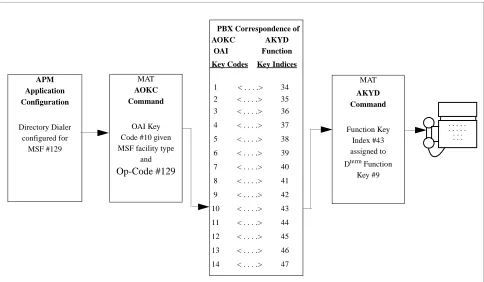
Figure 4-2 OAI Function Key Assignment
In the example above, MSF was selected in the APM Application Configuration, and its Op-Code was determined to be #129. MSF #129 is then assigned through the AOKC command to an OAI Key Code. In this example the Key Code is #10. The Dterm function key that is to be used to access SPA is configured as function
key #8. Since OAI Key Code #10 corresponds in the PBX to MAT Function Key Index #43, Dterm function key #8 is assigned to Function Key Index #43 using the
AKYD command. Now whenever a phone user presses function key #8 on any assigned Dterm, MSF 129 initiates communication with SPA for display of calling party information
ASHU Command: Assignment of Station Hunting-Group Data
1. Enter the same tenant number that is configured for the application in the APM Application Configuration option (Tenant #1, page 26).
2. For each primary station number, enter the virtual line numbers that are to be in the hunt group. These virtual line numbers must agree with those assigned in the ASDT command and those entered in the database.
SPA is now installed and ready to be initialized. Enter the APM Operations Menu and initialize SPA through the Non-CRT Application option, according to instructions provided in the APM Operations Manual.
APM Application Configuration Directory Dialer configured for MSF #129 MAT AOKC Command OAI Key Code #10 given MSF facility type
and Op-Code #129 MAT AKYD Command Function Key Index #43 assigned to Dterm Function
Key #9
. . . . . . . . . . . . . . . . PBX Correspondence of
AOKC AKYD
OAI Function
Key Codes Key Indices