Recomputing with Permuted Operands:
A Concurrent Error Detection Approach
Xiaofei Guo and Ramesh Karri
Polytechnic Institute of New York University [email protected], [email protected]
Abstract. Naturally occurring and maliciously injected faults reduce the reliability of cryptographic hardware and may leak confidential information. We develop a concurrent error detection (CED) technique called Recomputing with Per-muted Operands (REPO). We show that it is cost effective in Advanced Encryption Standard (AES) and a secure hash function Grøstl. We provide experimental results and formal proofs to show that REPO detects all bit and single-byte faults. Experimental results show that REPO achieves close to 100% fault coverage for multiple single-byte faults. The hardware and throughput overheads are compared with those of previously reported CED techinques on two Xilinx Virtex FPGAs. The hardware overhead is 12.4-27.3%, and the throughput is 1.2-23Gbps, depending on the AES architecture, FPGA family, and detection latency. The performance overhead ranges from 10% to 100% depending on the security level. Moreover, the proposed technique can be integrated into various block cipher modes of operation. We also discuss the limitation of REPO and its potential vulnerabilities.
1
Introduction
Cryptographic primitives such as secret key encryptions and cryptographic hash functions are important in the security of data transmission in modern information systems. Secret key encryptions such as block ciphers and stream ciphers are widely used to provide data confidentiality [26]. A block cipher is a deterministic algorithm operating on groups of fixed-size bit strings, called blocks, with an unvarying transformation that is specified by a key. Block ciphers are important cryptographic primitives in the design of many cryptographic protocols and are widely used to encrypt data. A stream cipher exclusive-ors a plaintext bit with the corresponding keystream bit and generates the ciphertext bit. The National Institution of Standards and Technology (NIST) specifies Advanced Encryption Standard (AES) as the standard secret key encryption [33]. AES can also be used as stream ciphers such as LEX [?].
Cryptographic hash functions have many information security applications, notably in digital signatures, message au-thentication codes, and other forms of auau-thentication [26]. They are used to index data in hash tables, for fingerprinting, to detect duplicate data or uniquely identify files, and as checksums to detect accidental data corruption. A cryptographic hash function takes an arbitrary bit string and returns a fixed-size hash value, so that an accidental or intentional change to the data will change the hash value with a very high probability. NIST started a secure hash function (SHA-3) competition in 2007. Several candidates in the competition utilize the AES-style structure as a building block such as ECHO, Grindahl, Grøstl, LANE, and SHAvite-3 [32]. Grøstl was selected in the final round competition after extensive assessment. Because Grøstl employs the AES-style structure, it makes all known, generic attacks on the hash function much more difficult.
As transistor size keeps scaling, increasing rates of faults [30], device variations [6], and aging [2] are posing serious challenges for VLSI designers. Faults that occur in VLSI chips are classified into two categories: transient faults, that eventually die away, and permanent faults. The origin of these faults could be internal phenomena in the system such as threshold changes, shorts, opens, etc., or external influences, such as electromagnetic radiation. These faults affect the memory as well as the combinational parts of a circuit and are detected using concurrent error detection (CED) [41].
Recently, differential fault analysis (DFA) has been proposed to extract secret keys in AES [3, 4, 13, 18, 27, 31, 35, 36, 40, 42] and Grøstl [11]. In DFA, the assumption is that the attacker is able to control the timing and the location of the fault, but has little influence on the actual fault value. This model is typical for laser injection, which is one of the most powerful tools for fault attacks. On the other hand, other means are more affordable and accessible, though less precise; clock glitches and drops in power supply are easier to set up and can inject exploitable faults as well. Using a completely general fault model, it was proven that the last round key can still be recovered.
faulty ciphertexts. Therefore it prevents potential exploitation. Infection countermeasures prevent the exploitation of faulty ciphertexts by changing the logical effect of a fault in such a way that it significantly modifies the results. Therefore attackers cannot exploit the faulty ciphertexts [21].
NIST formulates security requirements for cryptographic modules in FIPS 140 [34]. It defines four levels of security. At security level four, the highest, it emphasizes that the physical security mechanisms must provide a complete envelope of protection around the cryptographic module with the intent of detecting and responding to all unauthorized attempts at physical access. Therefore, we focus on detection in this work.
1.1 Related Work
Previous CEDs can be classified into four types of redundancy: hardware, time, information, and hybrid redundancy. Hardware redundancyduplicates the function and detects faults by comparing the outputs of two copies.
Time redundancy: The function is computed twice on the same input and the results are compared. A simple time redundancy technique for AES is proposed in [24]. The authors simply recompute the encryption after a normal compu-tation, and results are compared. A variation of time redundancy called double-data-rate (DDR) is described in [23]. In this technique, the function is computed on both clock edges. This speeds up the computation. Under some conditions, this technique allows the encryption to be computed twice without affecting the global throughput. This technique becomes more difficult to implement as technology scales.
In [8], a variation of recomputing with shifted operands is proposed for AES. During the recomputation, each row is cyclically shifted before entering substitution-boxes (S-boxes), and the order is restored after S-boxes. This technique is quite effective because it uses different hardware to compute the data in the computation and recomputation. It detects both transient and permanent faults in S-boxes. However, it cannot detect permanent faults in other round operations.
Information redundancy: Many error detection techniques are based on error detecting codes. A few check bits are generated from the input message; then they propagate along with the input message and are finally validated when the output message is generated. In the basic parity technique [5], each predicted parity bit is generated from an input byte. Then, the predicted parity bits, and actual parity bits of output are compared to detect the faults. This technique incurs large hardware overhead. In another technique, only one bit parity is used for the entire 128-bit output, and the parity bit is checked once for the round [43]. However, these techniques only apply to lookup table-based (LUTs) S-box implemen-tation. In [28], parity is obtained for S-box implementation using logic gates. In [22], a general parity-based technique is proposed to protect the S-box regardless of its implementation. This parity technique is later extended to Grøstl [29]. All these parity techniques share the same limitation. If an even number of faults occurs in the same byte, none of these techniques detect them. To address this limitation, systematic robust code is proposed [16, 19]. It provides uniform fault coverage. The key idea is to construct a prediction circuit at the round input to predict the nonlinear property of the round output. While this technique provides high fault coverage compared to parity code, the hardware overhead of this technique is 77%. Another approach uses cyclic redundancy check codes overGF(28)[9]. It detects all odd number of faults.
Hybrid redundancy: In [17], the authors consider CED at the operation, round, and algorithm levels. In these tech-niques, an operation, a round, or the entire encryption and decryption are followed by their inverses, and the results are compared with the original input. Although these techniques detect most faults, they require both encryption and decryp-tion to be on chip and can suffer from more than 100% throughput overhead. An improvement of this idea is proposed to merge the encryption and decryption datapath to achieve small performance and area overhead [39]. In this technique, both encryption and decryption are deeply pipelined to increase clock frequency. In encryption, each stage will perform a function in one clock cycle, and the inverse function in the next clock cycle. The authors optimize the area by sharing hardware between functions and their inverse. In [37], the authors propose a technique that computes data on different pipeline stages. However, this technique is only applicable to pipeline architecture.
1.2 Contributions
=? Error Reg f
f
(a)
=? Error Reg f
f
c d
(b)
=? Error Reg f
f
c c-1
(c)
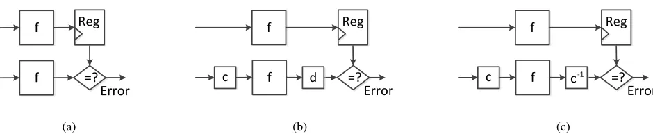
Fig. 1: (a) The concept of time redundancy (b) Variation of time redundancy. (c) Time redundancy with inverse functions.
– We present REPO for AES-style functions and we generalize REPO for ALU and other logic operations.
– We reduce the performance overhead of REPO with adaptive checking and Randomized CED Round Insertion from 100% to 50%.
– We prove that REPO detects all single-bit and single-byte faults.
– REPO achieves an order of105lower fault miss rate than the best parity techniques for multiple burst and multiple random faults.
– We apply REPO to AES-inspired hash function Grøstl, and it achieves even higher fault coverage.
This paper is organized as follows: In Section 3.1, we introduce the AES algorithm. In Section 3.2, we explain the key idea of the proposed REPO technique, and we show the fault coverage, hardware overhead, and detailed analyses of the technique. We also compare the fault coverage of different invariances. In Section 4, we extend the idea to the AES-inspired Grøstl hash function and analyze the scalability of our technique. Section 6 concludes the paper.
2
Recomputing with Permuted Operands
In this section, we introduce REPO and how it is a generalization of recomputing with shifted operands (RESO) and recomputing with rotated operands (RERO).
As shown in Fig. 1(a), letxbe the input to a computation unitf andf(x)be the output. In time redundancy,f(x)is computed twice. The result of the first computation is stored in a register and then compared with the result of the second computation. The drawback of this technique is that faults are detected only if they do not affect both of the computations. Therefore, permanent faults and transient faults that affect both of the computations will not be detected.
To solve this problem, one can build two functionscandd, such thatd(f(c(x))) =f(x)as shown in Fig. 1(b). We first computef(x)and thend(f(c(x))). Ifcanddare properly chosen, then a fault in unitf will affectf(x)andd(f(c(x)))in a different way. Therefore, the outputs of the two computations will not match. When the functionscanddare inverses of each other, i.e.,d(c(x)) =xfor allx, we havec−1(f(c(x))) =f(x)as illustrated in Fig. 1(c). Fig. 1 is the basis of time redundancy techniques. Functionccan be any bijection function including shifting, rotation, permutation, etc.
Definition:Apermutationof a setSis defined as a bijection fromSto itself. This is related to the rearrangement ofS in which each elementstakes the place of the correspondingf(s). The collection of such permutations forms a symmetric group.
The key to its structure is the possibility of composing permutations: performing two given rearrangements in suc-cession defines a third rearrangement, the composition. Permutations may act on composite objects by rearranging their components, or by certain replacements (substitutions) of symbols. IfS is a finite set ofnelements, then there aren! permutations. Therefore, permutation includes cyclical shift, i.e., rotation. Because shifting and rotation are specials form of permutation, REPO is a generalization of RESO and RERO.
=? Error Reg
permutation permutation
X Y
Function f
Inverse permutation
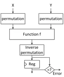
Fig. 2: REPO Architecture
3
REPO for AES
In this section, we will introduce the AES algorithm and how REPO is used for AES.
3.1 Advanced Encryption Standard
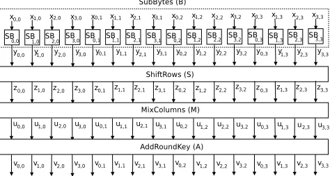
In this paper, we consider 128-bit AES as specified by NIST [33]. AES encrypts a 128-bit plaintext into a 128-bit ciphertext with a user key using 10 nearly identical rounds plus an initial special round (round 0). One AES encryption round consists of SubBytes, ShiftRows, MixColumns, and AddRoundKey, denoted byB,S,M, and A, respectively, as shown in Fig. 3. In round 0, only AddRoundKey is performed and in round 10, MixColumns is not performed. Each operation in every round acts on a 128-bit inputstate, where each state element is a byte inGF(28). In this paper, each byte is denoted by
sr,c(0≤r, c≤3), and it indicates that this byte is in rowrand columncin state matrix.
S=
s0,0s0,1s0,2s0,3 s1,0s1,1s1,2s1,3 s2,0s2,1s2,2s2,3 s3,0s3,1s3,2s3,3
= [sr,c]r,c=0..3 (1)
In SubBytes, all the bytes are processed separately by 16 S-boxes (SBs). Each S-box performs a nonlinear transforma-tion of the input byte. LetXbe the input to the SBs. The resulting output is:
Y =B(X) = [yr,c]r,c=0..3 (2)
In ShiftRows, the rows of the state are shifted cyclically byte-wise using a different offset for each row. Row 0 is not shifted, while rows 1, 2, and 3 are cyclically shifted to the left by 1 byte, 2 bytes, and 3 bytes, respectively. The resulting output is:
Z =S(Y) =
y0,0y0,1y0,2y0,3 y1,1y1,2y1,3y1,0 y2,2y2,3y2,0y2,1 y3,3y3,0y3,1y3,2
= [yr,(r+c)mod4]r,c=0..3= [zr,c]r,c=0..3 (3)
In MixColumns, the output state is obtained by multiplying a constant matrix with the output of ShiftRows. The result-ing output is:
Fig. 3: One AES encryption round (The last round does not have MixColumns)
02 03 01 01 01 02 03 01 01 01 02 03 03 01 01 02
z0,0z0,1z0,2z0,3 z1,0z1,1z1,2z1,3 z2,0z2,1z2,2z2,3 z3,0z3,1z3,2z3,3
(4)
In AddRoundKey, the input state is added (modulo-2) to the round key, i.e., the 128-bit stateU with matrix K = [kr,c]r,c=0..3. The resulting output is:
V =A(K, U) = [ur,c]r,c=0..3+ [kr,c]r,c=0..3= [vr,c]r,c=0..3 (5)
The S-box of AES is composed as a multiplicative inversion inGF(28)modulo the irreducible polynomialx8+x4+ x3+x+ 1, followed by an affine transformation.
3.2 An invariance of AES
In [20], the authors have shown that AES exhibits various round and mapping invariances1. Up till now, invariances in
cryptographic algorithms have been identified by cryptanalysts. Because regularity of algorithm components can lead to new cryptanalytic insights and approaches, the authors were investigating these as possible source of weakness in AES. In contrast, we use these invariances for CED to protect the AES against random faults and malicious attacks by checking these properties [15]. We analyze three round level invariances of AES. We give a formal proof of the invariance propertyα1, which is the most effective invariance according to our experimental results. We analyze the effectiveness of the remaining invariances in Section 3.7.
Theorem 1. An AES round can be represented as
A(K, M(S(B(X))))
where X is the 128-bit input to the round. Byte permutationαexists such that the following holds true:
A(K, M(S(B(X)))) =α−1(A(α(K), M(S(B(α(X)))))) (6)
whereα−1denotes the inverse function ofα. One of the byte permutation is:
α1(X) =α1([xr,c]r,c=0..3) =
x0,3x0,0x0,1x0,2 x1,3x1,0x1,1x1,2 x2,3x2,0x2,1x2,2 x3,3x3,0x3,1x3,2
1
= [xr,(c+3)mod4]r,c=0..3 (7)
α−11([xr,(c+3)mod4]r,c=0..3) = [xr,c]r,c=0..3 (8)
Proof. Let us start from the right-hand side of the equation. First, we apply permuted inputX0 =α1(X)to SubBytes, and from (2) and (7), we get:
Y0 = [yr,c0 ]r,c=0..3= [yr,(c+3)mod4]r,c=0..3=α1(Y) (9)
GivenY0as the input to ShiftRows, we get:
Z0 =S(Y0) =
y00,0y
0
0,1y
0
0,2y
0
0,3 y10,1y01,2y01,3y10,0 y20,2y02,3y02,0y20,1 y30,3y03,0y03,1y30,2
=
y0,3y0,0y0,1y0,2 y1,0y1,1y1,2y1,3 y2,1y2,2y2,3y2,0 y3,2y3,3y3,0y3,1
= [z0r,c]r,c=0..3 (10)
From (3) and (10), we find that:
Z0 = [zr,(c+3)mod4]r,c=0..3=α1(Z) (11)
ApplyingZ0 to MixColumns, we get:
U0 =
02 03 01 01 01 02 03 01 01 01 02 03 03 01 01 02
z0,3z0,0z0,1z0,2 z1,3z1,0z1,1z1,2 z2,3z2,0z2,1z2,2 z3,3z3,0z3,1z3,2
= [ur,(c+3)mod4]r,c=0..3=α1(U) (12)
Then we apply the permuted round key matrixK0 =α1(K)resulting in:
V0 = [u0r,c]r,c=0..3+ [k
0
r,c]r,c=0..3
= [ur,(c+3)mod4]r,c=0..3+ [kr,(c+3)mod4]r,c=0..3=α1(V) (13)
We apply inverse permutationα−11to the output. We get:
α1−1(V0) =α1−1(α1(V)) =V (14)
3.3 REPO Architectures
We design two REPO architectures for AES: Fully pipelined and iterative.
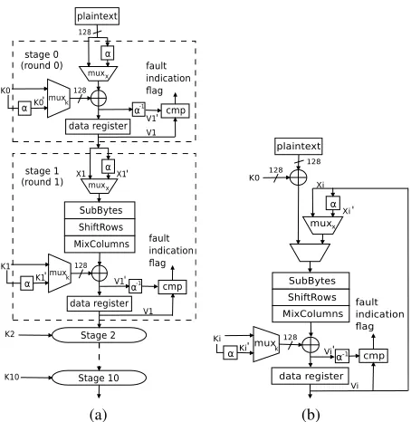
Fully pipelined: There are 11 stages in our pipelined architecture. For each pipeline stage in Fig. 4(a), we add two muxes (muxxandmuxk) and a comparator (cmp).αis a permutation of wires based on the invariance property.α−1is
the inverse permutation. We need two encryption cycles to detect the faults; let us call them C1 and C2. In C1, let the input and the key of round 1 beX1andK1. We run the encryption withmuxxandmuxk, selectingX1andK1as the inputs.
The round resultV1is stored in the data register. Then we run C2; we run the encryption withmuxxandmuxk, selecting
(a) (b)
Fig. 4: AES hardware architectures (a) Fully pipelined. (b) Iterative.cmpstands for comparator. We assume that the com-parator is fault tolerant.
cycle, and C2 is the corresponding extra cycle, which selects the permuted inputs to be performed after every C1. One can add several redundant C2 every encryption; we callRthe checking ratio which is the total number of rounds (10) divided by the number of redundant rounds.Rcan be changed based on the tradeoff between performance, reliability, and security specified by the designer. For a detailed analysis, please see Section 3.5.
Iterative: As shown in Fig. 4(b), we addmuxxandmuxkand a comparator. There is one security benefit of iterative
implementation. In an iterative architecture, each ciphertext takes 10 cycles to generate. The designer only needs to check specific rounds to enhance security and the details are discussed in Section 3.5. As long as the faults are detected before the ciphertext is generated, the faulty ciphertext will not be sent to the output. This will prevent an attacker from stealing the secret key. In the fully pipelined architecture, a ciphertext is generated every cycle. Therefore, if the faults are generated before the comparison, faulty outputs will be obtained by the attacker.
3.4 Fault Analysis
REPO detects all single-bit and single-byte faults. It is noted that single-byte fault is the most commonly used and practical fault model in fault attacks [35, 36]. Our simulations show that this CED technique detects 99.99999997% of multiple burst faults and 100% random faults. Fault coverage (FC) is calculated as:
F C= 1−F M R
where FMR is the fault miss rate calculated as:
F M R= Tundetected Ttotal−Tcorrect
whereTundetected is the number of tests in which faults are excited but not detected.Ttotal is the total number of tests
we applied.Tcorrect represents the tests in which the faults are not excited. Because single-bit fault is a special case of
single-byte fault, we are going to prove the 100% fault coverage for single-byte fault.
Proof. Case 1: A single-byte fault in S-box (SB). In Fig. 3, let theSBi,j(0 ≤i, j ≤3) have a single-byte fault. If the
SBs are implemented using ROMs, the considered fault corresponds to an address fault of the ROM, a fault in memory location, or a fault in the output data lines. If theSBs are implemented using combinational logic, the considered fault can appear in any gate of the implementation.
In C1, theSBi,j generates faulty outputyi,j. After ShiftRows, the outputs are[zr,c]r,c=0..3 =[yr,(r+c)mod4]r,c=0..3, and the faulty state element iszi,(j−i)mod4 = yi,j. In MixColumns, a single faulty input causes four bytes within
the same column to be faulty. The faulty state elements are represented as[ur,(j−i)mod4]r=0..3. After AddRoundKey, [vr,(j−i)mod4]r=0..3are the faulty state elements. In C2, we applyX
0
andK0as the permuted inputs. Using the same steps shown above, faulty state elements are represented as[vr,0(j−i)mod4]r=0..3. From (8), we know that
[v0r,(j−i)mod4]r=0..3= [vr,((j−i)+3mod4)mod4]r=0..3
[vr,c]3r,c=0=P−1([v
0
r,c]3r,c=0) =P−1([vr,(c+3)mod4]3r,c=0) (15)
Therefore, the faulty column in C1 is(j−i)mod4, but the faulty column in C2 corresponds to column((j−i)mod4) + 3)mod4in C1; note that0≤i, j≤3and(j−i)mod46= (((j−i)mod4) + 3)mod4.
Because faultySBi,j affects different columns in C1 and C2, we always compare a faulty column with a fault-free
column, and REPO detects the fault as long as it affects the output. Even if the fault does not affect the output of the check round, the outputs are still different. For a concrete example, letSB1,2be faulty, thus,y1,2is the faulty output byte. After ShiftRows,z1,1=y1,2. After MixColumns, the faulty state elements are shown as[ur,1]r=0..3. Then we apply this as the input of AddRoundKey, so faulty state elements are shown as[vr,1]r=0..3. Then we run C2, and faulty state elements are represented as[vr,01]r=0..3. Because[v
0
r,1]r=0..3= [vr,0]r=0..3, the faulty columns in C1 and C2 are different, and we detect the fault by comparing the outputs.
Case 2: A single-byte fault in ShiftRows. A fault in ShiftRows is equivalent to a fault at the input of MixColumns, because the ShiftRows on the FPGA and ASIC implementations are only wiring. Thus, we prove this in case 3.
Case 3: A single-byte fault in MixColumns. Because MixColumns is mainly implemented with XOR and a few other basic gates, we consider a fault in MixColumns in three scenarios: the input, the internal logic gates, and the output. If there is a fault in the input, the fault will propagate to all four bytes in the same column. Assuming that column[ur,j]r=0..3is faulty in C1, we know that the column[vr,j]r=0..3is faulty in the final output of the current round. In C2, we know that the column[u0r,j]r=0..3is faulty, and the column[v
0
r,j]r=0..3of the output of the round is also faulty. From (12) and (14), we know thatj0 = (j+ 3)mod4. Because the faulty columns of the two outputs are different, we detect the fault. If there is a fault in the output, we detect the fault because the fault will affect a different column in C1 and C2. If there is a fault in the internal gates, we also detect the fault. Because the circuits for the four columns are separate, the fault again will affect only one column in C1 and a different column in C2.
Case 4: A single-byte fault in AddRoundKey.AddRoundKey is mainly implemented as bit-wise XOR gates. We consider a fault in AddRoundKey as fault in the input or output. The fault at the input is equivalent to the fault in the output of MixColumns. Let us prove the theorem true for a single-byte fault at the output of AddRoundKey. Let the faulty byte be vi,jin the C1 andv
0
i,j in C2. From (14), we know thatv 0
i,j =vi,(j+3)mod4. Again, the faulty columns in C1 and C2 are different, and thus we detect the fault.
To achieve a 100% single-byte fault coverage, one needs hardware redundancy or hybrid redundancy [17], both of which have more than 100% hardware overhead. Our fault simulation confirms that REPO detects all single-bit and single-byte faults.
Fault Coverage for Multiple Byte Faults We simulated multiple byte faults for REPO and compared the fault coverage with the one proposed in [22]. These models cover both natural faults and fault attacks [7]. Due to technology constraints, an attacker may not be able to inject a single-bit fault [7]. Multiple byte faults are injected in the process. We use burst and random fault models [7].
0 1×10⁹ 2×10⁹ 3×10⁹ 4×10⁹ 5×10⁹ 6×10⁹ 7×10⁹ Number of burst faults injected
10-10 10-9 10-8 10-7 10-6 10-5 10-4 10-3 10-2 10-1
Fault miss rate
Parity for MixColumns and AddRoundKey Parity for SubBytes and ShiftRows REPO (α
1)
Fig. 5: Simulation results show that the fault miss rate of REPO is superior to that of the parity technique [22] with multiple byte burst fault model.
is determined by the LFSR. For each injection, the LFSR will generate 128 bit value, corresponding to 128 bit datapath in AES. If an LFSR bit value is 1, the simulator flips the corresponding AES bit. The location are determined by the random number generated from Boost C++ library [1].
The simulation results for burst faults are shown in Fig. 5. We compare our miss rate with [22]. This technique has two stages for their parity comparison. The first stage is parity for SubBytes and ShiftRows, and faults are injected only in the two operations. The second stage is parity for MixColumns and AddRoundKey, and similarly, faults are injected only in these two operations. REPO is implemented for the entire round. The dot-dash line respresents the fault miss rate of SubBytes and ShiftRows of [22]. The dash line represents the fault miss rate of MixColumns and AddRoundKey of [22]. The solid line represents the fault miss rate of REPO. We have injected up to7×109burst faults at the operation outputs and monitored detected faults. We count the number of faults being injected as shown in the x-axis in Fig. 5. For each fault injection, we run one AES round with104different test vectors. There are around108fault injections. All together, there are104×108 = 1012 tests. In around3×104 tests, REPO did not detect the faults. The fault coverage is1−3×10⁴
1012 = 99.99999997%. The fault miss rate for [22] is between10
−2 and10−3. The miss rate of our scheme is
between10−7and10−8; a reduction of105. The fault coverage of REPO will still be very high for each stage because each data are computed by different hardware units during the computation and recomputation.
Random faultsare injected at random locations, i.e., the 128-bit inputs or outputs of the operations. The size, location, and type of faults are determined by the random number generated from Boost C++ library [1]. In another simulation, we observe 100% fault coverage after injecting up to7×109random faults. The reason why the fault coverage is 100% is because the undetectable fault space is too small compared to the entire fault space. It is difficult to encounter such cases in the simulation. We discuss the undetectable fault in Section 5.2. Our fault model is similar to the one used in [7, 22]. In this model, faults occur in the input or output wires of each operation. Because the AES is implemented on the FPGA, in the physical fault model, the S-boxes are implemented as slice LUTs and registers are implemented as slice registers. Faults in slice LUTs and slice registers are equivalent to the ones in the output wires. ShiftRows only uses wires. Faults on the wire or the input/output of a gate are equivalent to faults in the input/output wire. AddRoundKey uses one level of gates. For MixColumns, we consider single fault and multiple byte faults in the input or output wires. Thus, the physical fault model matches the simulation fault model.
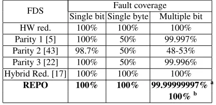
Table 1: Comparison of fault coverage. a. burst faults b. random faults
FDS Fault coverage
Single bit Single byte Multiple bit
HW red. 100% 100% 100%
Parity 1 [5] 100% 50% 99.997% Parity 2 [43] 98.7% 50% 48-53% Parity 3 [22] 100% 50% 99.996% Hybrid Red. [17] 100% 100% 100%
REPO 100% 100% 99.99999997%a 100%b
tradeoff between performance and detection latency can be explored by varying the checking ratioR, which is the ratio of the number of results computed without invariance to the number of results computed with REPO.
3.5 Security Analysis
We propose four CED checking policies that the designers can employ for their design depending on the implementation details as well as security and reliability requirements. They areSecurity without Decryption, Security with Decryption, Security without Decryption + Additional Reliability, and Security + Reliability.A technique called Randomized CED Round Insertion (RCRI) is also proposed to reduce the performance overhead while maintaining reliability.
Security without Decryption (REPO-S) Our investigation into all previous DFA shows that the attack is only able to utilize faults that are injected into the last four rounds, i.e, from the7thto10throunds. By injecting faults into the last four
rounds, the attacker is able to reduce the time to brute force the key dramatically, i.e., the brute force complexity will be in the range of28to232. However, if the attacker inject faults into other rounds, the brute force complexity will be2128 which is computationally infeasible to get the key with the current computer. Therefore, it is more secure to only check the last four rounds against a computationally bounded attacker. This will reduce the 100% performance overhead to 40%. The checking ratios in this case is 10/4 = 2.5.
Security with Decryption (REPO-SD) In the DFA community, the general assumption is that the attacker only needs to know the ciphertexts (faulty and fault-free). DFA is powerful because attacker does not need to know the plaintext. However, for some implementations, an attacker can access the decryption module, ask for decryption of arbitrary message, and obtain the decryption output. With this extra capability, attacker can inject faults in the first four rounds of the encryption, then ask the decryption unit to decrypt the faulty ciphertext and obtain a faulty plaintext. The effect is similar to injecting a fault in the last 4 rounds of decryption. Although the attacker inject faults in the encryption unit, the attacker can launch DFA for the decryption unit with the fault-free and faulty plaintexts. In this case, the first and last 4 rounds of the encryption and decryption all needs to be protected. Therefore, eight rounds needs to be protected. The checking ratio will be 10/8 = 1.25.
Security without Decryption + Additional Reliability (REPO-SAR) For reliability purposes, one still needs to check the first 6 rounds. Therefore, we propose RCRI.
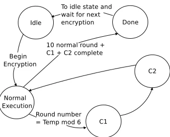
In RCRI, the positions of the CED rounds C1 and C2 are randomized during the 10 round AES encryption process for iterative architecture. The check round C2 is only inserted into the first 6 rounds. This can be implemented as shown in the state diagram of Fig. 6. A random number can be obtained using the randomness property of the AES algorithm.
Table 2: Comparisons of implementation of CED schemes on two Xilinx FPGAs. We use the metrics, FPGA platform, and results from [22]. Our pipeline implementation are shown in bold, and we implement the iterative architectures. a. the latency is 2x the original AES encryption/decryption b. using two (256×9) ditributed memories for CED of each S-box or inverse S-box c. using (256×9) distributed memories for CED of each S-box or inverse S-box d. checking ratio is 1 e. checking ratio is 2.5 f. checking ratio is 1.25 g. checking ratio is 2 h. This is implemented on xc2v1000 using an architecture with 4 S-boxes i. This is implemented in composite field with encryption and decryption sharing the logic. So the implementation numbers for the encryption and decryption are the same. j. The unit is K gates k. The unit is Kbps/gate
FPGA
Encryption Decryption
Arch. Scheme Slice Freq. Thro. Eff(Mbps Slice Freq. Thro. Eff.(Mbps (Model) (overhead) (MHz) (Gbps) /slice) (overhead) (MHz) (Gbps) /slice)
V
ir
tex
-4
(xc4vlx160-12)
Pipe.
Original 18335(-) 240.5 30.8 1.7 19322(-) 203.5 26.0 1.3 HW Red. 36684(100.1%) 240.5 30.8 1.1 38658(100.1%) 203.5 26.0 0.7 Parity 1 [5]b 39104(113.3%) 163.5 20.9 0.5 40244(108.3%) 145.4 18.6 0.5
Parity 2 [43]c 21211(15.7%) 240.5 30.8 1.4 22280(15.3%) 203.5 26.0 1.1
Parity 3 [22] 20127(9.8%) 240.5 30.8 1.5 20909(8.2%) 203.5 26.0 1.2 Hybrid 38273(108.7% [22]) 194.9 24.9a 0.6 38273(98.1% [22]) 194.9 24.9a 0.6
Red. [17] (1.6%) (1.6%)
REPO-SR 21253(15.9%) 232.3 14.9d 0.7d 22240(15.1%) 197.6 12.6d 0.6d
Iter.
Original 1905(-) 224.6 2.9 1.5 2002(-) 192.0 2.5 1.2 REPO-S 2156(13.2%) 217.4 2e 0.9e 2253(12.5%) 186.7 1.7e 0.8e REPO-SD 2161(13.4%) 217.4 1.6f 0.7f 2258(12.9%) 186.7 1.3f 0.6f REPO-SAR 2170(13.9%) 217.4 1.9g 0.9g 2267(13.2%) 186.7 1.6g 0.8g REPO-SR 2154(13.1%) 217.4 1.4d 0.7d 2251(12.4%) 186.7 1.2d 0.5d
V irtex-II Pipe.h RESO [8] (2.7%/-2.4%) - - -
-90nm ASIC Iter.i Hybird [39] 16.1K (24.8%)j 362.32 2.21 137.18k 16.1K (24.8%)j 362.32 2.21 137.18k
V
ir
tex
-5
(xc5vlx110-3)
Pipe.
Original 2960(-) 371.7 47.6 16.1 3906(-) 296.3 37.9 9.7 HW Red. 5934(100.5%) 371.7 47.6 10.2 7826(100.4%) 296.3 37.9 5.5
RESO [8] (2.7%/-2.4%) - - -
-Parity 1 [5]b 5590(88.9%) 282.8 36.2 6.5 6680(71.2%) 260.2 33.3 4.9 Parity 2 [43]c 3619(22.3%) 304.0 38.9 10.7 4426(13.3%) 277.0 35.5 8.0 Parity 3 [22] 3757(26.9%) 371.7 47.6 12.7 4286(9.7%) 296.3 37.9 8.8 Hybrid 5849(97.6% [22]) 284.4 36.4a 6.2 5849(49.7% [22]) 284.4 36.4 6.2
Red. [17] (-14.8%) (-14.8%)
REPO-SR 3664(23.9%) 358.9 23.0d 6.6d 4434(13.5%) 288.9 18.5d 4.2d
Iter.
Original 344(-) 347.0 4.4 12.8 462(-) 286.4 3.7 7.9
REPO-S 433(25.9%) 335.8 3.1e 7.2e 534(15.6%) 273.1 2.6e 4.9e
REPO-SD 434(26.2%) 335.8 2.4f 5.6f 535(15.8%) 273.1 2.0f 3.7f
REPO-SAR 438(27.3%) 335.8 2.9g 5.9g 539(16.7%) 273.1 2.4g 4.9g
REPO-SR 432(25.6%) 335.8 2.2d 5.1d 533(15.4%) 273.1 1.8d 3.4d
V irtex-II Pipe.h RESO [8] (2.7%/-2.4%) - - - - - -
Fig. 6: State machine for RCRI
CED round are complete. For the mod operation, we can take the last 4 bits of Temp and apply it to a lookup table which contains modulo 6 results from input 0 to 15. For the pipeline architecture, this method creates unbalance load between pipeline stages. Therefore, we insert the check round after every normal round.
IfR= 1, all rounds are checked. The fault miss rate will remain the same for permanent and transient faults. IfR >1 (R≤5), everyRthresult will be checked. Let us assume the transient faults appear forNcycles. WhenR≤N, the fault coverage remains the same, because the results of C1 and C2 are checked before the faults disappear. WhenR > N, the probability of detecting a single-bit and single-byte fault isNR×100%and that of multiple burst faults isNR×99.99999997%. For normal reliability requirement, adding one check round yields a checking ratio of 10/5 = 2.
Security + Reliability (REPO-SR) If the reliability requirement is very high, the designer can check all the rounds. In this case the checking ratio is 10/10 = 1.
3.6 Implementation and Comparison
The implementation results shown in Table 2 are all post place-and-route. We implement fully pipelined and iterative ar-chitectures. We use pipelined distributed memories for S-boxes and inverse S-boxes similar to [22]. Hardware redundancy, information redundancy [5, 22, 43], hybrid redundancy [17], and REPO are compared. The metrics include (1) slice utiliza-tion (the number of occupied slices), (2) slice overhead (ratio of number of slices for CED schemes over the number of slices for AES), (3) maximum clock frequency, (4) throughput, and (5) efficiency (ratio of (4) over (1)).
2 5 10 15 20 25 30 Number of faulty bits
10-8 10-7 10-6 10-5 10-4 10-3 10-2
Fault miss rate
Invariance α
1, α3
Invariance α 2
Fig. 7: Fault miss rate for invarianceα1,α2, andα3
utilization of encryption and decryption. However, the efficiency of REPO-SR is higher than that of [17]. Most importantly, REPO-SR and all other CEDs do not require both encryption and decryption to be on chip. The RESO technique in [8] is implemented on Virtex-II FPGA. It has 2.7% additional flips flops (2023 against 1969), but 2.4% less slices (1699 against 1740) compared to no CED. Although the hardware overhead is quite small, this technique only focuses on fault detection in S-boxes. For iterative architecture, because round 0 is performed in the same clock cycle as round 1, an extra delay is added in the critical path. The designer can specify four different checking policies, i.e., REPO-S, REPO-SD, REPO-SAR, and REPO-SR. REPO-SR has the least hardware overhead because it does not need extra state registers and decoders. The hardware overhead of REPO as a 15.4-27.3% is slightly higher than that of the pipeline architecture on Virtex-5. If REPO is implemented in ASIC, it needs an extra metal layer for routing, so thatα(or α−1) will not overlap with the original datapath. This observation also applies to RESO. Another hybrid redundancy technique in [39] is implemented using 90nm CMOS ASIC library. The compact implementations achieved performances of 2.21 Gbps with 16.1 Kgates. In contrast, the performances without CED are 1.66 Gbps with 12.9 Kgates. The performance increase are due to sub-pipelining. The hardware savings of this technique come from the resource sharing between the encryption and decryption. Therefore, although over 100% hardware overhead is expected for both encryption and decryption unit, the sharing reduce the hardware overhead to only 24.8%.
3.7 Evaluation of Round Level Invariances
There are other invariances that can be used for CED [20]. Most of them restrict the pattern of the inputs and thus are not effective when realistic random inputs are provided. However, there are two other invariances that allow us to perform CED on any inputs:
α2(X) =
x0,2x0,3x0,0x0,1 x1,2x1,3x1,0x1,1 x2,2x2,3x2,0x2,1 x3,2x3,3x3,0x3,1
(16)
α3=α1(αpre(X)) =α1(
x0,0x0,3x0,2x0,1 x1,0x1,3x1,2x1,1 x2,0x2,3x2,2x2,1 x3,0x3,3x3,2x3,1
) (17)
α2swaps the first and third columns and also the second and fourth columns in the state matrix.α3 is the same as α1 except that the initial inputX is permuted byαprebefore being applied to the input. Fault miss rate for CED using
invariancesα1,α2, andα3are compared in Fig. 7. In our experiment, we gradually increase the number of faulty bits from two to 30. We have done104fault injections for each fixed number of faulty bits. In each fault injection, a fix number of faults is injected, e.g., 11 faults. For each injection, we applied109 test vectors. The fault miss rate dropped sharply to below10−7after we injected 11 faults usingα
Fig. 8: Grøstl-256 algorithm [12].
was very low and thus not shown in Fig. 7. The fault miss rates of invarianceα1andα3are lower than the fault miss rate of invarianceα2with any number of faults injected. Compare toα2, the area and performance overheads ofα1are the same. Forα3, one first need to applyαpre(X)as input to run C1, and store the resultVpre. Then useα1(αpre(X))as input to run
C2, and applyα−11to the resultVpre0 to compare withVpre. Both C1 and C2 are extra overhead for performance. Compare
withα3, C2 is the only performance overhead forα1. Therefore,α1is the most effective invariance.
There are several other invariances that can also be used for CED in AES. However, these invariances are not applicable to all the round operations. Rather, they are applicable to a subset of the round operations. We discuss this in Section 5.1.
4
REPO for AES-style Primitives
AES is the standardized symmetric key algorithm and it is the most widely used symmetric key algorithm. REPO is also applicable to many AES-like structures such as Khazad, Anubis, Whirlpool, Grindahl, Grøstl, LANE, and SHAvite-3. By giving a discussion on AES and Grøstl, it will benefit many other algorithms.
4.1 Grøstl Algorithm
Grøstl hash function is capable of returning digests of any number of bytes from 1 to 64; i.e., from 8 to 512 bits in 8-bit steps. The variant returning n 8-bits is called Grøstl-n. In this paper, we consider Grøstl-256 for brevity, but the same technique can also be used for other digest sizes.
Grøstl-256 takes an arbitrary length message and generates a 256-bit digest as shown in Fig. 8. Let us denote the message to be hashed asM. This message is first padded and then split into 512-bit message blocks. We denote these blocks bymi (1 ≤ i ≤ t). Grøstl-256 has one or more compression function f and a truncate function Ω. Function
f compresses two 512-bit inputs (ht−1 andmt) to obtain one 512-bit output (ht). One first chooses an initial value for
the chaining inputh0. Each intermediate function generates output according tohi=f(hi−1, mi). When the last message
block is processed,htis generated. Then, an output transformationΩtakes the 512-bit output from functionfand truncates
it into 256 bits to generate the final digest.
4.2 Compression Function
As shown in Fig. 8,f is constructed from two permutations, P, and Q, such thatf(hi−1, mi) =P(hi−1+mi) +Q(mi) +
hi−1, where hi−1 andmi are the chaining input, and message block, respectively. P and Q are both inspired by AES
round operations; thus, their structures are similar to AES. P and Q both contain multiple rounds, and 10 rounds are used for Grøstl-256. One permutation round consists of AddRoundConstant, SubBytes, ShiftBytes, and MixBytes, denoted by Ag,Bg,Sg, andMg, respectively. It is noted that the only two differences between P and Q are the constant values in
AddRoundConstant and the position shifts in ShiftBytes. The input of each operation acts on a 512-bit input state where each state element is a byte inGF(28). In this paper, each byte is denoted bysr,c(0 ≤r, c≤7), and indicates that this
byte is in rowrand columncin state matrix.
S = [sr,c]r,c=0..7 (18)
In AddRoundConstant, the input state is added (modulo-2) to the round-dependent constant matrixD[j]. Let X be the input and the resulting output is:
whereD[j]is the round constant used in round j. P and Q have different round constant matrices. It is noted that in permutation P, all the bytes of the round constants are zero, except for the first row, which contains byte constants that depend on roundj. The elements of the first row are:
[d[j]1,c]c=0..7=c0⊕j (20)
wherecis the column number. Similarly, in Q, all the bytes in the round constant matrices are 0xff, except for the last row which has round-dependent constants. The elements of the last row are:
[d[j]7,c]7,c=0..7= (f −c)f⊕j (21)
In SubBytes, all the bytes are processed separately by 64 SBs. Each SB is the same as the ones in AES. The resulting output is:
Z=Bg(Y) = [yr,c]r,c=0..7 (22)
In ShiftBytes of P, the rows of the state are shifted cyclically byte-wise using a different offset for each row. The eight rows from row 0 to 7 are cyclically shifted to the left bykbytes, wherekis the number of the row. The resulting output is:
U =Sg(Z) = [zr,(r+c)mod8]r,c=0..7= [ur,c]r,c=0..7 (23)
In ShiftBytes ofQ, the number of bytes shifted are:
f(r) =
2×r+ 1 0≤r≤3
(2×r)mod8 4≤r≤7 (24)
The resulting output is:
U =Sg(Z) = [zr,(c+f(r))mod8]r,c=0..7= [ur,c]r,c=0..7 (25)
In MixBytes, the output state is obtained by multiplying a constant matrix N with the output of ShiftBytes. N is shown below:
02 02 03 04 05 03 05 07 07 02 02 03 04 05 03 05 05 07 02 02 03 04 05 03 03 05 07 02 02 03 04 05 05 03 05 07 02 02 03 05 04 05 03 05 07 02 02 03 03 04 05 03 05 07 02 02 02 03 04 05 03 05 07 02
The resulting output of P is:
V =Mg(U) = [vr,c]r,c=0..7 (26)
The resulting output of Q is:
V =Mg(U) = [vr,c]r,c=0..7 (27)
Finally, the functionΩdiscards all but the trailing 256 bits ofP(ht) +ht, wherehtis the 512-bit output of the last
functionf. The details of permutation P have been presented earlier in this subsection.
4.3 Invariance of Grøstl
We discover that a mapping invariance similar to AES also holds true for P and Q in Grøstl. Because the proof for this invariance is similar to the one for AES, we state the theorem without giving a formal proof.
Theorem 3. A round in permutation P is represented as
Fig. 9: REPO architecture 1 for Grøstl.
Fig. 10: REPO architecture 2 for Grøstl.
where X is the 512-bit input to the round. Byte permutationβexists such that the following holds true:
Mg(Sg(Bg(Ag(D[j])(X)))) =
β−1(Mg(Sg(Bg(Ag(β(D[j]))(β(X)))))) (28)
whereβ−1denotes the inverse function ofβ. One of the byte permutations is:
β(X) =β([xr,c]r,c=0..7) = [xr,(c+7)mod8]r,c=0..7
β−1([xr,(c+7)mod8]r,c=0..7) = [xr,c]r,c=0..7 (29)
4.4 REPO for Grøstl
We propose two REPO architectures for Grøstl as shown in Figs. 9 and 10.
REPO architecture 1: The permutation is done at the input of the compression function. The output is inverse permuted and compared with the previous output from the compression function. The CED round can either be the first round in the ten round compression function, or it can be an extra ten round compression in the entire hash execution. This REPO architecture uses four muxes and one comparator.
2 5 10 15 Number of faults injected
10-8 10-7 10-6 10-5 10-4 10-3
Fault miss rate
1 2 3 4
Fig. 11: Fault miss rate for P with different amount of permutation.
2 5 10 15
Number of faults injected 10-8
10-7 10-6 10-5 10-4 10-3
Fault miss rate
1 2 3 4
Fig. 12: Fault miss rate for Q with different amount of permutation.
4.5 Fault Analysis
Single-Bit and Single-Byte faults REPO also detects all single-bit and single-byte faults for Grøstl. The proof is similar to that of theorem 2.
Fault Coverage for Multiple Faults We have simulated different numbers of faults in P and Q from 2 to 30. For each number of faults, we apply5×108test vectors in the simulations. The fault miss rates in the presence of different numbers of faults for P and Q are shown in Figs. 11 and 12, respectively. The number of permuted bytes is from one to four. The simulation results show that in both cases, the fault miss rate decreases to below10−8after we inject 13 faults. The results also shows the fault coverage with respect to the number of different amount of byte permuted. The fault coverage does not diverge significantly. The variation in both figures is because the random number generator we use is not perfectly random.
4.6 Implementation Results
As shown in Table 3, we have implemented Grøstl and two CED architectures. The Grøstl merges functionΩ within functionf to achieve compact implementation. Both REPO architectures decrease the frequency of Grøstl because of the extra gates added in the critical paths. The throughputs of REPO decreases because of the extra CED rounds. In REPO architecture 2, when the checking ratio is 10 and 1, the throughput is 2.08Gbps and 1.14Gbps, respectively.
4.7 Grøstl Invariances
Fix points invariance [12]:One choosesmarbitrarily, then we have the following relationship:
h=P−1(Q(m))⊕m⇒f(h, m) =h
Table 3: Comparisons of implementation of REPO for Grøstl on Xilinx Virtex-5 FPGA (xc5vlx110-3). a. checking ratio is 10 b. checking ratio is 1
Scheme Slice(overhead) Freq. Thro. Eff.(Mbps (MHz) (Gbps) /slice) Grøstl 3091(-) 191.3 2.45 0.79 REPO 1 3354(8.5%) 175.7 2.23 0.67 REPO 2 3720(20.3%) 178.4 2.08a– 1.14b 0.56
Table 4: Comparison of time redundancy techniques for AES. B is SubBytes. S is ShiftRows. M is MixColumns. A is AddRoundKey. X means any input pattern.∆means restricted pattern.
Time Transient Fault Permanent Fault DFA Redundancy B S M A B S M A Simple [24](X) √ √ √ √
DDR [23](X) √ √ √ √ General RESO √ √ √ √ √
[8](X)
(B(X))277182 √
M(S(X))8 √ √
A(M(X))8 √ √
M(S(B(∆))) √ √ √
(M(S(B(∆))))2 √ √ √
(M(S(B(∆))))4 √ √ √
REPO(X) √ √ √ √ √ √ √ √ √
requires extra hardware. Alternatively, one can precompute many pairs ofhand stores them along with their associatedm on the chip. This can be use as a built-in-self-test (BIST), however, BIST requires extra memories and other logics.
Preimage invariance [12]:For a given targetT,MandXexist such that:
T =H+P(H+M) +Q(M) =X+P(X) +M +Q(M)
Note thatH =X+M.
To computeM and X, one needs to use cycle finding algorithm, so it is not applicable at runtime. One can also precompute many pairs ofM andX and use BIST technique for fault detection. As mentioned previous, this is costly compared with the invariance-based scheme.
5
Discussion
In this section, we compare REPO with other time redundancy techniques. We also point out its limitations.
5.1 Compared with Time Redundancy for AES
In this section, we analyze the advantage and disadvantage of each of different time redundancy technique in Table 4. At a first glance, REPO looks very similar to simple time redundancy but requires some more hardware. However, simple time redundancy cannot detect permanent faults and long transient faults that last for the normal computation and recomputation. REPO can detect both transient and permanent faults because the hardware computing the same data byte are different in the computation and recomputation. The DDR technique [23] is a form of time redundancy. Attackers have successfully injected long transient faults to break this countermeasure [8]. Moreover, our technique is a complementary technique with the DDR technique. A person who employs our technique can also add DDR to it and vice versa.
(a) (b)
Fig. 13: A case when two stuck-at faults are not detected
Invariance(B(X))277182: If you apply an initial input and feed the output back to the input of S-box for 277182 times, the S-box output will be the same as the initial input. If one uses this invariance for CED, the chip needs to stop the normal computation and switch to CED mode. In the CED mode, it will run 277182 cycles to compare the output with the original input, which incurs huge performance overhead. It will not detect transient fault when the chip is not operating in the CED mode. Moreover, this invariance only protects the SubBytes operation.
InvarianceM(S(X))8andA(M(X))8: These invariances has similar drawbacks as the previous invariance. As shown in Table IV, they only protect some round operations and they cannot detect transient faults if AES is not in CED mode.
InvarianceM(S(B(∆))),(M(S(B(∆))))2, and(M(S(B(∆))))4: These invariances have restrictions on input pat-terns. Letw, x, y, z, s, t, u, v ∈ GF(28).α
4 = (x, x, ..., x). From this invariance, we know that if all input bytes are the same, the output bytes are also the same. Because it is unlikely that all the input bytes are the same, to use this invariance, we can also use the same hardware but we extend the first input bytes to the rest of the bytes. In the check round, we select this input. The hardware is the same as invarianceα1. If S-boxes are implemented using memory, there is a significant drawback of this technique. For one test vector, it tests only one memory location. Therefore, the fault coverage for S-box is only around 1/256. There are several other invariances similar toα4. Interested readers can find more information in [20]. Another problem is that it cannot detect transient fault if the AES is not in test mode.
Because DFA can utilize faults injected in the targeted round and it is not limited to faults injected in a specific round operation, all the round operations need to be protected. Even if all the rounds are protected, it is still not enough to defend against DFA. As demonstrated in [8], the attacker can inject faults that last for both the computation and recomputation to defeat the DDR technique. The general RESO technique detects permanent faults in ShiftRows, but not permanent faults in the other three round operations. REPO detects permanent faults in all four round operations.
5.2 Undetectable Faults
(a) (b)
Fig. 14: A case when four bit flip faults are not detected
special case, REPO cannot detect the faults. However, the assumption of this attacker is really strong, it is not clear how the attacker can achieve this by the current fault injection technology.
5.3 Limitations
We would like to point out that REPO does rely on the redundant hardware structure in the circuit. Let’s take a look at the S-boxes in AES. To detect faults in S-boxes, the same data bytes need to be computed on different S-boxes in the normal round and the check round.
Therefore, in AES implementations with 32-bit datapath [38] [25] [10], REPO will not be as effective. Because the data will be computed by the same hardware in the normal and the check round, REPO will have the same fault detection capability as time redundancy. Similarly, REPO is the same as time redundancy in AES implementations with 8-bit datapath [14]. In those implementations, we recommend the designers to use full hardware redundancy or hybrid redundancy.
6
Conclusion
As fabrication technologies advance, reliability has become a significant challenge for hardware designers. Moreover, fault attacks show the occurrence of errors must be considered seriously in secure implementations. Error detections schemes can improve the security of cryptographic implementations.
In this work, we propose REPO for AES and AES-style hash function Grøstl. The fault coverage for both AES and Grøstl are 100% for single-bit and single-byte faults, and close to 100% for multiple-bit burst faults and random faults. The hardware overheads is around 12.4-27.3% for AES and 8.5-20.3% for Grøstl. REPO relies on the algorithmic property of AES round invariances, thus, it is applicable to many AES-style cryptographic primitives including stream ciphers and other cryptographic hash functions. Although we implement REPO based on AES-128, it can also be applied to AES with other key lengths such as 192 and 256.
Moreover, AES-style structure is made of very simple and fast operations that can reach very fast hardware implemen-tation. For cryptographic circuits embedded in a larger system as a coprocessor, the cryptographic hardware is likely to work a lower frequency than its maximum capacity. Thus, a large portion of the clock cycle would be wasted. In this case, one can combine REPO with DDR approach to improve performance. Therefore, even when the checking ratio is one, the error detection capabilities incurs a very low cost. The control unit needs to be protected as well. We suggest protecting the control unit with state validation, transition verification, and duplication of selected components.
Acknowledgement
The authors would like to thank the reviewers for their valuable comments. This material is based upon work supported by the NSF CNS program under grant 0831349.
References
1. Boost C++ Libraries. http://www.boost.org/.
3. Michel Agoyan, Jean-Max Dutertre, David Naccache, Bruno Robisson, and Assia Tria. When Clocks Fail: On Critical Paths and Clock Faults. InCARDIS, pages 182–193, 2010.
4. Alessandro Barenghi, Cédric Hocquet, David Bol, François-Xaiver Standaert, Francesco Regazzoni, and Israel Koren. Exploring the Feasibility of Low Cost Fault Injection Attacks on Sub-Threshold Devices through An Example of A 65nm AES Implementation. pages 48–60. in Proc. Workshop RFID Security Privacy, 2011.
5. Guido Bertoni, Luca Breveglieri, Israel Koren, Paolo Maistri, and Vincenzo Piuri. Error Analysis and Detection Procedures for a Hardware Implementation of the Advanced Encryption Standard.IEEE Trans. Computers, 52(4):492–505, 2003.
6. S. Borkar. Designing Reliable Systems from Unreliable Components: the Challenges of Transistor Variability and Degradation.
MICRO, 25(6):10–16, 2005.
7. Luca Breveglieri, Israel Koren, and Paolo Maistri. An Operation-Centered Approach to Fault Detection in Symmetric Cryptography Ciphers.IEEE Trans. Computers, 56:635–649, May 2007.
8. G. Canivet, P. Maistri, R. Leveugle, J. Clédière, F. Valette, and M. Renaudin. Glitch and Laser Fault Attacks onto a Secure AES Implementation on a SRAM-Based FPGA.Journal of Cryptology, 24, 2011.
9. Y. Chih-Hsu and W. Bing-Fei. Simple Error Detection Methods for Hardware Implementation of Advanced Encryption Standard.
IEEE Trans. Computers, 55(6):730–731, 2006.
10. Pawel Chodowiec and Kris Gaj. Very Compact FPGA Implementation of the AES Algorithm. InCHES, pages 319–333, 2003. 11. W. Fischer and C.A. Reuter. Differential Fault Analysis on Grøstl. InFDTC, pages 44–54, Sept. 2012.
12. P. Gauravaram, L. R. Knudsen, K. Matusiewicz, F. Mendel, C. Rechberger, M. Schläffer, and S. S. Thomsen. Grøstl-A SHA-3 Candidate. http://www.groestl.info/Groestl.pdf, 2011.
13. Christophe Giraud. DFA on AES. InAES, pages 27–41, 2005.
14. Tim Good and Mohammed Benaissa. AES on FPGA from the Fastest to the Smallest. InCHES, pages 427–440, 2005.
15. Xiaofei Guo and R. Karri. Invariance-based Concurrent Error Detection for Advanced Encryption Standard. InDAC, pages 573–578, Jun 2012.
16. Mark Karpovsky, Konrad J. Kulikowski, and Alexander Taubin. Robust Protection Against Fault-Injection Attacks of Smart Cards Implementing the Advanced Encryption Standard. InDNS, pages 93–101, 2004.
17. Ramesh Karri, Kaijie Wu, P. Mishra, and Y. Kim. Concurrent Error Detection Schemes of Fault Based Side-Channel Cryptanalysis of Symmetric Block Ciphers.IEEE Trans. Computer-Aided Design, 21(12):1509–1517, Dec 2002.
18. Farouk Khelil, Mohamed Hamdi, Sylvain Guilley, Jean Luc Danger, and Nidhal Selmane. Fault Analysis Attack on an AES FPGA Implementation. InNTMS, pages 1–5, 2008.
19. Konrad J. Kulikowski, Mark G. Karpovsky, and Alexander Taubin. Robust codes and robust, fault-tolerant architectures of the advanced encryption standard.Journal of System Architecture, 53(2-3):139–149, feb 2007.
20. Tri Van Le, Rudiger Sparr, Ralph Wernsdorf, and Yvo Desmedt. Complementation-Like and Cyclic Properties of AES Round Functions. InAES, pages 128–141, 2005.
21. V. Lomne, T. Roche, and A. Thillard. On the Need of Randomness in Fault Attack Countermeasures - Application to AES. In
FDTC, pages 85–94, Sept. 2012.
22. M. Mozaffari-Kermani and A. Reyhani-Masoleh. Concurrent Structure-Independent Fault Detection Schemes for the Advanced Encryption Standard.IEEE Trans. Computers, 59(5):608–622, 2010.
23. P. Maistri and R. Leveugle. Double-Data-Rate Computation as a Countermeasure against Fault Analysis.IEEE Trans. Computers, 57(11):1528–1539, Nov 2008.
24. T.G. Malkin, F.-X. Standaert, and Moti Yung. A Comparative Cost/Security Analysis of Fault Attack Countermeasures. InFDTC, pages 109–123, Sept 2005.
25. Scott McMillan and Cameron Patterson. JBitsTM Implementations of the Advanced Encryption Standard (Rijndael). InFPL, pages 162–171, 2001.
26. Alfred J. Menezes, Paul C. van Oorschot, and Scott A. Vanstone. Handbook of Applied Cryptography.CRC Press, 1996.
27. Amir Moradi, Mohammad T. Manzuri Shalmani, and Mahmoud Salmasizadeh. A Generalized Method of Differential Fault Attack against AES Cryptosystem. InCHES, pages 91–100, 2006.
28. Mehran Mozaffari-Kermani and Arash Reyhani-Masoleh. A Lightweight High-Performance Fault Detection Scheme for the Ad-vanced Encryption Standard Using Composite Field.IEEE Trans. VLSI Systems, 19(1):85–91, 2011.
29. Mehran Mozaffari-Kermani and Arash Reyhani-Masoleh. Reliable Hardware Architectures for the Third-Round SHA-3 Finalist Grøstl Benchmarked on FPGA Platform. InDFT, pages 325–331, Oct 2011.
30. S. S. Mukherjee, J. Emer, and S. K. Reinhardt. The Soft Error Problem: An Architectural Perspective. InHPCA, pages 243–247, 2005.
31. Debdeep Mukhopadhyay. An Improved Fault Based Attack of the Advanced Encryption Standard. InAFRICACRYPT, pages 421–434, 2009.
33. National Institute of Stardards and Technology (NIST). Advanced Encryption Standard (AES). http://csrc.nist.gov/publications/ fips/fips197/fips-197.pdf, Nov 2001.
34. National Institute of Stardards and Technology (NIST) Federal Information Processing Standards (FIPS) publication 140-2. Security requirements for cryptographic modules. http://csrc.nist.gov/publications/fips/fips140-2/fips1402.pdf, Mar 2001.
35. G. Letourneux P. Dusart and O. Vivolo. Differential Fault Analysis on AES. InCryptology ePrint Archive, 2003.
36. G. Piret and J.J. Quisquater. A Differential Fault Attack Technique against SPN Structures, with Application to the AES and Khazad. InCHES, pages 77–88, Sept 2003.
37. J. Rajendran, H. Borad, S. Mantravadi, and R. Karri. SLICED: Slide-based Concurrent Error Detection Technique for Symmetric Block Cipher. InHOST, pages 70–75, Jul 2010.
38. Akashi Satoh, Sumio Morioka, Kohji Takano, and Seiji Munetoh. A Compact Rijndael Hardware Architecture with S-Box Opti-mization. InASIACRYPT, pages 239–254, 2001.
39. Akashi Satoh, Takeshi Sugawara, Naofumi Homma, and Takafumi Aoki. High-Performance Concurrent Error Detection Scheme for AES Hardware. InCHES, pages 100–112, Aug 2008.
40. Nidhal Selmane, Sylvain Guilley, and Jean-Luc Danger. Practical Setup Time Violation Attacks on AES. pages 91–96. EDCC, 2008.
41. Daniel P. Siewiorek and Robert S. Swarz. Reliable Computer Systems: Design and Evaluation. A K Peters/CRC Press; 3 edition, 1998.
42. Michael Tunstall, Debdeep Mukhopadhyay, and Subidh Ali. Differential Fault Analysis of the Advanced Encryption Standard Using a Single Fault. InWISTP, pages 224–233, 2011.
![Fig. 5: Simulation results show that the fault miss rate of REPO is superior to that of the parity technique [22] with multiplebyte burst fault model.](https://thumb-us.123doks.com/thumbv2/123dok_us/7900983.1311572/9.612.200.415.83.243/simulation-results-fault-repo-superior-parity-technique-multiplebyte.webp)
![Table 2: Comparisons of implementation of CED schemes on two Xilinx FPGAs. We use the metrics, FPGA platform, andresults from [22]](https://thumb-us.123doks.com/thumbv2/123dok_us/7900983.1311572/11.612.79.534.241.656/table-comparisons-implementation-schemes-xilinx-metrics-platform-andresults.webp)

![Fig. 8: Grøstl-256 algorithm [12].](https://thumb-us.123doks.com/thumbv2/123dok_us/7900983.1311572/14.612.199.416.86.160/fig-grostl-algorithm.webp)
