Design of Inverters with Harmonics Reduction Technique
Using Artificial Neural Network.
Sisir MazumderP
1
P
, Susovan DuttaP
2
P
and Akash SamantaP
3
P
P
1
P
Asstt.Professor , Department of Electrical Engineering, Gurunanak Institute of Technology, Kolkata-700114, West Bengal, India.
P
2
P
Asstt.Professor, Department of Electrical Engineering, Gurunanak Institute of Technology, Kolkata-700114, West Bengal, India
P
3
P
Student, Department of Electrical Engineering, Gurunanak Institute of Technology, Kolkata-700114, West Bengal, India.
Abstract
Now a days power interruption is a burning problem so we have to save energy to reduce the energy crisis and to solve the problem of interruption i.e., to get 1Tuninterruptible
power supply we need inverter. Also in those places where electrical infrastructure is not well developed i.e., the villages of Africa, Australia where reliable power severally limited there we can get useful power to fulfill the most essential power like to drive medical instrument etc by inverter technology .but to utilize those power for such sensitive instrument we have pure sine wave power supply from a dc source so harmonic reduction is necessary.
Keywords:Grid tie inverter, PWM, ANN, BPA.
1T
1. Introduction
1T
This report focuses on DC to AC power inverters which aim to efficiently transform DC power source to high village AC source, similar to power that available at the wall outlet. The conventional method of power transmission is direct current(short distance) & for long distance transmission alternating current method is preferred, since the voltage can be easily step up using transformer so resistive loss is reduced. Besides those reason the AC power also very important as most of electrical devices are made for AC power. Also ther1Te are
several advantages of AC supply. However AC supply is not always available and the need for mobility and simplicity has given batteries an advantage in portable power. Thus for portable ac power inverter are needed. Also in those places where the electrical infrastructure is not well developed, in those places to get uninterruptible1T
power supply1T inverter plays an important role. In
those places to run medical instrument or small
household device we need portable AC power which can come from DC batteries charged using solar panels. But the medical instruments are very sensitive so to run those we have to filter the harmonics from inverter output. Our paper covers that part also. 1.1 Basic inverter
An0T0Tinverter0T0Tis an electrical device that converts0T0Tdirect
current0T0T(DC) to0T0Talternating current0T0T(AC); the
converted AC can be at any required voltage and frequency with the use of appropriate0T0Ttransformers,
switching, and control circuits. Solid-state inverters have no moving parts and are used in a wide range of applications, from small0T0Tswitching power supplies0T0Tin
computers, to large0T0Telectric utility0T0Thigh-voltage direct
current0T0Tapplications that transport bulk power.
Inverters are commonly used to supply AC power from DC sources such as0T0Tsolar panels0T0Tor0T0Tbatteries.
1.2 Types
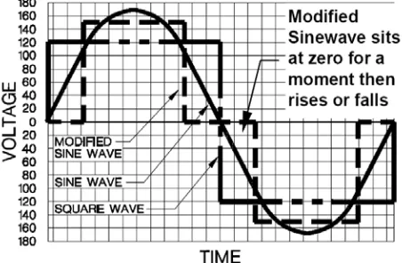
1.2.1 Modified sine wave
The output of a modified sine wave inverter is similar to a square wave output except that the output goes to zero volts for a time before switching positive or negative. It is is compatible with most electronic devices, except for sensitive or specialized equipment, for example certain laser printers, fluorescent lighting, audio equipment. Most AC motors will run off this power source albeit at a reduction in efficiency of approximately 20.
1.2.2 Pure sine wave
A pure sine wave inverter produces a nearly perfect sine wave output (<3% total harmonic distortion) that is essentially the same as utility-supplied grid power. Thus it is compatible with all AC electronic devices. This is the type used in grid-tie inverters. Its design is more complex, and costs more per unit powerP
.
P
The electrical inverter is a high-power electronic oscillator. It is so named because early mechanical AC to DC converters was made to work in reverse, and thus was "inverted", to convert DC to AC. 1.2.3 Grid tie inverter
A grid tie inverter is a sine wave inverter designed to inject electricity into the electric power distribution system. Such inverters must synchronise with the frequency of the grid. They usually contain one or more Maximum power point tracking features to extract the maximum amount of power, and also include safety features.
Advanced designs
Figure 1: H-bridge inverter circuit with transistor switches and antiparallel diodes
There are many different power circuit topologies and control strategies used in inverter designs. Different design approaches address various issues that may be more or less important depending on the way that the inverter is intended to be used.
The issue of waveform quality can be addressed in many ways. Capacitors and inductors can be used to filter the waveform. If the design includes a transformer, filtering can be applied to the primary or the secondary side of the transformer or to both sides. Low-pass filters are applied to allow the fundamental component of the waveform to pass to the output while limiting the passage of the harmonic components. If the inverter is designed to provide power at a fixed frequency, a resonant filter can be used. For an adjustable frequency inverter, the filter must be tuned to a frequency that is above the maximum fundamental frequency.
Since most loads contain inductance, feedback rectifiers or antiparallel diodes are often connected across each semiconductor switch to provide a path for the peak inductive load current when the switch is turned off. The antiparallel diodes are somewhat similar to the freewheeling diodes used in AC/DC converter circuits.
1.3 Pure sine wave inverter & its necessity
In the previous section we saw that how can we get AC power from a dc source but in that case the inverter output wave is not pure sine wave so in latter section we shall come to know why a pure sine wave inverter is necessary through a comparative study. In the market there are two different types of power inverters are available, modified sine wave and pure sine wave generators. These inverters differ in their outputs, providing varying levels of efficiency and distortion that can affect electronic devices in different ways. A modified sine wave is similar to a square wave but instead has a “stepping” look to it that relates more in shape to a sine wave. This can be seen in Figure 2, which displays how a modified sine wave tries to emulate the sine wave itself. The
Figure 2: Square, Modified, and Pure Sine Wave
waveform is easy to produce because it is just the product of switching between 3 values at set frequencies, thereby leaving out the more complicated circuitry needed for a pure sine wave. The modified sine wave inverter provides a cheap and easy solution to powering devices that need AC power. It does have some drawbacks as not all devices work properly on a modified sine wave, products such as computers and medical equipment are not resistant to the distortion of the signal and must be run off of a pure sine wave power source.
Pure sine wave inverters are able to simulate precisely the AC power that is delivered by a wall outlet. Usually sine wave inverters are more expensive then modified sine wave generators due to the added circuitry. This cost, however, is made up for in its ability to provide power to all AC electronic devices, allow inductive loads to run faster and quieter, and reduce the audible and electric noise in audio equipment, TV’s and fluorescent lights.
2. Harmonic reduction technique.
2.1 Pulse Width Modulation
In electronic power converters and motors, PWM is used extensively as a means of powering
alternating current (AC) devices with an available direct current (DC) source or for advanced DC/AC conversion. Variation of duty cycle in the PWM signal to provide a DC voltage across the load in a specific pattern will appear to the load as an AC signal, or can control the speed of motors that would otherwise run only at full speed or off. This is further explained in this section. The pattern at which the
Figure 3:triangular carrier wave in red, sinusoidal reference wave in blue, and modulated and unmodulated sine pulses duty cycle of a PWM signal varies can be created through simple analog components, a digital microcontroller, or specific PWM integrated circuits. Analog PWM control requires the generation of both reference and carrier signals that feed into a comparator which creates output signals based on the difference between the signals10. The reference
signal is sinusoidal and at the frequency of the desired output signal, while the carrier signal is often either a sawtooth or triangular wave at a frequency significantly greater than the reference. When the carrier signal exceeds the reference, the comparator output signal is at one state, and when the reference is at a higher voltage, the output is at its second state. This process is shown in Figure 3 with the triangular carrier wave in red, sinusoidal reference wave in blue, and modulated and unmodulated sine pulses. In order to source an output with a PWM signal, transistor or other switching technologies are used to connect the source to the load when the signal is high or low. Full or half bridge configurations are common switching schemes used in power electronics. Full bridge configurations require the use of four switching devices and are often referred to as HBridges due to their orientation with respect to a load.
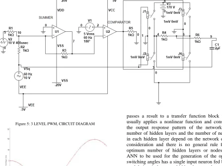
2.2 3-Level PWM
In order to create a signal which is closer to a true sine wave, a 3 level PWM signal can be generated with high, low, and zero voltage levels. For the resulting 3-level PWM signal to correspond to a sine wave, the signal comparison stage must also be 3-level. A triangle wave is used as it is in the 2-level PWM comparison, but it half the amplitude and summed with a square wave to compare one half of the sine reference signal at a time. The resulting PWM signal is used to control one half of an H-
Figure 4: 3 Level PWM comparison Control Signals
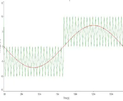
bridge which controls how long the bus voltage is allowed through to the load. The other half of the H-bridge controls the polarity of the voltage across the load, and is controlled by a simple square wave of the same frequency and in phase with the sine signal. Generally, this square wave can simply be created in a stage of the sine wave generation circuit. A virtual example of such a 3-level circuit we simulated is shown in figure 12. The resulting 3-level high-voltage PWM signal (figure 13) can be filtered into a very close approximation of the desired sine wave (figure 14). It should be noted that the simulations we did for this technique utilized a very low switching frequency for the triangle wave, so the PWM switching frequency is also low. This was done so
Figure 5: 3 LEVEL PWM, CIRCUIT DIAGRAM
Figure 6: Filtered Wave
that the waveforms would be easy to view and understand. In reality, a switching frequency above
20 kHz would be used to keep inductance ringing outside the range of human hearing.
3. Artificial neural networks
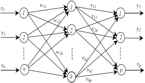
A typical multilayer ANN is shown in Fig.It consists of one input layer, a middle layer and an output layer, where each layer has a specific function. The input accepts an input data and distributes it to all neurons in the middle layer. The input layer is usually passive and does not alter the input data. The neurons in the middle layer act as feature detectors. They encode in their weights a representation of the features present in the input patterns. The output layer accepts a stimulus pattern from the middle layer
and
passes a result to a transfer function block which usually applies a nonlinear function and constructs the output response pattern of the network. The number of hidden layers and the number of neurons in each hidden layer depend on the network design consideration and there is no general rule for an optimum number of hidden layers or nodes. The ANN to be used for the generation of the optimal switching angles has a single input neuron fed by the modulation index, one hidden layer and s outputs where each output represents a switching angle.
The model of an artificial neuron can be represented by the op-amp summer-like configuration Shown in Fig. 8. It can be described by the following equation:
where,
y : the output of the neuron, xRiR: the ith input to the neuron,
wRiR : the ith connection weight,
wR0R: the bias weight,
σ (.): the transfer function of the neuron,
k : the number of connections with the neurons in the preceding layer.
4. Direct supervised training of ANN for SHE Back Propagation training Algorithm (BPA) is most commonly used in feed forward ANNs. When a set of input values are presented to the
ANN, step by step calculations are made in the forward direction to drive the output pattern. A cost functional given by the squared difference between the net output and the desired net output for the set of input patterns is generated and this is minimized by gradient descent method altering the weights one at a time starting from the output layer.
5. Comparison
References
[1] Power electronics, k.hari babu, scitech publiction (india) pvt.ltd.
[2] Power electronics, dr.p.s.bimbha, khanna publishers.fourth edition.
1T
[3] Fundamentals of power electronics,1T34Trobert warren
erickson1T34T,0T1T0T34Tdragan maksimović34T.
[4] Bishop,C.(1995).Neutral network for pattern recognition,clarendon press,oxford.
1T
[5] Power Electronics , Gupta & Singhal,Katson Books, 4P th
P
Edition, 2010
Figure 7: A Typical Multilayer ANN
Figure 8: Structure of a Single Neuron
Figure 9: Direct Supervised Training of ANN for SHE
[6] Aleksander, I., and J. Taylor (eds.) (1992), Artificial Neural Networks 2, Elsevier Science Publishers,
[7] Amari, S. (1977), “Neural Theory of Association and Concept Formation”, Biological Cybernetics, Vol. 26, pp. 175–185.
[8] Ramacher, U., and U. R¨uckert (1991), VLSI Design of Neural Networks, Kluwer, Boston, MA.
[9] Issa Batarseh, "Power Electronic Circuits" by John Wiley, 2003.
[10] S.K. Mazumder, "High-Frequency Inverters: From Photovoltaic, Wind, and Fuel-Cell based Renewable- and Alternative-Energy DER/DG Systems to Battery based Energy-Storage Applications", Book Chapter in Power Electronics handbook, Editor M.H. Rashid, Academic Press, Burlington, Massachusetts, 2010.
[11] V. Gureich "Electronic Devices on Discrete Components for Industrial and Power Engineering", CRC Press, New York, 2008, 418 p.
Sisir Mazumder B.Tech.(Electrical Engineering),ex-Dy.Manager (EE) with GAIL, and MBA(HRM)[IGNOU] is presently an Asstt.Professor with Gurunanak Institute of Technology, Kolkata-114, teaching various Electrical Engineering subjects as well as subjects such as Values and Ethics in Profession, Principles of Management etc. He also had taught at Techno India, Saltlake , Kolkata-91 for eight and a half years. The author had also worked with GAIL (A Govt. Of India Undertaking) for about six years (from 1989-95).He is currently a PhD research scholar with the Univ. Of Calcutta.
Susovan Dutta obatained his B.Tech degree in Electrical
Engineering from Techno India, Saltake in the year 2007 and M.E in Power Engineering from Jadavpur University in the year 2009.He is currently working as an Assistant Professor in the department of Electrical Engineering, Gurunanak Institute of Technology, Kolkata. His current research interest in Power System, application of Power Electronics Devices in Renewable Energy Systems, Distributed Generation.
Akash Samanta B.Tech.(Electrical) & MBA(Energy Management), working with an industrial organization since last one year.