Ciphers on AVR 8-bit Microcontrollers
Zhenzhen Bao, Peng Luo and Dongdai Lin
State Key Laboratory of Information Security, Institute of Information Engineering, Chinese Academy of Sciences, Beijing, China
{baozhenzhen, luopeng, ddlin}@iie.ac.cn
Abstract. Due to the demand for low-cost cryptosystems from industry, there spring up a lot of lightweight block ciphers which are excellent for some different implementation features. An innovative design is the block cipher PRINCE. To meet the requirement for low-latency and instantaneously encryption, NXP Semi-conductors and its academic partners cooperate and design the low-latency block cipher PRINCE. Another good example is the block cipher LED which is very compact in hardware, and whose designers also aim to maintain a reasonable software performance. In this paper, we demonstrate how to achieve high software performance of these two ciphers on the AVR 8-bit microcontrollers using bitslice technique. Our bitsliced implementations speed up the execution of these two ciphers several times with less memory usage than pre-vious work. In addition to these two nibble-oriented ciphers, we also evaluate the software performance of a newly proposed lightweight block cipher RECTANGLE, whose design takes bitslicing into consider. Our results show that RECTANGLE has very high performance ranks among the existing block ciphers on 8-bit microcontrollers in the real-world usage scenarios.
Keywords: PRINCE, LED, RECTANGLE, bitslice, block cipher, lightweight, cryptography, microcontroller, wireless sensor, AVR, ATtiny, implementation
1
Introduction
In several emerging areas and in the Internet of Things (IoT) era, where hundreds billion of highly constrained devices are interconnected, working together and typically communicating wirelessly, security and privacy can be very important. Cryptographic techniques will be required for those devices and will be implemented on more devices at present and in the future. For different application scenarios, there are different efficiency measures to evaluate whether a cryptographic technique can be applied to the scenarios. For hardware implementation, domi-nant metric are gate count (power, cost), energy, latency etc.. The corresponding application examples are RFID and low-cost sensors, healthcare devices and battery-powered devices, memory encryption, in-vehicle devices and industrial control systems. For software implementation, memory (ROM/RAM) and execution time are important measures. Again, application examples are in-vehicle devices, sensors and consumer electronics.
Compare with general purpose cryptographic algorithms, lightweight cryptographic primitives which relax implementation requirements have more advantages in those scenarios. In this paper, we mainly talk about block ciphers which are the most versatile of the symmetric ciphers. Lightweight block ciphers can overcome limita-tions of gate count in small chips, for examples a state of the art AES-128 [1] hardware implementation uses 2400 GE (Gate Equivalent) [7], while PRESENT-128 [5], LED-128 [3,4] and SIMON-128 [6] can respectively offer a 1391 GE [8], a 1265 GE [4] and a 1234 GE [6] implementation. As the gate count is small, energy con-sumption is small. In applications where instantaneous response is highly desired, lightweight primitives such as PRINCE [2] and SIMON can achieve same or less latency of AES with respectively 1/40 and 1/52 gate counts at 130nm low-leakage Faraday libraries. In other applications, such as sensor nodes or RFID tags, the equipped inexpensive microprocessor and microcontroller typically have a limited power budget and severely constrained memory (RAM and flash). For example, the ATtiny45 [11] has just 4 KBytes of flash, 256 bytes of RAM. There are lightweight ciphers, such as PRIDE [9] that can use no RAM and achieve similar throughput of AES with 1/2 flash bytes.
survey papers and open projects provide benchmarking results and reports on the performance of lightweight block ciphers [20,21,22,23,24,25,26,27,28,29,30,31,32,33].
On [25], a web page of ECRYPT II project, compact implementation and performance evaluation of 12 low-cost block ciphers on AVR ATtiny45 8-bit microcontroller are presented. The set of analyzed ciphers includes the low-cost ciphers designed until the corresponding paper [24] publication and thus it does not contain recent designs. The authors introduce a comparison metric that takes into account both the code size (ROM and RAM), the cycle count and the energy consumption. Implementation of the 12 ciphers comes from 12 different designers and codes are written in assembly. Both encryption, decryption and key management routines have to be imple-mented, and there is no usage scenarios (message length and mode of operation) involved. The authors of [29] implemented 21 low-cost (5 classical and 16 lightweight) block ciphers on the WSN430 sensor which is based on 16-bit TI MSP430 microcontroller. This is the biggest collection of low-cost ciphers implementations available on 16-bit microcontroller. However, as [32] points out, some of the implemented ciphers do not verify the test vectors. Both of the two above projects are not active for a long time.
Recently, a new benchmarking framework [32] was presented at the NIST Lightweight Cryptography Work-shop 2015 [36]. Learn from the strengths and weakness of those previous benchmarking frameworks, the authors manage to design a more flexible and powerful framework for evaluation of lightweight ciphers on different em-bedded devices commonly used in the IoT context. By the publication, they have studied software performance of 13 lightweight block ciphers on three different devices, 8-bit AVR, 16-bit MSP and 32-bit ARM. Their evalua-tion consideraevalua-tion involves two most typical usage scenarios that resemble security-related operaevalua-tions commonly performed by real-world IoT devices. They also maintain a web page [34] with the most recent results. Triathlon challenge [33] are announced to improve those results and collect more implementations and more performance evaluations of more newer designs. They introduce a “Figure of Merit” (FOM) according to which an overall rank-ing of ciphers can be assembled. The FOM metric can assign different weights to execution time, RAM footprint, and code size, and may even consider security aspects. In their evaluation, the FOM is a weighted sum of each cipher’s performance across three metrics: code size, RAM consumption and execution time.
Based on their current results in [32], the NSA designs Simon and Speck, AES and LS-designs are among the smallest and fastest ciphers on all platforms. Unfortunately, PRINCE which is superior as for low-latency and LED which is very compact as for hardware implementation get the lowest rank. Some newly proposed designs are also not included in their list, such as RECTANGLE [18] which is published in 2014 and presented at the NIST Lightweight Cryptography Workshop 2015 [36].
In this paper, we aim to contribute to the performance benchmarks of PRINCE, LED and RECTANGLE on 8-bit microcontrollers. Generally speaking, we expect to improve the performance of those ciphers on 8-, 16- and 32-bit microcontrollers. While, it seems reasonable to begin with 8-bit microcontroller, since the performance of those ciphers on 16- and 32-bit microcontrollers will be much better than that they can achieve on the bit, and 8-and 16-bit microcontrollers constituted an overwhelming part of the total microcontroller market [35]. Moreover, optimizations on the 8-bit microcontrollers can have strong reference meanings for that on the 16- and the 32-bit.
1.1 Related Work
For nibble-oriented and byte-oriented ciphers, people usually use look up tables (LUTs), which may need large memory to achieve high throughput. Both of PRINCE and LED can be seen as nibble-oriented. Specifically, the original components of the ciphers can be described as operations on nibbles (intra-nibbles and inter-nibbles). For PRINCE, there are two related efforts which aim to improve the software performance on 8-bit AVR microcon-trollers. In the first work [37], two implementations of PRINCE are presented. The first is T-table implementation which combines different operations within a round into a single table lookup operation. The second is block-parallel implementation which stores two nibbles in one register and processes them in block-parallel wherever possible. The S-boxes are stored as two 256-byte tables. In these two implementations, LUTs are too large to store in RAM. Thus they are coded in the programmable flash memory to which each access takes 1 more clock than that takes to the RAM.
simulations. Code in both of the two work was implemented in assembly. Performance evaluation in the first work involved cycles and code for nibble reordering, while it is unclear whether cycles and code for the nibble slicing are taken into account in the second work. Usage scenarios are not considered in both of the two work.
Work to improve the performance of LED on 8-bit AVR microcontrollers is quite rare. We can only refer to [34] for open source software implementation of LED on 8-bit microcontrollers. Unfortunately, the performance achieved by those C implementations in [32,34] are quite unsatisfactory.
1.2 Our Contributions
This work aims to improve the software performance of PRINCE and LED on 8-bit microcontrollers in two usage scenarios. By using bitslice technique instead of LUTs, we can minimize the requirement for memory and at the same time keep high throughput. In our implementations, by inventively rearrange the state bits, each message block can be processed in fine granularity parallel. By minimizing the number of instructions needed by each operation (S-boxes, MixColumns, ShiftRows etc.) of these ciphers, high throughput and low memory usage are achieved at the same time. Thus, these implementations can be used in serial message processing scenarios (corresponds to Scenario 1 2) in which the work [38] is hard to be used. It is quite natural to processing two blocks in parallel using our bitslice methods. Thus, in scenarios where message blocks can be processed simultaneously (corresponds to Scenario 2 2), our implementations also reduce the memory usage and execution time.
With respect to PRINCE, in Scenario 1, we achieve2.88×boost in throughput with1/1.23RAM and1/2.18 flash memory comparing with [32], achieve1.28×boost in throughput comparing with [37]. In Scenario 2, we achieve4.67×boost in throughput with the same RAM and1/2.09 flash comparing with [32], achieve similar throughput with1/9.17RAM and similar flash comparing with [38]. For LED, comparing with [32], our imple-mentation achieves6.12×boost in throughput with1/2.09 RAM and1/2.17flash in Scenario 1, and 11.27×
boost in throughput with the same RAM and1/2.72flash in Scenario 2. As shown in this work, PRINCE which gets a low rank in [32] is actually very efficient on 8-bit AVR devices.
We also aim to contribute performance benchmarks in the real-world usage scenarios of a newly proposed cipher RECTANGLE. Our results show that RECTANGLE gets very high ranks in those scenarios and can parallel SIMON in performance, see Table 3.
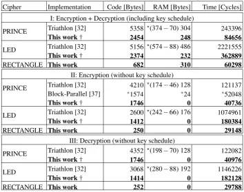
Table 1 and Table 2 summarize our results on the performance of PRINCE, LED and RECTANGLE in Sce-nario 1 and SceSce-nario 2, in which we also include the results of previous work to make comparisons.
The rest of the paper is organized as follows. Section 2 clarifies our target device, considering scenarios and performance measurement metrics. Section 3, 4 and 5 respectively demonstrate how to achieve high software performance of PRINCE, LED and RECTANGLE on the AVR 8-bit microcontrollers using bitslice technique. For each cipher, after a brief description, we exhibit how to rearrange the state bits, and how to implement its main operations in bitslicing with minimal number of instructions in two usage scenarios. Section 6 summarizes the results of this work.
2
Our AVR Implementations, Considering Scenarios and Performance Measurement
The specific target device in this work is the AVR ATmega128 8-bit microcontroller, which has 128 KBytes of flash, 4 KBytes of RAM and 32 8-bit general purpose registers. The ATmega128 uses an 8-bit RISC microproces-sor. The arithmetic and logical instructions are usually destructive source operand, i.e. destination register is one of the source registers. And most of the numeric processing instructions take one clock cycle. Instructions which load data from and store data to RAM take 2 clock cycles and that access to flash memory take 3 clock cycles. Opcode of most instructions uses 2 bytes, some special types uses 4 bytes. For a detailed introduction of 8-bit AVR instructions, please refer to [32] and [10]. To achieve optimal performance, we code the ciphers in assembly and the assembly code was written in and compiled using Atmel Studio 6.2. Cycle counts, code sizes and RAM usage are also determined using this tool.
For each cipher, we have implementations targeting to two scenarios which are introduced in [32].
Table 1: Results for Scenario 1 (encryption of 128 bytes of data using CBC mode)
Cipher Implementation Code [Bytes] RAM [Bytes] Time [Cycles]
I: Encryption + Decryption (including key schedule)
PRINCE Triathlon [32] 5358 ?(374−70) 304 243396
This work† 2454 248 84656
LED Triathlon [32] 5156 ?(574−88) 486 2221555
This work† 2374 232 362889
RECTANGLE This work 682 310 60298
II: Encryption (without key schedule)
PRINCE Triathlon [32] 4210 ?(174−46) 128 121137
Block-Parallel [37] ∗1574 ∗24 ∗52048
This work† 1746 0 40736
LED Triathlon [32] 2600 ?(242−66) 176 1074961
This work† 1412 0 180384
RECTANGLE This work 250 0 29148
III: Decryption (without key schedule)
PRINCE Triathlon [32] 4352 ?(198−70) 128 122082
This work† 1746 0 40976
LED Triathlon [32] 3068 ?(280−88) 192 1146226
This work† 1414 0 182128
RECTANGLE This work 252 0 29788
†State rearrangement operations on plaintext, ciphertext and round-keys are all included. ∗[37] evaluates the encryption of one block (3253 cycles), and the cost of dealing with the encryption mode is not included. We use 3253×16=52048 to estimate the cycles count. ?In this table and in Table 2 and 3, we subtract the stack consumption from the RAM usage of implementation in [32] and [34] to make a comparison considering the problem explained in Section 6.
Table 2: Results for Scenario 2 (encryption of 128 bits of data using CTR mode)
Cipher Implementation Code [Bytes] RAM [Bytes] Time [Cycles]
PRINCE Triathlon [32] 4420 (68−44)24 17271
Nibble-Slice [38] ∗2382 ∗220 ∗3606
This work(FixOrder) 2118 24 3696
This work(ReOrder) 2642 24 4236
LED Triathlon [32] 2602 (91−67)24 143317
This work(FixOrder) 956 24 12714
This work(ReOrder) 1480 24 13254
RECTANGLE This work(LessTime) 582 24 3405
This work(LowFlash) 428 24 3995
∗In [38] (processing two blocks in parallel in nibble-slicing), it is unclear whether cost of
Scenario 2 - Challenge-Handshake Authentication Protocol[32] This scenario covers the need of authentica-tion in the IoT. In the authenticaauthentica-tion protocol, the block cipher is used in CTR mode to encrypt 128 bits of data. The device has the cipher round keys stored in Flash memory and there is no master key stored in the device and consequently no key schedule is required. The data that has to be encrypted is stored in RAM, as well as the counter value. To reduce the RAM usage, the encryption process is done in place.
We consider the same three metrics of ciphers performance as considered in [32], including code size, RAM and execution time. Code sizes include the value of the Code and Data sections. Code section contains the bytes used by the binary code, Data section contains global initialized variables (such as the flash used by round con-stants etc.). The measurements do not consider the main function’s code size, where all the cipher operations are put together. RAM usage includes scenario specific RAM data, such as data to encrypt, master keys, round keys and initialization vectors. The execution time is expressed in number of processor cycles spent executing those procedures, such as encryption, key schedule or decryption. In addition, our measurement includes the cost taken by rearrangement operations on the plaintexts, ciphertexts and round keys.
3
PRINCE AVR Implementations
In this section, we present the first (to our knowledge) bitsliced implementation of the PRINCE cipher on 8-bit AVR microcontroller.
3.1 The PRINCE cipher
PRINCE operates on 64-bit blocks and uses a 128-bit keykwhich composed of two 64-bits elements,k0andk1. It is based on the so-called FX-construction. The 128-bit key is extended to 192 bits by the mapping:(k0||k1)→
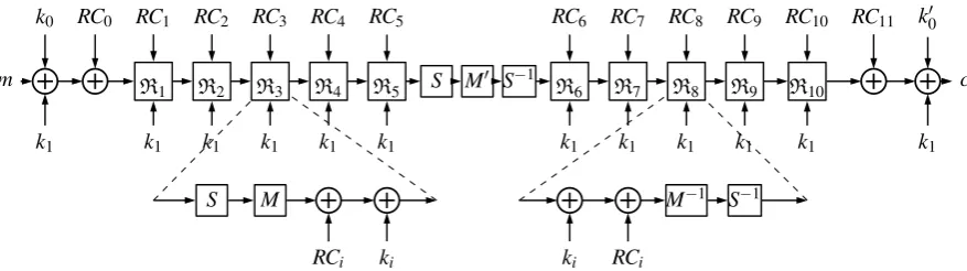
(k0||k00||k1) = (k0||(k0≫1)⊕(k063)||k1).k0andk00are used as whitening keys, whilek1is the 64-bit key used without updates by the 12-round block cipher refer to as PRINCEcore. The whole encryption process of PRINCE is depicted in Figure 1.
k0 RC0 RC1 RC2 RC3 RC4 RC5 RC6 RC7 RC8 RC9 RC10 RC11 k00
m R
1 R2 R3 R4 R5 S M
0 S−1
R6 R7 R8 R9 R10 c
k1 k1 k1 k1 k1 k1 k1 k1 k1 k1 k1 k1
S M M−1 S−1
RCi ki ki RCi
Fig. 1: The whole encryption process of PRINCE
PRINCE has anα-reflection property. Decryption can reuse the exact same procedure of encryption by simply
XOR a constantα to the third element k1of the extended key and exchange the used order betweenk0andk00. While, both procedures use the inverse round function as well as the round function.
The round function of PRINCE is AES-like, operates on a 4×4 state matrix of nibbles, which can be seen as composed of the following operations: KeyXor (correspond toki-add in the cipher specification) and RCXor (corresponds toRCi-add), S-box (corresponds to S-Layer), MixColumns (corresponds to The MatricesM0-layer) and ShiftRows (corresponds toSR, andSR◦M0=Mwhich is called the Linear Layer), among which only Mix-Columns is an involution. Thus, the implementations of the PRINCE have to instantiate the following operations: the KeyXor and RCXor, the S-box and inverse S-box, the MixColumns, the ShiftRows and Inverse ShiftRows. For more details about PRINCE please refer to [2].
3.2 PRINCE AVR Implementations
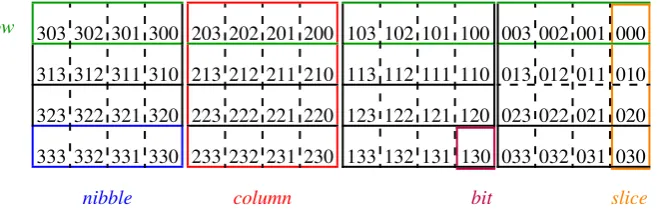
State Bits Rearrangement The original arrangement of the state can be seen in Figure 2. In this arrangement, successive four bits from right to left is called anibble, successive four nibbles from right to left is arow. Suc-cessive four bits from top to bottom is aslice, successive four nibbles from top to bottom is acolumn[40]. Bits are indexed in the form ofxyz, wherexis the column index (0 to 3 right-to-left),yis the row index (0 to 3 top-to-bottom) andzis the slice index (0 to 3 right-to-left) within a column. Then the right up corner can be seen as the origin of the state.
row 303 302 301 300
313 312 311 310
323 322 321 320
333 332 331 330
nibble
203 202 201 200
213 212 211 210
223 222 221 220
233 232 231 230
column
103 102 101 100
113 112 111 110
123 122 121 120
133 132 131 130
bit
003 002 001 000
013 012 011 010
023 022 021 020
033 032 031 030
slice
Fig. 2: The original arrangement of the state of bits for PRINCE
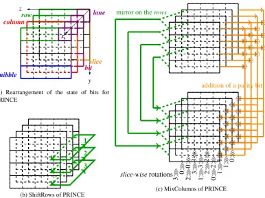
To bitsliced implement the operations, we gather the bits with index∗yz, i.e. bits with same row index and same slice index are gathered together. We call the resulted bit set alane1, in which all bits will be settled in the same register in our implementations. And we rearrange the state in a way as depicted in Figure 3a.
We then use the following conventions. Let Sdenotes the complete state, thenS[∗,y,z]denotes a particular lane. In implementations for Scenario 1, two lanes of one stateS[∗,y,z]andS[∗,y+2,z](y∈ {0,1},z∈ {0, . . . ,3}) are stored in one register, in the lower half and the high half respectively. In Scenario 2, two lanes of two states S[∗,y,z]andS0[∗,y,z](y∈ {0, . . . ,3},z∈ {0, . . . ,3}) are stored in one register to process two blocks in parallel.
The rearrangement of the state takes 2 clocks per bit using rotate through carry instructions (ROL and ROR). Thus, rearranging the input state and back rearranging the output state take 4 clocks per bits.
Bitsliced Implementation of the KeyXor and RCXor Since we have rearranged the encryption state, we should also rearrange the key and the round constant state in the same way. The KeyXor and RCXor operations can be merged together since they are continuous XOR operations. In Scenario 1, during the key schedule procedure, the master key is extended and the resulted 3 sub-keys are rearranged and XORed to the pre-rearranged round constants to generate round-key-constant materials. The resulted round-key-constant materials are then stored in RAM. In Scenario 2, the resulted round-key-constant materials is extended (to encrypt two blocks in parallel) and coded in flash memory.
Bitsliced Implementation of the S-box and the Inverse S-box By rearranging the state bits, we can implement the S-box and inverse S-box using logical operations instead of LUTs. In our rearrangement, 4 lanes within one row respectively correspond to the 4 input-outputs of S-boxes, thus 8 S-boxes can be computed in parallel using a logical instruction sequence operating on 8-bit registers, since 2 lanes share one register.
We firstly managed to find the bitsliced implementation of the 4×4 S-box (resp. inverse S-box) of PRINCE using an automatic search tool [41]. Operations in the resulted bitsliced implementations use the ‘operator des-tination, source1, source2’ instruction format. While in AVR ATtiny, instructions destination register is one of the source registers, i.e. it uses ‘operator destination, source’ instruction format. Thus, we translate the primary instruction sequences into two-operator instruction sequences manually. In our translation, we try to minimize the required clock cycles and realize in place process, i.e. the outputs are in the same registers as the inputs.
The primary bitsliced implementation of the S-box (resp. inverse S-box) of PRINCE need 17 (resp. 16) terms. Translating into AVR instructions, it turns to be an instruction sequence with length of 17+4=21 (resp. 16+ 6=22) with 4 (resp. 6) additional copy register (MOV) instructions. Taking advantage of the copy register pair (MOVW) instruction, and processing 16 S-boxes together instead of 8 S-boxes, the S-layer (inverse S-layer) of PRINCE needs 17×2+4=38 (resp. 16×2+6=38) instructions, instead of 21×2=42 (resp. 22×2=44).
lane
slice bit
row
column
nibble
x
y z
(a) Rearrangement of the state of bits for PRINCE
1
2
3
(b) ShiftRows of PRINCE
⊕⊕ ⊕⊕ ⊕⊕
⊕⊕ ⊕⊕
⊕⊕
⊕⊕ ⊕⊕
⊕⊕ ⊕⊕
⊕⊕ ⊕⊕
⊕⊕ ⊕⊕
addition of a parity bit
mirror on therows
3
≫ 0≫ 2≫ 3≫ 1≫ 2≫ 0≫ 1≫
0
≫ 3≫ 3≫ 2≫ 2≫ 1≫ 1≫ 0≫
slice-wiserotations
(c) MixColumns of PRINCE
Fig. 3: Rearrangement of the state of bits, ShiftRows and MixColumns of PRINCE
Bitsliced Implementation of the MixColumns According to observations on the linear layer of PRINCE in [39,40], MixColumns of PRINCE can be seen as being composed of three compositions: mirror on the rows, addition of a parity bit,slice-wise rotations by 0,1,2 or 3 positions. Thus, it can be expressed as the parallel application of 16 independent transformations operating on onesliceof the internal state. Figure 3c explains those transformations in a 3-dimensional way.
In our way of state bits rearrangement, 4 bits in the same position within 4 differentslicesare stored in the same register. Thus, parity bits of 8slicescan be computed in parallel. Mirror on therowsandslice-wiserotations can be combined to be a bits exchanging among differentlanes.
In our implementation for Scenario 1, since the lower half and the high half of one register hold lanes in two rows (laneS[∗,y,z]and laneS[∗,y+2,z]), addition of parity bit takes 7 instructions for 4 slices. Thus, addition of parity bit for the whole state takes 28 instructions per state. Since columnS[0,∗,∗]and column S[3,∗,∗]in stateSof PRINCE go through same MixColumns operations M0, sliceS[0,∗,z]and sliceS[3,∗,z]within column S[0,∗,∗]and columnS[3,∗,∗]go through same mirror and rotation operations forz∈ {0, . . . ,3}. Thus, bit 0 and bit 3 in a register, and bit 4 and bit 7 in a register go through same operations. Likewise, since columnS[1,∗,∗] and columnS[2,∗,∗]in stateSgo through same MixColumns operations M1, bit 1 and bit 2 in a register, and bit 5 and bit 6 in a register go through same operations. Finally, we achieve a 4-way parallel implementation for the combination between mirror on therowsandslice-wiserotations. That takes 2×9+2×8=34 instructions per state.
In our implementation for Scenario 2, since the lower half and the high half of one register hold some lanes in two states (laneS[∗,y,z]and laneS0[∗,y,z]), addition of the parity bit takes 8 instructions for 8 slices. Thus, addition of parity bit for the whole state takes 32 instructions for two states (thus 16 instructions per state). Similar to the implementation for Scenario 1, the 0, 3rd, 4th and 7th bit in a register go through same operations, and the 1st, 2nd, 5th and 6th bit in a register go through another set of operations. We also achieve 4-way and 8-way parallel implementations for the combination between mirror on therows andslice-wise rotations. That takes 4×16=64 instructions for 2 states (thus 32 instructions per state).
Bitsliced Implementation of the ShiftRows and the Inverse ShiftRows In our way of state bits rearrangement, ShiftRows and Inverse ShiftRows correspond to rotate bits inlanes, which are depicted in Figure 3b. Thus that needs to rotate the high half and the lower half of 8-bit registers separately in our implementation. We implement this by logical AND (AND), logical shift left and right (LSL and LSR), bit load from the T flag in SREG to a bit in register (BLD) and bit store from bit in register to T flag in SREG (BST) instructions.
With respect to Scenario 1, it takes 4×19=76 instructions to implement ShiftRows (or Inverse ShiftRows) per state. With respect to Scenario 2, it takes 4×19+2=78 instructions to implement ShiftRows (or Inverse ShiftRows) per 2 states (thus 39 instructions per state).
4
LED AVR Implementations
In this section, we present the first (to our knowledge) bitsliced implementation of the LED cipher on 8-bit AVR microcontroller.
4.1 The LED cipher
LED is a 64-bit block cipher, uses a key size from 64 to 128 bits, bases on an substitution-permutation network (SPN). The two primary instances, 64-bit key LED (named LED-64) and 128-bit key LED (named LED-128), respectively has 32 rounds and 48 rounds. In this paper, we will focus on LED-128. The key schedule of LED is very simple. In the case of LED-128, the master keykis composed of two 64-bit subparts,k=k1||k2, alternatively XORed to the internal state every 4 rounds. The 4-round operation between two key addition is called astep. The whole encryption process of LED is described using key addition andstepoperation, as depicted in Figure 4.
k1 k2 k1 k2 k1 k2 k1
P 4 rounds 4 rounds 4 rounds · · · 4 rounds 4 rounds C
| {z } one step
Fig. 4: The whole encryption process of LED
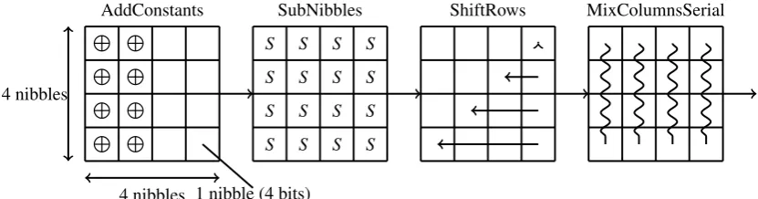
Similar to the round function of PRINCE, the round function of LED is also AES-like, which operates on a 4×4 state matrix of nibbles. It also uses the following operations AddConstants (round constant addition), SubNibbles (corresponds to SubCells in [4]), ShiftRows, and MixColumnsSerial. as illustrated in Figure 5. None of those operations is involution. Thus, we should also implement their inverse operations. For more details about LED, please refer to [4].
L L L L
L L L L
S S S S
S S S S
S S S S
S S S S
4 nibbles
4 nibbles 1 nibble (4 bits)
AddConstants SubNibbles ShiftRows MixColumnsSerial
4.2 LED AVR Implementations
State Bits Rearrangement We follow the same naming convention for PRINCE state mentioned above in Figure 3a to define the names of parts of LED state. Our rearrangement of LED state is quite similar to that of PRINCE state. A difference is that, in Scenario 1, each lane of LED state is stored in a whole 8-bit register, i.e. only the high half of the 8-bit register holds meaningful bits. Thus, 16 lanesS[∗,y,z]are respectively stored in 16 8-bit registers, leaving the lower half part of register empty. In Scenario 2, the lower half part of those 16 registers hold 16 lanes in another block state.
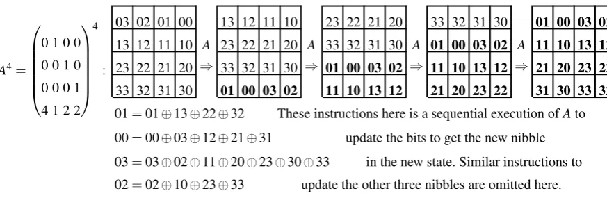
Bitsliced Implementation of the MixColumnsSerial In MixColumnsSerial, each column of the internal LED state is transformed by multiplying it once with MDS matrixM, whereM=A4.It can also be viewed as four serial applications of a hardware-friendly matrix A, which can be implemented using XOR and bit-permutation. Bit-permutation is free in hardware, but usually not free in software implementations. However, by observing the iterative processing procedure ofM=A4, which is depicted in Figure 6, we find that after 4 times of matrix mul-tiplication, the four bits in each nibble switched from the order (3,2,1,0) to the order (1,0,3,2). Since each register in our implementation stores bits at same position within different nibbles, this switching operation corresponds to an exchanging operation between registers. Since bits needed to be exchanged are located in same nibble, this switching operation can be combined with the S-box operation, thus there is no need to exchange registers in real. Thus, we can implement the MixColumnsSerial using sequential XOR instructions, and implement a bit-permutation variant of the original S-box. In addition, because of the four columns of the LED state go through same MixColumnsSerial operation, and due to our rearrangement of the state of bits, MixColumnsSerial opera-tions on four columns are done in parallel. In Scenario 1, we achieve a 4-way parallel implementation which needs 64 instructions per state, and in Scenario 2, we achieve an 8-way parallel implementation using 64 instructions for two states.
A4=
0 1 0 0
0 0 1 0
0 0 0 1
4 1 2 2
4
:
03 02 01 00 13 12 11 10 23 22 21 20 33 32 31 30 01 00 03 02
13 12 11 10 A 23 22 21 20 A 33 32 31 30 A 01 00 03 02 A 11 10 13 12
23 22 21 20 ⇒ 33 32 31 30 ⇒ 01 00 03 02 ⇒ 11 10 13 12 ⇒ 21 20 23 22
33 32 31 30 01 00 03 02 11 10 13 12 21 20 23 22 31 30 33 32
01=01⊕13⊕22⊕32 These instructions here is a sequential execution ofAto
00=00⊕03⊕12⊕21⊕31 update the bits to get the new nibble
03=03⊕02⊕11⊕20⊕23⊕30⊕33 in the new state. Similar instructions to
02=02⊕10⊕23⊕33 update the other three nibbles are omitted here.
Fig. 6: MixColumnsSerial of LED operate on one column
Bitsliced Implementation of the S-box and the Inverse S-box LED uses the PRESENT Sbox. There are pre-vious work in which bitsliced implementation of PRESENT Sbox is studied. In [38], the authors aim to improve the throughput of PRESENT using bitslice technique. Their 19-instruction AVR implementation of the PRESENT S-box based on the 14 terms representation found by Courtois in [43]. Using the automatic search tool [41], we try to find optimal bitsliced implementations of both PRESENT S-box and the inverse S-box. The best solutions also need 14 terms for PRESENT S-box and it needs 15 terms for the inverse S-box.
Similar to our work on PRINCE S-box, we also try to find the best translation from those general solutions to instruction sequences in AVR instruction set. Through our manual optimization, there are 4 additional instructions (mov) penalty to implement the S-box on AVR based on the 14 terms (resp. 15 terms) sequences. When take advantage of the MOVW instruction, and deal with two sets of 8-bit registers together, 32 instructions (resp. 34 instructions) are needed to finish 16 S-boxes (in Scenario 1, since the lower part of a register is left empty, it takes 64 instructions to execute 16 S-boxes).
and the inverse S-box, and the final instruction number is 33 for the 16 input-switched S-boxes and 34 for the 16 output-switched inverse S-boxes.
Bitsliced Implementation of the ShiftRows and the Inverse ShiftRows ShiftRows and the Inverse ShiftRows of LED are same with that of PRINCE. The difference between the implementations of the two ciphers is caused by the difference in the arrangement of the state bits in Scenario 1. 4×12=48 instructions are needed in Scenario 1 to rotate 16 lanes in one state and 4×19=76 instructions are needed in Scenario 2 to rotate 32 lanes in two states (thus 38 instructions to rotate 16 lanes in average).
5
RECTANGLE AVR Implementations
Presented at [36], RECTANGLE [18] is the most recent cipher discussed here, which is not involved in the ana-lyzed cipher list in [32]. Thus, in this paper, we aim to provide a software performance benchmark for this cipher to [34].
5.1 The RECTANGLE cipher
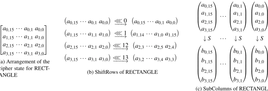
RECTANGLE operates on 64-bit cipher state. The key length can be 80 or 128 bits. In this paper, we mainly focus on the 128-bit key version (named RECTANGLE-128). The encryption is also based on an SP network. The substitution layer consists of 16 4×4 S-boxes in parallel, which is called SubColumn. The permutation layer is composed of 3 rotations, which is called ShiftRows. Figure 7 shows the arrangement of the cipher state, the SubColumn and ShiftRows operations. For more details about RECTANGLE, please refer to [18].
a0,15· · ·a0,1a0,0 a1,15· · ·a1,1a1,0 a2,15· · ·a2,1a2,0 a3,15· · ·a3,1a3,0
(a) Arrangement of the cipher state for RECT-ANGLE
a0,15· · ·a0,1a0,0
≪0
−−→ a0,15· · ·a0,1a0,0
a1,15· · ·a1,1a1,0
≪1
−−→ a1,14· · ·a1,0a1,15
a2,15· · ·a2,1a2,0
≪12
−−−→ a2,3· · ·a2,5a2,4
a3,15· · ·a3,1a3,0
≪13
−−−→ a3,2· · ·a3,4a3,3
(b) ShiftRows of RECTANGLE
a0,15 a1,15 a2,15 a3,15
· · ·
a0,1 a1,1 a2,1 a3,1
a0,0 a1,0 a2,0 a3,0
↓S · · · ↓S ↓S
b0,15 b1,15 b2,15 b3,15
· · ·
b0,1 b1,1 b2,1 b3,1
b0,0 b1,0 b2,0 b3,0
(c) SubColumns of RECTANGLE Fig. 7: Arrangement of the state of bits, SubColumns and ShiftRows of RECTANGLE
5.2 RECTANGLE AVR Implementations
State Bits Arrangement Since the main idea of the design of RECTANGLE is to allow fast implementations using bitslicing techniques, the state arrangement in the bitsliced implementation is quite straightforward. Each 16-bit row of the cipher state is held by 2 registers, thus 8 registers are needed to hold the cipher state.
Bitsliced Implementation of the ShiftRows The 1-bit rotation of the 16-bit row can be carried out using AVR’s logical shift left (LSL), rotate left through carry (ROL) and add with carry (ADC) instructions, together with an all 0 register. We mainly focus on implementing the 12-bit and 13-bit rotation of the 16-bit row with a minimized number of instructions. Thanks for our optimization on the 4-bit rotation (both left and right) of 16-bit row using swap nibbles (SWAP), copy register pair (MOVW), logical AND with immediate (ANDI) and exclusive OR (EOR) instructions and 2 temporary registers, it only needs 7 instructions to perform 12-bit rotation (both left and right) of the 16-bit row. Thus the total ShiftRows and the inverse ShiftRows only need 20 instructions per state.
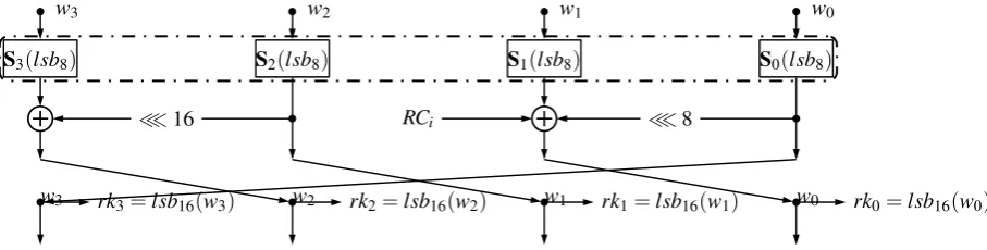
Bitsliced Implementation of the Key Schedule and Adding Round Key The 128-bit key state are arranged as a 4×32 matrix. The key schedule for RECTANGLE-128 consists of applying the 4×4 S-boxes to the 8 rightmost columns of the four 32-bit rows of the key state, 1-round generalized Feistel transformation on the 4 rows and 5-bit round constant XORing on a single row. The 64-bit round keyrkconsists of the 16 rightmost columns of the four 32-bit rows. Figure 8 shows the one round updating of the key state.
In our implementation, applying the 4×4 S-boxes to the 8 columns takes 14 logical instructions (28 bytes and 14 cycles), the 1-round generalized Feistel transformation takes 18 instructions (36 bytes and 18 cycles), the 5-bit round constant XORing takes 2 instructions (4 bytes and 4 cycles). There are two key bytes shared between every two successive round keys. According to this observation, we can use 8+25×6 bytes instead of 26×8 bytes to store 26 round keys. Meanwhile, by reordering the key bytes and using two additional registers, we can use 6 load instructions instead of 8 when adding the 8-byte round keys during encryption and decryption.
w3 w2 w1 w0
S3(lsb8) S2(lsb8) S1(lsb8) S0(lsb8)
≪16 RCi ≪8
w3 rk3=lsb16(w3) w2 rk2=lsb16(w2) w1 rk1=lsb16(w1) w0 rk0=lsb16(w0)
Fig. 8: One round key schedule of RECTANGLE-128, wherelsbnmeans taking thenleast significant bits
Our results are consistent with that shown in [18], while evaluation in this paper considers the two typical real-world usage scenarios. In addition, we develop a high throughput implementation (LessTime) and a low flash implementation (LowFlash) in Scenario 2. In the high throughput implementation, two blocks are processed simultaneously. Thus, it allows to load the subkeys one time every two blocks and reduce the cycles by sacrificing 146 bytes of flash than that in the low flash implementation which processes blocks one by one using a loop.
6
Results Summary and Comparisons
The vast majority of instructions used in our bitsliced implementations are types of instruction which takes one clock cycle and 2 bytes. And there is no memory access except for load inputs, load round keys, load round constants and store outputs. We write the whole program in assembly code. And executions of operations in our implementations are all in place in registers. Thus, there is no extra RAM used to store local variables during the whole executions of encryption, decryption and key schedule. While, that inevitably gives rise to difficulty when making a comparison with the inline assembly implementation in [32] or [34], in which stack RAM is needed and PUSH and POP instructions are used to store and restore all modified registers. Thus, in Table 1, 2 and 3, we subtract the stack consumption from the RAM usage of implementation in [32] or [34] to make a comparison. Besides, it would be hard to process blocks in parallel if comply with the C interface provided in [31].
For Scenario 1, our implementations include the key schedule and encryption, inverse key schedule (when needed) and decryption procedures. State rearrangement operations on the plaintext, ciphertext and round-keys are all included in our measurement. For Scenario 2, we only need to implement the encryption procedure, no decryption and no key schedule procedure are needed. Since encryption of 128-bit data using CTR mode, data is XORed with the output of the encryption procedure with counters as the input. There are two conventions on the usage of the two counters in our implementation for PRINCE and LED, because we rearrange the input of the encryptions. In the first convention, these two counters must be rearranged before going through the encryption procedure and must be back rearranged after the encryption procedure before XORed to the 128 bits message. We denoted this convention ReOrder. In the other convention, we encrypt the two counters directly and XOR the output with the 128-bit message without rearrangement of the state bits. We denoted this convention FixOrder. In our opinion, FixOrder convention does not relate to the security issues and is more efficient, thus it can be used as the final performance benchmark.
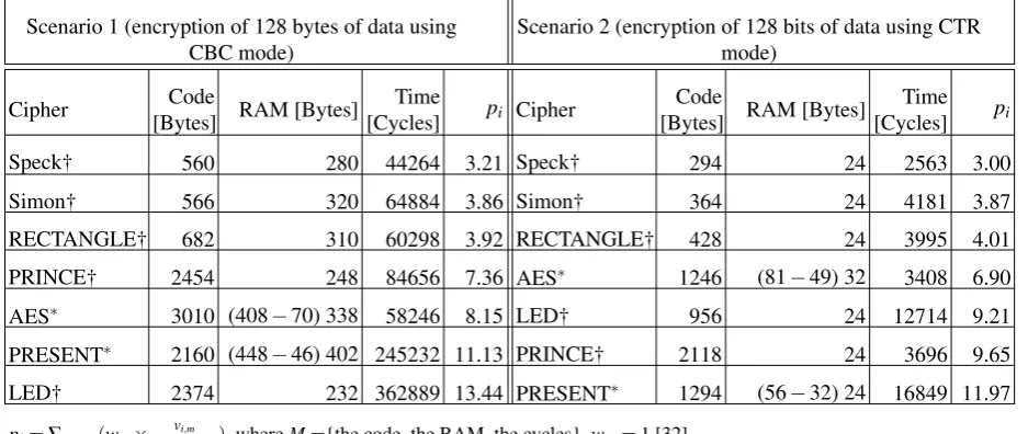
Our results on the performance of PRINCE, LED and RECTANGLE are summarized in Table 1 and Table 2, in which we also include the results of previous work to make comparisons. In addition, we have also implemented Simon and Speck in assembly according to the method provided in [45]. If use our results to update the results in [34], we get the following Table 3. Since AES and PRESENT are coded in assembly, we only include this two ciphers to make comparisons. As shown in Table 3, RECTANGLE get a higher rank than AES and slightly lower rank than SIMON both in Scenario 1 and Scenario 2. PRINCE and LED respectively get a higher rank than AES in Scenario 1 and higher rank than PRESENT in Scenario 2. We believe that comparison in [34] is inevitable unfair since only AES, PRESENT, SIMON and SPECK are coded in assembly. Several other ciphers may also get a performance improvement if coded in assembly. And as pointed above, there is also unfairness when making a comparison between an implementation using pure assembly code and an implementation using inline assembly code. Besides, it is difficult to compare the performance between ciphers which supports parallelization and which does not. We remain the optimization work on other ciphers and a more fair comparison to the future.
Table 3: Updated results for ciphers performance in Scenario 1 and Scenario 2
Scenario 1 (encryption of 128 bytes of data using CBC mode)
Scenario 2 (encryption of 128 bits of data using CTR mode)
Cipher Code
[Bytes] RAM [Bytes]
Time
[Cycles] pi Cipher
Code
[Bytes] RAM [Bytes]
Time [Cycles] pi
Speck† 560 280 44264 3.21 Speck† 294 24 2563 3.00
Simon† 566 320 64884 3.86 Simon† 364 24 4181 3.87
RECTANGLE† 682 310 60298 3.92 RECTANGLE† 428 24 3995 4.01
PRINCE† 2454 248 84656 7.36 AES∗ 1246 (81−49) 32 3408 6.90
AES∗ 3010 (408−70) 338 58246 8.15 LED† 956 24 12714 9.21
PRESENT∗ 2160 (448−46) 402 245232 11.13 PRINCE† 2118 24 3696 9.65
LED† 2374 232 362889 13.44 PRESENT∗ 1294 (56−32) 24 16849 11.97
pi=∑m∈M(wm× vi,m
mini(vi,m)), whereM={the code, the RAM, the cycles},wm=1 [32].
∗Results for assembly implementations in [34]. † Results for assembly implementations by this work.
Acknowledgement
Many thanks go to the anonymous reviewers. The research presented in this paper is supported by the National Natural Science Foundation of China (No.61379138), the “Strategic Priority Research Program" of the Chinese Academy of Sciences (No.XDA06010701).
References
2. Borghoff, J., Canteaut, A., Güneysu T., Kavun, E.B., Kneževi´c M., Knudsen, L.R., Leander, G, Nikov, V., Parr, C., Rech-berger, C., Rombouts, P., Thomsen, S.S., and Yalçn, T. PRINCE – A Low-Latency Block Cipher for Pervasive Computing Applications. In Wang, X. and Sako, K. (eds.) ASIACRYPT 2012, LNCS vol. 7658, pp.208–225, Springer, Heidelberg (2012).
3. Guo, J., Peyrin, T., Poschmann, A., Robshaw, M. The LED Block Cipher. In Preneel, B. and Takagi, T. (eds.) CHES 2011, LNCS vol. 6917, pp. 326–341, Springer, Heidelberg (2011).
4. Guo, J., Peyrin, T., Poschmann, A., Robshaw, M. The LED Block Cipher.http://eprint.iacr.org/2012/600. 5. Bogdanov, A., Knudsen, L.R., Leander, G., Paar, C., Poschmann, A., Robshaw, M.J.B., Seurin, Y., Vikkelsoe, C.:
PRESENT: An Ultra-Lightweight Block Cipher. In: Paillier, P., Verbauwhede, I. (eds.) CHES 2007. LNCS, vol 4727, pp.450–466. Springer, Heidelberg (2007)
6. Beaulieu, R., Shors, D., Smith, J., Treatman-Clark, S., Weeks, B., and Wingers, L. SIMON and SPECK: Block Ciphers for the Internet of Things.http://eprint.iacr.org/2015/585.
7. Moradi, A., Poschmann, A., Ling, S., Paar, C., Wang, H.: Pushing the Limits: a Very Compact and a Threshold Implemen-tation of AES. In: Advances in Cryptology EUROCRYPT 2011 30th Annual International Conference on the Theory and Applications of Cryptographic Techniques, vol. 6632, pp. 69 (2011)
8. Poschmann, A.: Lightweight Cryptography Cryptographic Engineering for a Pervasive World. PhD Dissertation, Faculty of Electrical Engineering and Information Technology, Ruhr-University Bochum, Germany (2009)
9. Albrecht, M.R., Driessen, B., Kavun, E., Leander, G., Paar, C., Yalçin, T.: Block Ciphers - Focus On The Linear Layer (feat. PRIDE). In: Garay, J., Gennaro, R. (eds.) CRYPTO 2014. LNCS, vol 8616, pp.57–76. Springer, Heidelberg (2014). 10. Atmel Corporation. 8-bit AVR Instruction Set,http://www.atmel.com/images/doc0856.pdf.
11. Atmel Corporation. AVR 8-bit Microcontrollers, http://www.atmel.com/products/microcontrollers/avr/ default.aspx.
12. Shirai, T., Shibutani, K., Akishita, T., Moriai, S., Iwata, T.: The 128-bit blockcipher CLEFIA (Extended Abstract). In: Biryukov, A. (ed.) FSE 2007. LNCS, vol 4593, pp.181–195. Springer, Heidelberg (2007).
13. Hong, D., Sung, J, Hong, S., Lim, J., Lee, S., Koo, B, Lee, C., Chang, D., Lee, J., Jeong, K., Kim, H., Kim, J., and Chee, S.. Hight: A new block cipher suitable for low-resource device. In Cryptographic Hardware and Embedded Systems – CHES 2006, volume 4249 of Lecture Notes in Computer Science, pp. 46–59. Springer, 2006.
14. De Cannière, C.,Dunkelman, O., Kneževi´c, M.:KATAN and KTANTAN - A Family of Small and Efficient Hardware-Oriented Block Ciphers. In: Clavier, C., Gaj, K. (eds.) CHES 2009. LNCS, vol 5747, pp. 272–288. Springer, Heidelberg (2009).
15. Gong, Z., Nikova, S., Law, Y.: KLEIN: A New Family of Lightweight Block Ciphers. In: Juels, A., Paar, C. (eds.) RFIDSec 2012. LNCS, vol 7055, pp. 1–18. Springer, Heidelberg (2012).
16. Wu, W., Zhang, L.: LBlock: A Lightweight Block Cipher. In: Lopez, J., Tsudik, G. (eds.) ACNS 2011. LNCS, vol 6715, pp. 327–344. Springer, Heidelberg (2011).
17. Suzaki, T., Minematsu, K., Morioka, S., Kobayashi, E.: TWINE : A Lightweight Block Cipher for Multiple Platforms. In: Knudsen, L., Wu, H. (eds.) SAC 2012. LNCS, vol 7707, pp. 339–354. Springer, Heidelberg (2012).
18. Zhang, W., Bao, Z., Lin, D., Rijmen, V., Yang, B., Verbauwhede, I.: RECTANGLE: A Bit-slice Ultra-Lightweight Block Cipher Suitable for Multiple Platforms. Science China Information Sciences, December 2015, Vol.58. Springer-Verlag Berlin Heidelberg (2015).
19. CryptoLUX: Lightweight Block Ciphers.http://www.cryptolux.org/index.php/Lightweight_Block_Ciphers. 20. Law, Y. W., Doumen, J., and Hartel, P. H.: Survey and Benchmark of Block Ciphers for Wireless Sensor Networks. ACM
Transactions on Sensor Networks (TOSN), 2(1):65–93, 2006.
21. Eisenbarth, T., Kumar, S., Paar, C., Poschmann, A., and Uhsadel, L.: A Survey of Lightweight-Cryptography Implemen-tations. IEEE Design & Test of Computers, 24(6):522–533, 2007.
22. Kerckhof, S., Durvaux, F., Hocquet, C., Bol, D., and Standaert, F.-X.: Towards Green Cryptography: A Comparison of Lightweight Ciphers From the Energy Viewpoint. In Cryptographic Hardware and Embedded Systems – CHES 2012, pp. 390–407. Springer, 2012.
23. Kneževi´c, M., Nikov, V., and Rombouts, P.: Low-Latency Encryption – Is Lightweight=Light+Wait? In Cryptographic Hardware and Embedded Systems – CHES 2012, pp. 426–446. Springer, 2012.
24. Eisenbarth, T., Gong, Z., Güneysu, T., Heyse, S., Indesteege, S., Kerckhof, S., Koeune, F., Nad, T., Plos, T., Regazzoni, F. et al.: Compact Implementation and Performance Evaluation of Block Ciphers in ATtiny Devices. In Progress in Cryptology – AFRICACRYPT 2012, LNCS 7374, pp. 172–187. Springer, 2012.
25. Eisenbarth, T., Gong, Z., Güneysu, T., Heyse, S., Indesteege, S., Kerckhof, S., Koeune, F., Nad, T., Plos, T., Regazzoni, F. et al.: Implementations of Low Cost Block Ciphers in Atmel AVR Devices.http://perso.uclouvain.be/fstandae/ lightweight_ciphers/, Feb. 2015.
26. Matsui, M. and Murakami, Y.: Minimalism of Software Implementation. In Fast Software Encryption, pp. 393–409. Springer, 2014.
27. Cazorla, M., Marquet, K., and Minier, M.: Survey and Benchmark of Lightweight Block Ciphers for Wireless Sensor Networks.http://eprint.iacr.org/2013/295.
28. Cazorla, M., Marquet, K., and Minier, M.: Survey and Benchmark of Lightweight Block Ciphers for Wireless Sensor Networks. In Pierangela Samarati, editor, SECRYPT 2013 – Proceedings of the 10th International Conference on Security and Cryptography, Reykjavík, Iceland, 29–31 July, 2013, pp. 543–548. SciTePress, 2013.
30. Dinu, D., Biryukov, A., Großschädl, J., Khovratovich, D., Corre, Y. L., Perrin, L.: FELICS – Fair Evalua-tion of Lightweight Cryptographic Systems. http://csrc.nist.gov/groups/ST/lwc-workshop2015/papers/ session7-dinu-paper.pdf, July 2015.
31. CryptoLUX.: FELICS (Fair Evaluation of Lightweight Cryptographic Systems),http://www.cryptolux.org/index. php/FELICS, 15 August 2015.
32. Dinu, D., Corre, Y. L., Khovratovich, D., Perrin, L., Großschädl, J., Biryukov, A.: Triathlon of Lightweight Block Ciphers for the Internet of Things,http://eprint.iacr.org/2015/209.
33. CryptoLUX.: FELICS Triathlon.http://www.cryptolux.org/index.php/FELICS_Triathlon, 12 August 2015. 34. Dinu, D., Corre, Y. L., Khovratovich, D., Perrin, L., Großschädl, J., Biryukov, A.: FELICS Block Ciphers Brief Results
and FELICS Block Ciphers Detailed Results. http://www.cryptolux.org/index.php/FELICS_Block_Ciphers_ Brief_Results,http://www.cryptolux.org/index.php/FELICS_Block_Ciphers_Detailed_Results, 1 Octo-ber 2015.
35. PROCESSOR WATCH.http://www.linleygroup.com, 8 Jan 2013.
36. National Institute of Standards and Technology (NIST). Lightweight Cryptography Workshop 2015.http://www.nist. gov/itl/csd/ct/lwc_workshop2015.cfm.
37. Shahverdi, A., Chen, C., and Eisenbarth, T.: AVRprince – An Efficient Implementation of PRINCE for 8-bit Microproces-sors. http://www.ashahverdi.com/files/papers/avrPRINCEv01.pdf. Technical Report, Worcester Polytechnic Institute, 2014.
38. Papapagiannopoulos, K.: High Throughput in Slices: The Case of PRESENT, PRINCE and KATAN64 Ciphers. In: Saxena, N. and Sadeghi, A. (eds.) Radio Frequency Identification: Security and Privacy Issues. LNCS, vol 8651, pp. 137–155. Springer International Publishing (2014).
39. Canteaut, A., Fuhr, T., Gilbert, H., Naya-Plasencia, M., and Reinhard, J.: Multiple Differential Cryptanalysis of Round-Reduced PRINCE. Presentation at Fast Software Encryption FSE 2014, London, UK. fse2014.isg.rhul.ac.uk/ slides/slides-09_4.pdf, 25 March 2014.
40. Canteaut, A., Fuhr, T., Gilbert, H., Naya-Plasencia, M., and Reinhard, J.: Multiple Differential Cryptanalysis of Round-Reduced PRINCE (Full version),eprint.iacr.org/2014/089.
41. Gladman, B.: Serpent S Boxes as Boolean Functions,http://www.gladman.me.uk/.
42. Bertoni, G., Daemen, J., Peeters, M., and Van Assche, G.: The Keccak Reference, January 2011,http://keccak. noekeon.org/.
43. Courtois, N. T., Hulme, D., and Mourouzis, T.: Solving Circuit Optimisation Problems in Cryptography and Cryptanalysis. Appears in electronic proceedings of 2nd IMA Conference Mathematics in Defence, UK, Swindon, 2011.
44. Boyar, J. and Peralta, R.: A New Combinational Logic Minimization Technique With Applications to Cryptology, in Experimental Algorithms, ser. Lecture Notes in Computer Science, P. Festa, Ed. Springer Berlin Heidelberg, 2010, vol. 6049, pp. 178–189.
45. Beaulieu, R., Shors, D., Smith, J., Treatman-Clark, S., Weeks, B., and Wingers, L.,: The Simon and Speck Block Ciphers on AVR 8-bit Microcontrollers.http://eprint.iacr.org/2014/947.