Available Online atwww.ijcsmc.com
International Journal of Computer Science and Mobile Computing
A Monthly Journal of Computer Science and Information Technology
ISSN 2320–088X
IMPACT FACTOR: 5.258
IJCSMC, Vol. 5, Issue. 5, May 2016, pg.464 – 477
Implementation of Detection and
Removal of Rain Streaks in an Image
Sneha Wandale
1, Prof.P.A.Tijare
2, Prof. S.N.Sawalkar
3¹Student, CSE Department, Sipna COET, Amravati, India ²Associate Professor, Sipna COET, Amravati, India
³Assistant Professor, Sipna COET, Amravati, India
Abstract— Weather can greatly degrade the performance of outdoor vision systems. Outdoor vision systems are used in various applications such as surveillance, navigation and tracking. To make outdoor vision systems robust to perform in all weather conditions, there is necessity to remove the effects of weather. The goal of our project is to remove rain streaks from the image while preserving the edges in the image. The method which we are implemented for the rain streak removal required MCA based image decomposition by performing dictionary learning and sparse coding. The proposed method has mainly three steps i.e. pre-processing, apply filter, image decomposition. After removal of rain streaks processing is easily done on the image. In the result, rain component has been successfully removed from the image. The proposed system is implemented in Matlab/ R2012a programming tool.This method removes rain streaks from single image.
Keywords— Image decomposition, online dictionary learning, sparse coding
I. INTRODUCTION
Image is the combination of several image components. Image decomposition is the approach of determining such image components and it can be used for the applications such as rain streaks removal, image de-noising. Because of the bad weather such as rain, fog, mist, haze will decreases the performance or quality of the scenes. The visual cause of rain is much complicated. The main components of rain is spatially distributed droplets which is falling at high velocities , in which each droplets will reflect and refract causes high variation in the intensity values of the scenes or images. Rain must be considered as a bright particle. If rain steaks is present in the atmosphere indicate that, it will not only degrade the quality of the scene but also it will degrade the performance of computer vision algorithm. For example, consider the case when the object trackers may fail if small portion of the image become occluded[1].
Outdoor vision applications mainly surveillance and navigation are used for various purposes. Some weather conditions, such as haze and rain, may influence computer vision functions. Rain removal in a single image is more difficult than in video since there is no temporal information for a single image[2].
© 2016, IJCSMC All Rights Reserved 465 camera parameters such as depth and exposure time of the scene can minimize the effects of rain without changing the scene appearance. The next approach is based on creating physics based framework for capturing rain streaks in the image or scene and thereby reduce effects of rain.
De-noising based approach is risky for removing noise from an images. The important purpose of de-noising approach is to create an algorithm that will eliminate noise from image in the case of additive noise. Latest approach in the field of image de-noising is based upon learning from sparse and redundant dictionary, in which each image component can be represented as basic signals for sparse decomposition.
The main objective of removing rain streaks and noise from images is to enhance the quality of the scene. Numerous approaches are introduced for enhancing the quality of the scene.
II. ANALYSIS OF PROBLEM
In existing system, in rain streaks removal that uses conventional MCA image decomposition. This conventional MCA image decomposition algorithms, are directly performed on an image in the pixel domain. But it is not easy to directly separate an image into its geometric (non-rain) and rain components in the pixel domain because in the rain image texture and rain component are highly mixed.
Because of this rain streaks dictionary learning process does not easily recognize the geometric (non-rain) atoms and rain atoms from the pixel-domain. This may lost too much image contents that belong to the geometric component but are invalidly classified to the rain component. So if anyone use this conventional MCA image decomposition for rain removal then they does not get the exact non-rain image[4].
Also, conventional MCA algorithms usually use a fixed global dictionary which depends on wavelets or curvelets to represent the geometric component of an image. Either a fixed global(global DCT) or a local (local DCT) dictionary is used for representing the textural component of an image. In the removal of rain streaks geometric component is the non-rain part in the image. Sometimes a learned dictionary may be also used to represent the textural component. To decompose an image into the geometric and textural components, the selection of dictionaries and related parameter is important.
III.PROPOSED WORK
Rain streaks in an image is one of the type of noise so for better appearance of an image it is necessary to remove this rain streaks component from the image. Elimination of noise is one of the important work to be done in computer vision and image processing, as noise leads to the error in the image. Existence of noise is manifested by undesirable information, which is not at all related to the image under study, but in turn interrupt the information present in the image[8].
Image decomposition will properly divide an image an image into texture and non-texture parts has been investigated in various applications of image compression, image inpainting, or related image analysis and synthesis tasks[5-7].
Following are the steps for removal of rain streaks in an image.
Step 1:Pre-processing
Initially select input image is in any size, if image is RGB image then convert it into grayscale image. Step 2: Apply Bilateral filter
After this it is required to resize that grayscale image in proper size because the algorithm need same size images in proper dimension. Here grayscale image is resize to 256x256 pixels.
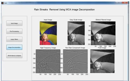
For the grayscale image in this step, we have to apply an edge preserving bilateral filter. After applying bilateral filter the grayscale rain image is decomposed into LF i.e. bilateral filtered image and HF part. LF part corresponds to the most basic information i.e. smooth regions. HF part corresponds to the rain streaks, edges or texture information. Bilateral filter is the non-linear, edge preserving, noise-reducing smoothing filter for the images. Further processing is done on the HF part[9].
Step 3: Image Decomposition
In this step image patches are extracted from HF part for learning dictionary of HF part (DHF). For obtaining
dictionary of HF component online dictionary learning algorithm is used. Dictionary is the collection of atoms. Dictionary can be viewed as matrix whose column are the atoms and atom can be considered as column vector[10-11].
The atoms in the DHF can be divided into two sub-dictionaries or clusters for representing the geometric
(non-rain) and rain components of high-frequency component.
Image gradient is used for extracting the most significant feature of rain atom. Image gradient is nothing but the directional change in the intensity or color in the image. The HOG feature descriptor is used to describe each atom in DHF. This feature descriptor is used for the object detection. The basic idea of HOG is that local object
directions across the pixels of the cell. The combined histogram enteries of all cell forms the HOG representation[3].
After extracting the each atom in DHF, then applying K-means algorithm for separating all of the atoms in DHF
into two sub-dictionaries D1 and D2.
For identifying which cluster consists of the rain atoms and which cluster consists of geometric atoms, for that we evaluate the variance of gradient direction for each atom dij, j=1,2,……N, in cluster Di, as VGij, also i=1, 2.
Then, evaluate the mean of VGij for each cluster Di as MVGi. Based on the fact that edge directions of rain
streaks in an atom are generally consistent, means, the rain atom has the small variance of gradient direction, then after this we identify the cluster with the smaller MVGi as rain sub-dictionary DHF_R and other one as
geometric (or non-rain) sub-dictionary DHF_G .
Then, perform sparse coding based on the two sub-dictionaries i.e. DHF_R and DHF_G for each patch extracted
from HF part to find its sparse coefficients by performing orthogonal matching pursuit algorithm. The objectives of sparse coding is to reconstruct an image patch as linear combination of a small number of vectors picked from dictionary[12-13]. Each reconstructed patch can be utilized to recover either geometric component or rain component of HF part based on the sparse coefficients, so that non-rain component of the high frequency part can be obtained from the HF part. By combining non-rain component of HF part with the LF part we get the rain removed version of the rain input image.
Fig.1 Steps for removal of rain streaks
IV.RESULT
© 2016, IJCSMC All Rights Reserved 467 Table 1: Parameter Description
Parameter Description
Required database Rain images
Resolution 256*256
Patch Size 16*16
Number of Iterations 100
Dictionary Size 1024
Following are GUI showing the result of removal of rain streaks by taking various input rain images
Screenshot 2:GUI showing performance analysis in terms of PSNR and VIF for Rain_image1
© 2016, IJCSMC All Rights Reserved 469 Screenshot 4:GUI showing performance analysis in terms of PSNR and VIF for Rain_image2
Screenshot 6: GUI showing performance analysis in terms of PSNR and VIF for Rain_image3
© 2016, IJCSMC All Rights Reserved 471 Screenshot 8:GUI showing performance analysis in terms of PSNR and VIF for Rain_image4
Screenshot 10:GUI showing performance analysis in terms of PSNR and VIF for Rain_image5
© 2016, IJCSMC All Rights Reserved 473 Screenshot 12:GUI showing performance analysis in terms of PSNR and VIF for Rain_image6
Screenshot 14:GUI showing performance analysis in terms of PSNR and VIF for Rain_image7
Image Quality Measures
Measurement of image quality is essential in various image processing applications. Image quality assessment is associated with the image similarity in which quality is depends on the differences between original image and the output image. Quality has been measured in following terms such as
1. Mean Squared Error (MSE) 2. Peak Signal to Noise Ratio (PSNR) 3. Visual Information Fidelity(VIF) 1. Mean Squared Error (MSE):
It is the mean squared difference between the original (input) image and output image. The mathematical definition for MSE is
In above equation, aij represent the pixel value at position (i, j) in the original image and bijrepresents the pixel
value at the same location in the corresponding output image. 2. Peak Signal to Noise Ratio (PSNR):
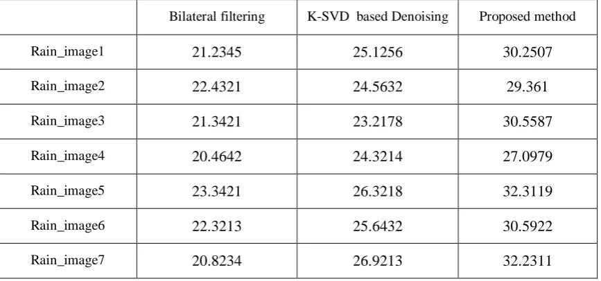
© 2016, IJCSMC All Rights Reserved 475 Table 2:Performance Comparison (in PSNR (dB)) using bilateral filtering, K-SVD based image denoising
method and our proposed method
Bilateral filtering K-SVD based Denoising Proposed method
Rain_image1 21.2345 25.1256 30.2507
Rain_image2 22.4321 24.5632 29.361
Rain_image3 21.3421 23.2178 30.5587
Rain_image4 20.4642 24.3214 27.0979
Rain_image5 23.3421 26.3218 32.3119
Rain_image6 22.3213 25.6432 30.5922
Rain_image7 20.8234 26.9213 32.2311
Table 2 shows performance comparison (in PSNR (dB)) using bilateral filtering,K-SVD based image denoising method and proposed method from which we can say that larger the PSNR value better is image quality.
3. Visual Information Fidelity(VIF):
VIF is the ratio of the two information measurements between input image and output image. It is given by
VIF=
where and other represents a set of N vectors from the jth sub-bands. VIF takes values between 0 and 1. VIF is exactly unity when the distorted image is identical to the reference image.VIF = 0 if all information was lost because of the distortion.
Table 3:Performance Comparison (in VIF) using bilateral filtering, K-SVD based image denoising method and our proposed method
Bilateral filtering K-SVD based Denoising Proposed method
Rain_image1 0.2345 0.3312 0.44387
Rain_image2 0.2254 0.3452 0.52086
Rain_image3 0.2134 0.3123 0.62088
Rain_image4 0.3321 0.3891 0.55101
Rain_image5 0.2621 0.4321 0.64497
Rain_image6 0.2146 0.4213 0.53449
Rain_image7 0.2012 0.2134 0.61816
Table 5.4 shows performance comparison (in VIF) using bilateral filtering, K-SVD based image denoising method and proposed method from this we say that larger the VIF value better is image quality.
Table4: Elapsed Time(in seconds)
Sr No
Image Elapsed Time (sec)
1 Rain_image1 116.08
2 Rain_image2 111.369
3 Rain_image3 102.102
4 Rain_image4 121.758
5 Rain_image5 142.366
6 Rain_image6 150.269
7 Rain_image7 143.442
From this proposed method we can say this method gives good result for removal of rain streaks from an image as compared with bilateral filter method and K-SVD image denoising method these method removes rain streaks from an image but they also remove image contents so that image quality not preserve by these method.
V. APPLICATIONS
There are various applications in which removal of rain streaks are used they are listed below
1) Image enhancement (Image enhancement is the process that improves visual quality in which resultant image is more suitable than original image. Also image enhancement improves the visual quality. Image enhancement is used for image smoothing. Smoothing is the process of noise removal. After removal of rain streaks i.e. noise we can easily detect features in the image.)
2) Preprocessing of several computer vision systems, such as object detection, tracking, classification or recognition, indexing, and retrieval.(Computer vision is a field that analyse and interpret the contents in the image i.e. acquiring, processing and understanding images. Rain streaks degraded performance of computer vision system. By removal of the rain streaks we can easily detect object. Also retrieval of particular object is done easily. Also classification of detected object into different categories is easy.)
VI.CONCLUSION
From this work it can be concluded that the proposed method performs well work for the rain streaks removal in an image. The main purpose of the single image-based rain streaks removal system is to develop an efficient method for removing rain streaks from images, that improves or enhances the visual quality of rain degraded images and also preserves the original image details. Rain removal technique can be formulated as an image decomposition problem that based on MCA. So that it is possible to remove, rain component from the image while retaining most geometrical details in image.
The proposed method uses single image for removal of rain streaks. This method is suitable for only rain streaks removal. The results means output non-rain image show that this method could reduce the degradation caused by dynamic weather and also maintain information of the image. By using image decomposition we are able to separate rain and non-rain part from the image.
R
EFERENCES[1] K. Garg and S. K. Nayar, “Vision and rain,” Int. J. Comput. Vis., vol.75, no. 1, pp. 3–27, Oct. 2007. [2] K. Garg and S. K. Nayar, “When does a camera see rain?,” in Proc. IEEE Int. Conf. Comput. Vis., Oct.
2005, vol. 2, pp. 1067–1074.
[3] N. Dalal and B. Triggs, “Histograms of oriented gradients for human detection,” in Proc. IEEE Conf. Comput. Vis. Pattern Recognit., San Diego, CA, Jun. 2005, vol. 1, pp. 886–893.
© 2016, IJCSMC All Rights Reserved 477 [6] J. Bobin, J. L. Starck, J. M. Fadili, Y. Moudden, and D. L. Donoho, “Morphological component analysis:
An adaptive thresholding strategy,” IEEE Trans. Image Process., vol. 16, no. 11, pp. 2675–2681,Nov. 2007.
[7] J. M. Fadili, J. L. Starck, J. Bobin, and Y. Moudden, “Image decomposition and separation using sparse representations: An overview,” Proc.IEEE, vol. 98, no. 6, pp. 983–994, Jun. 2010.
[8] A. Buades, B. Coll, and J. M. Morel, “A review of image denoising algorithms, with a new one,” Multisc. Model. Simul., vol. 4, no. 2, pp.490–530, 2005.
[9] C. Tomasi and R. Manduchi, “Bilateral filtering for gray and color images,” in Proc. IEEE Int. Conf. Comput. Vis., Bombay, India, Jan. 1998,pp. 839–846.
[10] J. Mairal, F. Bach, J. Ponce, and G. Sapiro, “Online learning for matrix factorization and sparse coding”,J.Mach.Learn.Res.,vol.11,2010.
[11] M. Elad and M. Aharon, “Image denoising via sparse and redundant representations over learned dictionaries,” IEEE Trans. Image Process., vol. 15, no. 12, pp. 3736–3745, Dec. 2006.
[12] J. Mairal, M. Elad, and G. Sapiro, “Sparse representation for color image restoration,” IEEE Trans. Image Process., vol. 17, no. 1, pp.53–69, Jan. 2008.