COMBAT ROBOT WITH GUN AND CAMERA
1
Deepak Kumar Singh,
2Ashutosh Gaur,
3Deepak, Arvind Kumar
4 1,2,3UG Student, Department of Electronics and Communication,
4Associate. Prof, Dept. of ECE, Accurate Institute Of Management and Technology, Greater Noida
ABSTRACT
This paper presents the behavior and applications of a combat robot with gun and camera. This robot is basically having a future scope to tackle the 26/11 Mumbai like situations. Here a purpose of this paper is also to understand the working and applications or moreover one can say importance of microcontroller. Here a spy camera has been installed on it, so that the location can be remotely accessed. This mobile controlled robot is designed for spying purpose in the enemy area or some unknown area with 12 different channels for control operation and a very high range, from anywhere in the world. A laser or any gun is installed with the robot. It can be used to avoid the loss of life as it is very precious. So it is a good replacement of a human in terrorists attack. Let us see the main features of this Robot. Mobile as a transmitter is used having 12 keypad for control operation and can be used from anywhere in the world. Programmable, multifunctional, DTMF based receiver. It has Day Night sensor which sense light condition in case of low light high brightness LED glow automatically. It can move left, right, Forward, Backward and has a obstacle sensor to detect unwanted things on the path.
Keywords: Combat Robot, DTMF Based Receiver, Automatic Control Machine.
I INTRODUCTION
The global focus on terrorism and security may have geared up following the 9/11 attacks in the USA. Robotics
develop man-made mechanical devices that can move by themselves, whose motion must be modeled, planned,
sensed, actuated and controlled, and whose motion behavior can be influenced by “programming”. Robots are called
“intelligent” if they succeed in moving in safe interaction with an unstructured environment, while autonomously
achieving their specified tasks. The risk of terrorist attack can perhaps never be eliminated, but sensible steps can be
taken to reduce the risk. The word “Robot” was first used in a 1921 play titled R.U.R. Rossum’s Universal Robots,
by Czecho slovakian writer Karel Capek. Robot is a Czech Word meaning “worker.”
This definition implies that a device can only be called a “robot” if it contains a movable mechanism, influenced
by sensing, planning, and actuation and control components. Robotics is, to a very large extent, all about system
integration, achieving a task by an actuated mechanical device, via an “intelligent” integration of components,
many of which it shares with other domains, such as systems and control, computer science, character animation,
machine design, computer vision, artificial intelligence, cognitive science, biomechanics, etc. In addition, the
domains (vision, biology, cognitive science or biomechanics, for example) are becoming crucial components in
more and more modern robotic systems.
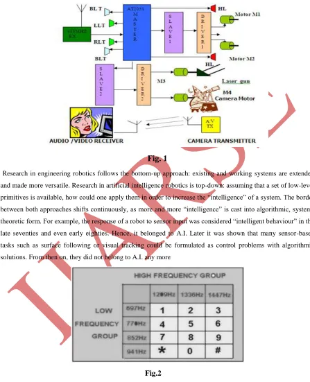
Fig. 1
Research in engineering robotics follows the bottom-up approach: existing and working systems are extended
and made more versatile. Research in artificial intelligence robotics is top-down: assuming that a set of low-level
primitives is available, how could one apply them in order to increase the “intelligence” of a system. The border
between both approaches shifts continuously, as more and more “intelligence” is cast into algorithmic,
system-theoretic form. For example, the response of a robot to sensor input was considered “intelligent behaviour” in the
late seventies and even early eighties. Hence, it belonged to A.I. Later it was shown that many sensor-based
tasks such as surface following or visual tracking could be formulated as control problems with algorithmic
solutions. From then on, they did not belong to A.I. any more
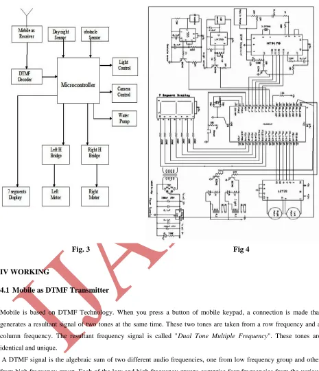
Fig.2
Fig. 3 Fig 4
IV WORKING
4.1
Mobile as DTMF Transmitter
Mobile is based on DTMF Technology. When you press a button of mobile keypad, a connection is made that
generates a resultant signal of two tones at the same time. These two tones are taken from a row frequency and a
column frequency. The resultant frequency signal is called "Dual Tone Multiple Frequency". These tones are identical and unique.
A DTMF signal is the algebraic sum of two different audio frequencies, one from low frequency group and other
from high frequency group. Each of the low and high frequency groups comprise four frequencies from the various
keys present on the telephone keypad; two different frequencies, one from the high frequency group and another
from the low frequency group are used to produce a DTMF signal to represent the pressed key. When you send
these DTMF signals to the telephone exchange through cables, the servers in the telephone exchange identifies these
Fig 2. When you press the digit 5 in the keypad it generates a resultant tone signal which is made up of frequencies
770Hz and 1336Hz. Pressing digit 8 will produce the tone taken from tones 852Hz and 1336Hz. In both the cases,
the column frequency 1336 Hz is the same. These signals are digital signals which are symmetrical with the
sinusoidal wave.
4.2
Receiver Part
The whole Receiver circuit consists of 6 major parts
DTMF Receiver Light Sensor Fire sensor
7 segment display DC Motor driver Microcontroller logic
4.3
DTMF Receiver
Mobile work as a DTMF receiver and encoded hybrid frequency DTMF code tone is decoded by 8870 IC. 8870
Decode DTMF tone and convert into BCD code, output depending upon which key is pressed at the transmitter side.
This four digit output is directly given to 89C51. It will collect this code and start comparing it with inbuilt code.
When it founds perfect match it display code on 7 segment display and switch to that subroutine and perform that
particular task. The table shows decoded output
Pressed Mobile key
D3
D2
D1
D0
1
0
0
0
1
2
0
0
1
0
3
0
0
1
1
4
0
1
0
0
5
0
1
0
1
6
0
1
1
0
7
0
1
1
1
8
1
0
0
0
9
1
0
0
1
*
1
0
1
0
0
1
0
1
1
#
1
1
0
0
Table -1
4.4
Light sensor
The LDR light sensor is used to sense intensity of light. In the light sensor we use IC 555 as a main component. Pin
no 4 and pin no 8 is connected to the positive supply. Pin no 1 is connected to the negative voltage. One capacitor is
no 2. In the case of infra red sensor Pin no 2 is negative bias through the 33k ohm resistor and pin no is positively
biased through the LDR.
In normal day condition when light is focusing on the LDR then pin no 2 is positively biased photodiode. If pin no 2
is positive than negative output is available on the pin no 3. Now in night there is no light on the photodiode and pin
no 2 is now gets its voltage from only 33 k ohm resistor. If pin no 2 is become negative then output is shifted to the
pin no 3. When positive output is available on the pin no 3 and with the help of this voltage NPN transistor is on and
npn transistor provide a negative voltage as a pulse to the microcontroller.
4.5
Segment Display
The DM74LS47 accepts four lines of BCD (8421) input data, generates their complements internally and decodes
the data with seven AND/OR gates having open-collector outputs to drive indicator segments directly. Each segment
output is guaranteed to sink 24mA in the ON (LOW) state and withstand 15V in the OFF (HIGH) state with a
maximum leakage current of 250 mA. Auxiliary inputs provided blanking, lamp test and cascadable
zero-suppression functions.
4.6
DC motor driver:
The H-Bridge is used for motor driver. The H-Bridge is widely used in Robotics for driving DC motor in both
clockwise and anticlockwise. As shown in the circuit diagram in H Bridge two NPN and two PNP transistors is
used. Let us consider microcontroller provide high at pin No 13 and low at Pin No 14 thus right side NPN transistor
conducts and left side PNP transistor conducts. This means M12 is 12v and M11 is grounded thus motor rotate
clockwise. Again let us consider microcontroller provide low at pin No 13 and high at Pin No 14 thus right side PNP
transistor conducts and left side NPN transistor conducts. this means M12 is grounded and M11 is 12v thus motor
rotate anticlockwise..
4.7
Microcontroller Logic
The function of microcontroller is to control input output based on the programmed embedded hex logic. The
microcontroller continuously scans input logic. The input logic is 4BCD data from 8870 one from fire sensor and
one from light sensor. If any one of them changes their logic level microcontroller goes to particular subroutine and
perform particular task.
Let us consider a case at the transmitter mobile I have pressed number 2, thus at receiver side 8870 generate
corresponding BCD logic 0010. The microcontroller receive 0010 at pin no 1,2,3,4. The microcontroller is
programmed if input is 0010, move to robot left. The robot will moves left if left DC motor rotate slow and right DC
motor rotate fast. This slow and fast moment is done by microcontroller using pulse width modulation. Thus when
we press 2 key microcontroller provide different pulse to left right motor. The right motor gets pulse having mote on
If microcontroller sense 0001 input then it goes to right subroutine and moves robot right.
If microcontroller sense 0010 inputs then it goes to left subroutine and moves robot left.
If microcontroller sense 0011 input then it goes to stop subroutine and goes to standby mode.
If microcontroller sense 0100 input then it goes to forward subroutine and moves robot forward.
If microcontroller sense 0101 input then it goes to backward subroutine and moves robot backward.
If microcontroller sense 0110 input then it goes to camera subroutine and supply high pulse to start camera and
video transmission.
If microcontroller sense low input at pin No 5 then it goes to day night subroutine and supply high pulse to on light.
If microcontroller sense low input at pin No 6 then it goes to fire subroutine and supply high pulse to on water pump
for controlling fire.
4.8
Transmitter for laser gun
The transmitter is constituted by AT90S2323 microcontroller and TLP434 RF transmitter module at 418MHz.
Transmitter is designed for more battery economy and safe transmission of the data. Here TLP434A is an
Ultra-small Trasmitter of range .418MHz with ASK modulation scheme with operating voltage range from 2-12 dc
voltage. This IC is usually chained with the encoder IC for example HT12-E. This transmitter is connected to the
AT90S2323 10MHz with 2k flash microcontroller. This constitutes a transmitter section of laser gun.
4.9
Receiver for laser gun
The receiver constituted by RF receiver module RLP434A at 418MHz, the microcontroller AT90S2313 [10] and the
two relays which can handle any electric (or electronic) device up to 10 Amps (the contacts of my relays are 10Amp
at 250Volts). The RLP434A is an RF receiver module with receipt frequency at 418MHz with ASK modulation.
There are 2 outputs from this module, the digital, with levels from 0v to VCC (5 volts in our case) and the analog
output. Analog output is not used. The transmitter sends 4 bytes with 2400bps 4 times and the receiver RLP-434A
collects them and moves them to AT90S2313 to RxD pin, PD0.
4.10
JMK AV Receiver with Wireless Camera
It is mini wireless monitoring video camera and wireless receiver set for home and small business surveillance and
is used here for demonstration purpose. Simply install the wireless camera in the room where we want to monitor
and set the wireless receiver in the next room (up to 15 meters away) and hook it up to a TV or DVR to watch the
action or record the footage for the security records. Here we are placing this wireless camera in the combat robot.
4.11
TV Capture card
A TV capture card is a computer component that allows television signals to be received by a computer. It is a kind
of television tuner. Most TV tuners also function as video capture cards, allowing them to record television
programs onto a hard disk. The card contains a tuner and an analog-to-digital converter along with demodulation
and interface logic.
Fig.6. ATI Digital TV Capture Card
4.12
Remote Controller Decoder SC2272-T4
It can be used for wireless remote control receivers and its features are
Operating voltage: DC 4~6V. Up to 12 tri-state code address pins.
Up to 6 data pins. Toggle control mode.
V SOFTWARE IMPLEMENTATION
For the software implementation, we deploy two software packages. First one is the Keil μVision 3.0. second one is the Flash magic simulator. The Keil μVision Debugger A/D Converter, D/A Converter, and PWM Modules) of
89S52device. Simulation helps to understand hardware configurations and avoids time wasted on setup problems.
With simulation, we can write and test applications before target hardware is available. The system program written
in embedded C[11]using KEIL IDE software will be stored in Microcontroller. Keil development tools for the
Microcontroller architecture support every level of software developer from the professional applications engineer to
the student for learning about embedded software development. The industry-standard Keil C Compilers, Macro
Assemblers, Debuggers, Real- time Kernels, Single-board Computers, and Emulators support all 89S52 derivatives.
The Keil Development Tools are designed to solve the complex problems facing embedded software developers.
Flash magic is used to dump the code to microcontroller from PC. Flash Magic is a free, powerful, feature-rich
Windows application that allows easy programming of Philips FLASH Microcontrollers. Build custom applications
for Philips Microcontrollers on the Flash Magic platform! Use it to create custom end-user firmware programming
is a tool that runs under Windows 95/98/NT4/2K. It allows in-circuit programming of FLASH memories via a serial
RS232 link. Computer side software called Flash Magic is executed that accepts the Intel HEX format file generated
from compiler Keil to be sent to target microcontroller. It detects the hardware connected to the serial port.
VI RESULTS AND DISCUSSION
Remote controllers are designed to direct the orientation of robot and to operate the laser gun mouned on a wheel,
which is controlled with a DC geared motor. Robot keeps on moving in two modes i.e., Manual mode and
self-mode. It’s brought under user’s control in the case of manual self-mode. In self-mode, robot starts moving over surface
and takes action according to the scenario. To detect the obstacles, we have deployed Infrared sensors (left sensor
and right sensor) in the front portion of the module. While moving on the surface, if the left sensor is detected, robot
takes back the position for a moment and moves right. If the right sensor is detected, robot gets back and moves left.
Top view and front view are shown in the fig 7 and 8 respectively.
Fig. 7 Fig. 8
VII APPLICATIONS
Can be adequately implemented in national defense through military-industrial partnership.
Can be vastly applied in Resorts, borders of noted buildings.
Installation of combat robots in the stadiums, sacred places, government and non government organizations
assures top security.
VIII CONCLUSION
As we all know, these days India is sick off massive terror attacks by middle east and other near countries, bomb
explosions at plush resorts. To avoid such disasters TECHNOLOGICAL power must exceed human power. No
doubt, Human life and time are priceless. It’s our onus to take an initiative to design a model of a robot for defense
and other purposes that meets combatant needs. So to avoid terror attacks and to ensure more security at the border
and high density areas it’s wise to maintain a world class military technology in accordance with combatant needs. It
is also helpful in robbery and theft like incidents. Even every nation needs its own defense system for their integrity
and security. In such a way construction of these robots will carry nation’s name, fame globally. So it is a pride to
design such a robot with a great future scope.
REFERENCES
[1] Pete Miles & Tom Carroll, Build Your Own Combat Robot, (2002).
[2] Asaro,P. How just could a robot war be?, Frontiers in Artificial Intelligence and Applications, 75, 50-64.
[3] S. Y. Harmon & D. W. Gage, “Current Technical Research Issues of Autonomous Robots Employed In