ABSTRACT
The Very High Temperature Reactor (VHTR) core is constituted of prismatic graphite blocks (fuel and reflectors), enclosed within a metallic core barrel. This design is common to several HTR reactor types such as AREVA ANTARES Project, GT-MHR [1] and HTTR [3]. The whole structure is constituted of nearly 2600 blocks and is cooled by pressurised helium gas. The necessity to withstand thermal dilatations and the probable occurrence of graphite shrinkage under irradiation implies the existence of significant gaps between adjacent block columns and clearances in the linking systems between piled up blocks. The seismic behavior of such assembly is largely non linear and includes frictional sliding, impacts and blocks rocking. Nevertheless, it requires a detailed understanding in order to:
• Respect the safety criteria against seismic aggression, which include keeping the graphite blocks integrity and limiting the transversal displacements of the control rod channels.
• Model and control the interactions between the core and the other internal components of the reactor vessel.
A research program is performed by CEA, EdF and AREVA, with experimental and theoretical parts. Tests have been performed on a few graphite blocks. The interpretation of the experiments provides the opportunity to test and to choose numerical methods to describe the dynamic behavior and allows the determination of the corresponding parameters. Numerical simulations of the seismic behavior of the whole core lead to first estimations of the kind of movements the blocks can undergo.
INTRODUCTION
Many works have been done in the field of the seismic response of graphite nuclear core assemblies, since the 70’s, for different kinds of gas-cooled reactors. The seismic behavior is largely non-linear and is related with the non-linear problem of the dynamic of rocking-sliding blocks.
The safety factors which have been considered are: the shear-bending strength of the dowel pins between the blocks, the functional operability in terms of maximal strain criterion and maximal displacements of the control rod channels, and the integrity of the lateral keying between the graphite blocks.
Several authors have developed analytical models, where blocks are treated as rigid solids, allowing horizontal motion and rocking (face to face contacts, shear taken into account through the dowel-pins system) with lateral friction. These models used rigid solids lined by contact spring damper elements, with Coulomb’s friction. They frequently made the assumption that displacements and rotations are small, in order to simplify the models. Figure 1 shows an example of experiments and of numerical results of the movements of the blocks [2].
A common work program for the VHTR project is defined and carried out by the three partners of the present paper: AREVA, CEA, and EdF in France. As for previous studies on the seismic behavior of HTR and Gas reactors (GT-MHR [1], HTTR [3], AGR [4], [5]…), the program is divided into an experimental and an analytical part:
Figure 1 : experimental ant theoretical studies [2]
The main phases of the program are:
• The choice of numerical methods to simulate the dynamic behavior of the blocks,
• The interpretation of experimental tests on a few blocks (scale 1) aimed at validating the choice of the model, and acquiring the values of the parameters of the model,
• The performing of simulations on a whole HTR core, using the previous model, in order to get some first understanding of the seismic behavior,
• The conduct of experimental tests on a large number of blocks in order to validate the model. 1 Theoretical model for the impacts between blocks
Before we apply FEM simulations to the HTR core seismic analysis, it is compulsory to gather knowledge on the ability of available numerical methods and algorithms to model with a sufficient accuracy the non-linear and non-smooth transient dynamic history of the mechanical system. In particular, we have to fix the choice of specific numerical characteristics as:
• implicit versus explicit time-integration schemes (Newmark, HHT, central differences…),
• numerical damping coming from time-integration schemes, with respect to the physical damping, coming from restitution coefficient,
• time-stepping definition, according to the successive transient dynamics steps (free rocking, collision), • frictional contact algorithm: penalisation, Lagrange multipliers…,
• accuracy criteria for predictor-corrector Newton-Raphson algorithm. Different numerical models can be used to describe the contacts between the blocks. The theoretical results presented in this paper consider spring damper elements.
Figure 2 : Impact model: non linear visco-elastic (spring-damper) elements
Moreover, we compared the relative performances of several frictional contact numerical methods by FEM simulations: penalty method with discrete damped spring elements, discrete and continuous Lagrange multipliers method [11], in parallel with several time-integration schemes, [9, 10]. The penalty method seems to be the most efficient for our purpose. These results are in a good agreement with the analytical solution. Nevertheless, we observe, as expected, that the consequences of a small variation of the restitution coefficient increase quickly at each collision step. In addition, this kind of calculation requires very fine time-steps during the collisions steps.
2 Experiments on graphite blocks, performed at CEA/EMSI laboratory 2.1 Description of the experiments and measurements devices
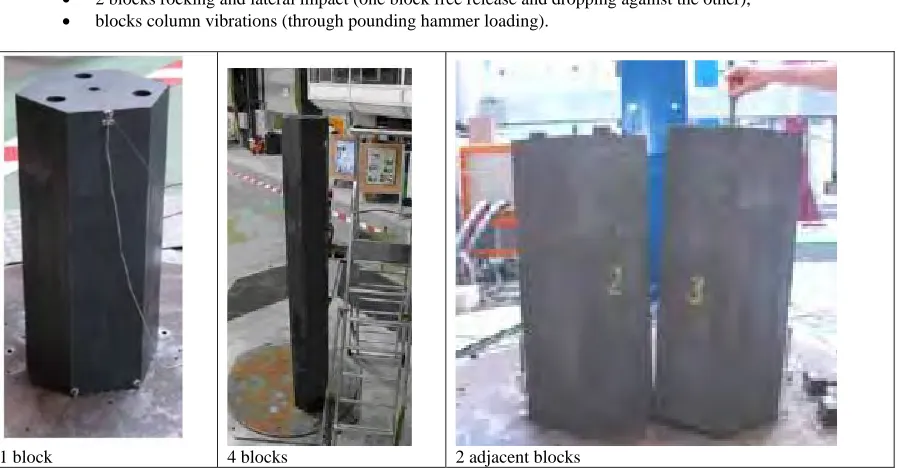
Series of experiments have been carried out in the CEA/EMSI laboratory, on a few blocks, with free release tests or dynamic tests on a shaking table. Three experiments are considered in this paper. They are used to test the numerical models and acquire the corresponding parameters (impact stiffness and damping) (Figure 3):
• single block rocking (free release),
• 2 blocks rocking and lateral impact (one block free release and dropping against the other), • blocks column vibrations (through pounding hammer loading).
For each edge : 2 contacts with the adjacent blocks, 1 contact with the up or down block.
Dowel pins contacting elements
(initial gap 1mm) Pounding in dowel
2.2 Theoretical results: interpretation of the tests
Numerical simulations were performed using the numerical methods presented in § 1. It is possible to obtain a reasonable agreement with the experimental results. The experiment allows not only the acquisition of numerical values for the parameters of the model, but also the validation of the model: the spring dampers model with Coulomb friction has a physical meaning. The dynamic behavior is characterized by two main facts:
• The impact duration is very short, at least compared with the time for rocking,
• The impacts are inelastic, with no “rebounds”: this feature can be observed for the contacts between the blocks and the soil, or for the contact between two adjacent blocks.
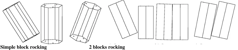
For some tests, different sets of parameters can be used to describe the experimental behaviour: a change in the impact stiffness will change the impact duration but will not change the global motion. One set of parameters has been chosen, that permits to describe the 3 tests. This set will be used for simulations on a whole core. Figure 4 represents numerical results, obtained for the one block rocking case: the initially quiescent block being tilted then released (the experimental results are very similar and are not presented). Figure 5 presents some snapshots of the block dynamic behaviour for the “one block test” and the “two adjacent blocks test”.
Figure 4 : Numerical results for a single block rocking with an initial drop angle
Simple block rocking 2 blocks rocking Figure 5 : Block dynamic behaviour
Energy (J)
• The second one is based on the development of a dedicated computer program designed for the analysis of a 2D block stack (representing a vertical slice of HTR core). Such approach is believed to be conservative compared to a 3D model and allows faster computations.
• Examples of simulations are presented in the next sections, performed by AREVA, EdF and CEA. 3.2 HTR graphite core numerical modelling
To demonstrate the ability of finite elements software to deal with a high number of non linearities including impacts between blocks and rocking motions, a 2D vertical slice of HTR core was modelled and a 20s long time history computation was performed.
The stack, which dimensions are 6.156 m x 10.400 m, consists in 17 columns of blocks. Each block is 0.36
m wide and 0.80 m high, except for the lower and upper layers, which are partly constituted of half blocks. This design corresponds to a slice of GT-MHR core (see reference [1]). There are horizontal gaps between each column: 2 mm, and the same gap is chosen between the rigid core barrel and the lateral blocks. A 1 mm clearance is considered in pin dowel systems, horizontally linking together two blocks of a same column. The whole model is reproduced on
Figure 6. Impacts between adjacent blocks, as well as rocking phenomena, are modeled by non linear visco-elastic contact elements, as illustrated on
Figure 2. In a first approximation, friction phenomena are neglected.
Simulations were performed with both SYSTUS (AREVA) and Code_Aster (EdF) software. Results were found to be in good agreement between the two software. The block stack was found to respond as a lumped mass to the dynamic solicitation as soon as the clearance between blocks is filled
Figure 7 for illustration).
Although the results obtained through FEM computer codes were satisfactory, the computation cost was found to be high because of:
- The finite elements force equilibrium computations, which are not necessary since blocks behave largely as rigid bodies.
- The need to find a time step small enough, even with implicit algorithm, for the impacts to be well modelled (prediction of contact durations, succession of collisions events) and for the high frequency vibration modes of the very rigid finite elements not to cause the divergence of the non-linear dynamics computation.
3.3 Dedicated computations
To deal with the high computation cost demanded by FEM software, a dedicated MATLAB program was developed by AREVA to speed up the computations, based on certain hypothesis:
• A 2D modelling was considered to be sufficient to represent the global behaviour of the whole stack structure.
• Each block was taken as a rigid body having only 3 degrees of freedom and a rigid body formulation of the equations of dynamics was used.
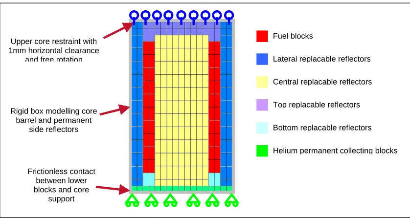
Figure 6 : Figure: 2D FEM mesh: model of a VHTR core slice.
Figure 7 : Displacements of the blocks under seismic loading (displacements and gaps x 50)
• An efficient time integration algorithm was used and the code was built so that another algorithm could be easily tested.
• Only a certain amount of data, possibly specified by the user for further statistical analysis, is stored on the disk.
The critical input parameters for the simulation include the geometrical parameters and the friction coefficient, which are easily available, but also the impact parameters: the equivalent stiffness and damping to be applied to the visco-elastic (spring-damper) elements to represent the different non linear behaviors of a block stack structure.
Fuel blocks
Lateral replacable reflectors
Central replacable reflectors
Top replacable reflectors
Bottom replacable reflectors
Helium permanent collecting blocks Rigid box modelling core
barrel and permanent side reflectors
Frictionless contact between lower blocks and core
support Upper core restraint with 1mm horizontal clearance
and free rotation
Frictionless
sliding zone
Rocking
zone
same vertical level. The system behaves as a lumped mass, as in the results presented on
Figure 7. As in the case of a few blocks, the behavior strongly depends on the relatively high damping during the impacts between the blocks: during a seismic excitation, the blocks go to one side, with an impact without rebound, stay in contact with this side, and come back later to the other side, due to the continuation of the seismic excitation.
Figure 8 : Relative velocities of one row of blocks during a seismic excitation
Figure 9 : Analysis of the absolute displacements of the blocks
Estimation can be made of the duration of the movement form one side to the other one, and of the velocity. If the seismic acceleration is
γ
and the cumulated gapsG
, the time is such thatG
=
1
/
2
γ
t
2 :t
=
2
G
/
γ
. The maximum velocity isV
=
γ
t
=
2
γ
G
. This time corresponds to a transition frequency in the dynamic behaviour of the regularly spaced block stack, as observed in previous works, see reference [4].Such estimation of the movement of the blocks (global movement with a maximum velocity mainly depending on the cumulated gaps and to the acceleration) can be used to study the control rod drop during an earthquake or the integrity of the blocks.
Velocity (m/s)
Time (s)
Cumulated gaps
Displacement of the left boundary
Displacement of the right boundary Displacement of the blocks
Numerical result displacement
time
4 Whole core experimental (project)
Experiments on a large number of blocks are in preparation in order to validate the previous analysis. Either a vertical slice or a hexagonal configuration will be considered. Due to the size of the problem, reduced scale blocks will be used.
The main objective of the tests is to verify if, in a core constituted of a large number of blocks, the impacts between the blocks are “without rebounds”, as in the tests on a few blocks. It has been seen that this hypothesis strongly influences the global behavior of the core.
5 Conclusion
The research program of EdF, AREVA and CEA on the seismic behavior of the HTR core has been presented. The experimental tests on a few blocks allow to validate the choice of numerical methods to describe the dynamic behavior of the blocks: spring dampers elements are used for the whole core finite element analysis.
The dynamic behaviour of the blocks strongly depends on the relatively high damping during the impact (with no rebounds), and also on the friction coefficient. This feature is observed in the tests with a few blocks and, in numerical simulation of the dynamic behaviour of the whole core, leads to global movements of the block stack, governed by frictional contact parameters as well as the clearance between block columns.
Experimental tests with a large number of blocks are in preparation, in order to validate the results obtained by numerical simulation on a whole core.
6 References
[1] Minatom, General Atomics, Framatome, Fuji Electric. Doc RE11.6. Reactor system design description.
GT-MHR 100002. 11/1997.
[2] Ikushima T. & al, Seismic research on block-type HTGR core, Nuclear Engineering and Design 71 (1982) pp. 195-215.
[3] Iyoku T., Futakawa M., Ishihara M. Evaluation of aseismic integrity in HTTR core-bottom structure I. Nuclear Engineering and Design, Volume 148, Issue 1, June 1994, pp. 71-81.
[4] Ahmed K.M., Parker J.V. and Proffitt D.E. Seismic response of the advanced gas cooled reactor core, Nuclear Engineering and Design, vol. 94, Issue 1, June 1986, 67-92.
[5] Ahmed K.M., Stojko S. Seismic response of the advanced gas cooled reactor core, Earthq. Eng. Struct. Dyn., vol. 15, 1987, 159-188.
[6] Cast3M. CEA. See web site: http://www-cast3m.cea.fr/cast3m/index.jsp.
[7] Code_Aster: FEM open source software, distributed under a general public license, see web site:
www.code-aster.org.
[8] Systus. ESI.
[9] Voldoire F., Greffet N., Devesa G., Aufaure M.: Algorithme non-linéaire dynamique du Code_Aster
(opérateur DYNA_NON_LINE), see: http://www.code-aster.org/DOCASTER/EDF/R5/R50505.pdf.
[10] Hilber H.M., Hughes T.J.R. and Taylor R.L.: Improved numerical dissipation for time integration
algorithms in structural dynamics. Earthq. Engng. Struct. Dyn. 5, 283-292 (1977).
[11] Ben Dhia H., Zammali Ch.: Level-Sets fields, placement and velocity based formulations of contact-impact
problems. Int. J. for Num. Meth. in Engng. Published Online: 23 Aug 2006.
![Figure 1 : experimental ant theoretical studies [2]](https://thumb-us.123doks.com/thumbv2/123dok_us/1180994.1148481/2.612.101.524.88.277/figure-experimental-ant-theoretical-studies.webp)