DIGITAL WATERMARKING AND DATA HIDING TECHNIQUES
Akram M. Zeki. Khedher & Dr. Azizah Abdul Manaf
University Technology Malaysia
Faculty of Computer Science and Information System
[email protected]
&
[email protected]
00600190640683
ABSTRACT
Watermarking is a special case of the general information hiding problem. The central idea is to robustly embed information in a medium known as the cover object in order to produce the stego object. The embedding is done in such a way that the cover and stego objects are indistinguishable.
KEYWORDS: Watermarking, Data Hiding, Watermarking Techniques.
1. Introduction
Information hiding is the addition of application oriented information to a multimedia signal without causing any perceptible distortion. The energy of the embedded signal should be low enough when projected onto the human perception domain, but it should be strong enough for robust machine detection.
2. Watermarking Requirements
With respect to the general information hiding problem, a tradeoff is involved between robustness, visibility and capacity.
2.1 Image quality
In most applications, the watermarking algorithm must embed the watermark such that this does not affect the quality of the underlying host data. The watermark is truly imperceptible if humans cannot distinguish the host data from the watermarked data. However, since users of watermarked data normally do not have access to the host data, they cannot perform this comparison. Therefore, it is sufficient that the modifications in the watermarked data go unnoticed as long as the data are not compared with the original data [1].
Perceptual coders minimize the error perceived by the human visual system (HVS). These were introduced since it was found that working with the peak signal to noise ratio (PSNR) criterion and the mean square error (MSE) criteria was inadequate in reducing perceived distortions introduced by compression [1].
A common measure for compression performance is the achieved compression ratio
the mean squared error MSE
which is the averaged term-by-term difference between the input signal (the original image, F) and the output signal (the watermarked image, F’), the signal to noise ratio
which represents the size of the error relative to the input signal – alternatively on a logarithmic scale,
in unit of decibels – or the peak signal to noise ratio (PSNR), given by
where Fpeak is the peak value of the input signal (usually
255 for 8 bit grey scale images). 2.2 Robustness
A second important requirement of watermarking schemes is robustness. Clearly a watermark is only useful if it is resistant to typical image processing operations as well as to malicious attacks. However, it is important to note that the level of robustness required varies with respect to the application at hand. These attacks can be broken down into 4 categories as proposed by Hartung in [2].
The first classes of attacks are simple attacks that do not change the geometry of the image and do not make any use of prior information about the watermark. For example these methods do not treat the watermark as noise, but assume the watermark and the host data are inseparable. Attacks in this category include filtering, JPEG and wavelet domain compression, addition of noise, quantization, digital to analog conversion, enhancement, histogram equalization, gamma correction, and printing followed by re-scanning. These attacks attempt to weaken detector response by increasing the noise relative to the watermark.
this category include the removal of pixels, or lines and columns as done in the program UnZign [3]. Even more subtle attacks are performed in the program Stirmark 3.1 [4] where the image is unnoticeably distorted locally by bending and resampling. The main goal of these attacks are to render the watermark unreadable even though it is still present in the modified image.
The third classes of attacks are ambiguity attacks. Here the aim is to create a deadlock where it is unclear which image is original. One example is the insertion of a second watermark by a pirate [5]. Craver [6] introduces the concept of noninvertible watermarking schemes and demonstrates that under certain circumstances a fake original can be created. This creates a deadlock situation in which it is impossible to determine the true owner of an image. Another attack which can be placed in this category is the copy attack [7]. Here the attacker estimates the watermark from one image and adds it to another image to produce a watermarked image.
The final classes of attacks are the Removal Attacks. In many ways these are the most sophisticated attacks since they take into account prior knowledge of the watermarking process. These attacks attempt to estimate the watermark and then remove the watermark without visible degradation to the host media. Examples are collusion attacks which attempt to get a good estimate the watermark from several watermarked images [8]. Another possibility is denoising where the watermark is modeled as noise [9]. Recently, Voloshynovsky [10] showed that it is possible in some cases to improve the quality of the image while removing the watermark. This is an important result since it demonstrates the power of denoising schemes in performing an accurate separation of watermark and host data.
2.3. Watermarking Capacity
Finally capacity refers to the amount of information we are able to insert into the image. Designing and optimizing information hiding algorithms involves the delicate process of judiciously trading off between these three conflicting requirements [1].
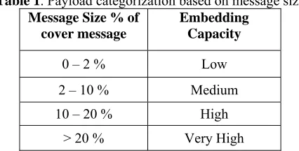
Under the present day scenario a rough estimate of low, medium and high payload, particularly for images, is shown in Table 1.
Table 1. Payload categorization based on message size Message Size % of
cover message
Embedding Capacity
0 – 2 % Low
2 – 10 % Medium
10 – 20 % High
> 20 % Very High
3. Watermarking Techniques
In general, watermark can be embedded in spatial domain or transform domain of an image. In the spatial domain approach the pixel value of an image is
modified to embed watermark information. The spatial techniques insert the watermark in the underused least significant bits of the image. This allows a watermark to be inserted in an image without affecting the value of the image [11].
There are many variants of spatial domain techniques. They essentially involve embedding the watermark by replacing the least significant bit(s) of the image data with a bit(s) of the watermark data. The human visual system HVS is insensitive to the value change in these areas. Thus, we can use these areas to embed messages. Generally speaking, the more significant bit-plane the noise area appears in, the larger variation of grey values among the neighboring pixels there will be, and then more bits could be used to embed messages. So, the first step is based on the grey value variation of neighboring pixels to compute the number of embedding bits for each pixel [12].
The simplest example of a spatial domain watermarking techniques to insert data into digital signals in noise-free environments is least significant bit (LSB) coding. There are many variants of this technique. It essentially involves embedding the watermark by replacing the least significant bit of the image data with a bit of the watermark data [13].
The most straightforward way to embed a watermark into an image in the spatial is to add a pseudo random noise pattern to the luminance values of its pixels. Schyndel, [13] proposed a method based on bit plane manipulation of the least significant bit (LSB) which offers easy and rapid decoding. Macq, inserts the watermark into LSB only around image contours [14]. Caronmi hides small geometric patterns called tags in regions where the tags would be least visible, such as the very bright, very dark or texture regions [15]. Bender, choose random pairs of image points and increase the brightness of one and decrease that of the other [16]. Nikolaidis, add a small positive number to random locations as specified by the binary watermark pattern and use statistical hypothesis testing to detect the presence of watermark [17]. Voyatzis, use dynamic systems to generate chaotic orbits which are dense in the spatial domain and hide the watermark at the seemingly chaotic locations [18].
4. Methodology
In this approach, analysis of the original host image will be made in order to classify the regions of the image. This classification of regions is for the sake of different treatment of data hiding strategy in each different region. The second step is the selection of the sequence of data hiding which will be chosen to embed data within the original image.
embedded in each block is decided by the suitability embedding block and from pixel to another pixel as will be shown in the next section. The sequence of data hiding shall be carefully selected and inherited into the key which will be inherited into the program used for recovering the hidden watermark later.
The embedding process will use a key for hiding data. The same key will be used for restoring of hidden data. In order to resist changes like lossy compression, etc.., the use of some redundancy in hidden data may be necessary to ensure impossible deletion of important parts of the watermark. Attempts for increasing the amount of hidden data, and then evaluation of quality of picture noise and noise recognition by naked eye has to be made. Figure 1 shows the approach of embedding watermarking.
End
Analysis of picture and classifying regions
Selection of sequence of data
hiding
Embedding Testing of data
Robustness aspect of the digital image
Increasing the amount of hidden
data
Evaluation of quality of picture
noise
Comparing the result of capacity & robustness with other results
Figure 1. Analysis of picture and classifying regions
The host image will be partitioned into non overlapping blocks, each block contains n x m pixels. Consider a block of 3 x 3, as shown in Figure 2.
Figure 2 Portioning the picture into 3 x 3 blocks.
After partitioning the image into blocks and presenting each pixel as decimal (0 – 255), 3 pixels for each block will receive special treatment. Referring to Figure 3 (Pmax the maximum point’s value with (x1, y1)
coordinator, Pmin the minimum point’s value with (x2,
y2) coordinator, and Pmid which is the furthest point
from Pmax & Pmin, with (x3, y3) coordinator.
The furthest point will be found according to the distance between from the two previous points ( Pmax
and Pmin) i.e. if (x1, y1 = 1, 1) & (x2, y2 = 3, 1) then
(x3, y3) =2, 3), while (x1, y1 = 2, 1) & (x2, y2 = 1, 2) then (x3, y3) =3, 3). The third point (Pmid) coordinates
could be found also by a suitable look up table.
50 30 100
199 70 66
45 144 90
Figure 3. Finding the maximum point (2,1), minimum point (1,2) and the third point (3,3)
The first step for embedding information, modifying the max point Pmax to P`max ((the lowest (n x 16 - 1) greater
than Pmax, this rage table design by user) (n = 1:15). i.e.
P`max = 15, 31, 47, 63, 79, 95, 111, 127, 143, 159, 175,
191, 207, 223, 239, and 255. And modifying the Pmin to
P`min (the highest (n x 16) less than Pmin) (n = 1:15). i.e.
P`min = 0, 16, 32, 48, 64, 80, 96, 112, 128, 144, 160,
176, 192, 208, 224, and 240. Start
The embedding module will be applied to each block from left to right and from top to bottom in the image sequentially, and for each block (9 pixels - 3 x 3 ), the max, min and the third points will be found, i.e. Pmax,
Pmin and Pmid. The other 6 pixels P1, P2, …. P6, will be
addressed from left to right and from top to bottom in an image sequentially, Figure 3.4 will be presented again in Figure 4 as shown below:
P1 Pmin P2
Pmax P3 P4
P5 P6 Pmid
Figure 4. Addressing the 9 pixels
The regions of the pictures will be divided into at least 3 types of locations by discrete logic relations (or by fuzzy logic if found appropriate), the following are guide lines for the selection of the three regions:
1. Shallow changed data locations (Pmax - Pmin <
16), where we can hide few bits only, at the least significant bits e.g.
120 122 126 121 118 123 122 119 117
2. Nearly linearly changed data locations ( Pmax -
Pmin => 16 and (P1+P2+P3+P4+P5+P6) / 6 ≈
according to the method we shall describe later) e.g.
060 120 180 090 151 212 118 183 244
3. Locations with sharp changes ( Pmax - Pmin =>
16 and (P1+P2+P3+P4+P5+P6) / 6 far a way
from the two pixels average (Pmax - Pmin) / 2 ),
we can hide important data ( possibly high value bits of the watermark or hiding commands which directs the flow of the program ) in the edges because the expectation of changes by lossy compression is low) e.g.
033 050 185 046 154 077 120 066 043
5. Results and Discussion
In this example we will embed UTM logo into cover image, both of them must convert to grey scale image first, then our proposed method will be applied as shown in Figure 5.
Original images grey scale image Watermarking image
+
Figure 5. Embedding UTM logo into cover image.
The above UTM logo contains 100 x 100 pixels (about 10 Kilo bytes) has been embedded into the cover image which is contains 200 x 200 pixels (about 40 Kilo bytes). The ratio capacity of embedding data from cover image is about 25 % and the peak signal to noise ratio of watermarking image after embedding is 31.9 dB. The above steps will be applied to all blocks from right to left and top to button, The capacity of embedding = number of bytes of data hiding / number of bytes of cover image x 100 % = 10000 / 40000 = 25 %. To study the image quality of watermarking image or the peak signal to noise ratio (PSNR), given by
where Fpeak is the peak value of the input signal (in this
example 255). The peak signal to noise ratio in above
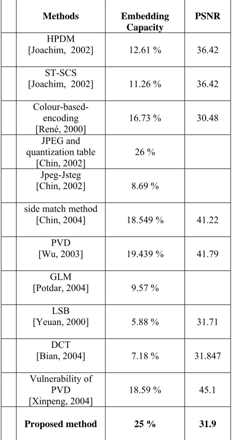
example is 31.9 dB. To compare the result of the proposed method with some other methods, as shown in table 2.
Table 2 Comparison between embedding capacity
Methods Embedding Capacity
PSNR
HPDM
[Joachim, 2002] 12.61 % 36.42 ST-SCS
[Joachim, 2002] 11.26 % 36.42
Colour-based-encoding
[René, 2000] 16.73 % 30.48 JPEG and
quantization table
[Chin, 2002] 26 % Jpeg-Jsteg
[Chin, 2002] 8.69 % side match method
[Chin, 2004] 18.549 % 41.22 PVD
[Wu, 2003] 19.439 % 41.79 GLM
[Potdar, 2004] 9.57 % LSB
[Yeuan, 2000] 5.88 % 31.71 DCT
[Bian, 2004] 7.18 % 31.847 Vulnerability of
PVD
[Xinpeng, 2004] 18.59 % 45.1 Proposed method 25 % 31.9
Regarding the robustness few attacks have
been applied in order to study the robustness
of least significant bits method, first figure 6
has been embedded into the host image by
spatial domain technique starting from least
significant bits LSB to most significant bits
MSB (8
thbits, 7
thbits, 6
thbits, 5
thbits, 4
thbits,
3
rdbits, 2
ndbits, 1
stbits), as shown in table 3.
Table 3. few attacks have been applied for spatial domain embedding (LSB to MSB) Attacks 8th Bit LSB BCR PSNR
jpg'90 67.9400 58.9645
jpg'70 67.7333 46.9013
jpg'50 61.4533 45.1614
median 83.8667 44.4346
wiener 68.0333 48.1415
Salt &
pepper 97.5067 32.2036
Gaussian 67.6467 32.7131
Attacks 7th Bit LSB BCR PSNR
jpg'90 68.8333 54.6137
jpg'70 67.9600 46.5068
jpg'50 67.8600 44.9868
median 85.6867 44.2389
wiener 68.6467 47.8046
salt &
pepper 97.7200 32.5363
Gaussian 67.5933 32.5952
Attacks 6th Bit LSB BCR PSNR
jpg'90 71.0733 48.9707
jpg'70 69.1933 45.0922
jpg'50 69.0400 43.9161
median 88.2600 3.4603
wiener 70.5467 46.4765
salt & pepper
97.5933 31.5615
Gaussian 67.6133 32.4648
Attacks 5th Bit LSB BCR PSNR
jpg'90 74.7800 42.6950
jpg'70 70.7400 41.6075
jpg'50 70.2200 41.2748
median 90.5800 41.0893
wiener 71.9200 43.0612
salt & pepper
97.4867 31.4044
Gaussian 67.5933 32.2278
Attacks 4th Bit LSB BCR PSNR
jpg'90 79.9133 36.4666
jpg'70 73.3267 36.3317
jpg'50 71.7867 36.3839
median 92.8733 36.4663
wiener 73.6333 37.6513
salt & pepper
97.3600 30.6293
Gaussian 67.6400 31.2176
Attacks 3rd Bit LSB BCR PSNR
jpg'90 86.7733 30.7534
jpg'70 79.1000 30.7163
jpg'50 76.2600 30.6765
median 93.8933 30.9610
wiener 75.1867 31.8479
salt &
pepper 97.2133 28.2822
Gaussian 68.5267 28.5971
Attacks 2nd Bit LSB BCR PSNR
jpg'90 90.2467 23.9993
jpg'70 84.0867 23.9827
jpg'50 81.5800 24.0286
median 96.8000 24.1733
wiener 81.2400 24.6686
salt &
pepper 97.4867 23.4181
Gaussian 72.5800 23.5841
Attacks 1st Bit LSB BCR PSNR
jpg'90 98.9000 18.5072
jpg'70 97.4400 18.5260
jpg'50 97.0067 18.5354
median 99.1133 18.5920
wiener 95.5733 18.9870
salt &
pepper 97.6000 18.3987
6. Conclusion
The aim of this study is to develop an intelligent watermarking model by spatial domain technique, which can find out the possibility to hide maximum amount of data in an image without degrading the quality of the host image and at the same time the watermarked picture should be robust and survive any compression and difficult to be removed from the original picture.
In this approach, analysis of the original host image has been done in order to classify the regions of the image. This classification of regions is for the sake of different treatment of data hiding strategy in each different region. The second step is the selection of the sequence of data hiding to embed data within the original image. The embedding process has been divided into 3 types of locations by discrete logic relations (or by fuzzy logic if found appropriate). The three regions are: Shallow changed data locations, Nearly linearly changed and Locations with sharp changes. The first and second types have been shown here, and random text data as well as pictures have been embedded within the cover image and the result shows that the embedding capacity was 25 % while the peak signal to noise ratio was 31.9 dB.
Regarding the robustness few attacks have
been applied in order to study the robustness
of least significant bits method, spatial domain
technique has been used for this study starting
from least significant bits LSB to most
significant bits MSB (8
thbits, 7
thbits, 6
thbits,
5
thbits, 4
thbits, 3
rdbits, 2
ndbits, 1
stbits).
References
1. Shelby P. Robust Digital Image Watermarking, PhD thesis, University of Geneve, Faculty of Science, Canada. 2000.
2. Hartung, F. Su, J. K. and Girod. B. Spread spectrum watermarking: Malicious attacks and counterattacks. In Proc. SPIE Security and Watermarking of Multimedia Contents 99, San Jose, CA., January 1999.
3. Unzign watermark removal software. Technical report http://altern.org/watermark/ , July 1997. 4. Petitcolas, F.A.P.; Anderson, R.J.; Kuhn, M.G.
Information Hiding-A survey", Proceedings of the IEEE, Volume: 87 Issue: 7 , Page(s): 1062 -1078. 1999.
5. Holliman M. and Memon. N. Counterfeiting attacks on linear watermarking systems. In Proc. IEEE Multimedia Systems 98, Workshop on Security Issues in Multimedia Systems, Austin, Texas, June 1998.
6. Craver, S. Memon, N. Yeo, B. L. and Yeung, M. M. Resolving rightful ownership with invisible watermarking techniques. IEEE J. Selec. Areas
Communic. (Special Issue on Copyright and Piracy Protection), 16:573 586, May 1998.
7. Hilton, D. Method of and apparatus for manipulating digital data works. International Publication number WO 96/27259, september 1996.
8. Stone, H. S. Analysis of attacks on image watermarks with randomized coefficients. Technical report, NEC Res. Inst., Princeton, New Jersey, May 1996.
9. Langelaar, G. C. Lagendijk, R. L. and Biemond, J. Removing spatial spread spectrum watermarks by non-linear ltering. In Proc. Europ. Signal Processing. Conf. (EUSIPCO 98), Rhodes, Greece, Sept. 1998.
10. Voloshynovskiy, S. Deguillaume, F. Pereira, S. and Pun, T. Optimal Adaptive Diversity Watermarking with Channel State Estimation. Proc. SPIE: Security and Watermarking of Multimedia Contents III, 4314(74). 2001.
11. Azizah, A. M., Akram, M. Z., Sayuthi, J., Watermarking of Digital Images: An Overview, 2nd National Conference on Computer Graphics & Multimedia. Malaysia. 2004.
12. Yeuan, K. L. and Ling, H C. High capacity image steganographic model. IEE Proc.-Vis. Image Signal Process., Vol. 147, No. 3, June 2000
13. Schyndel, V. R.G.; Tirkel, A.Z.; Osborne, C.F. A digital watermark”, Image Processing, 1994. Proceedings. ICIP-94. IEEE International Conference, Volume 2 , 1994 Page(s): 86 -90 vol.2. 1994.
14. Macq, B. M. Quisquater, J. J. Cryptology for Digital TV Broadcasting. Proc. of the IEEE, vol. 83, no. 6, pp. 944-957, Jun 1995.
15. Caronni, G. Assuring Ownership Rights for Digital Images, Proc. of Reliable IT Systems. 1995.
16. Bender, W. Gruhl, D. Morimoto N. and Lu, A. Techniques for Data Hiding. IBM System Journal, vol. 35, NOS 3&4, pp. 313-336, 1996.
17. Nikolaidis, N. Pitas, I. Copyright Protection of Images using Robust Digital Signatures. in Proc. of, IEEE Int. Conf. on Acoustics, Speech, Signal Processing, vol. 4, pp. 2168-2171. 1996.