ABSTRACT
PLACE, THOMAS JEFFERSON. BATMAV: A Biologically-Inspired Micro Air Vehicle for Flapping Flight – Design and Fabrication of Skeleton Structure and Wing Membrane. (Under the direction of Stefan Seelecke.)
The purpose of this research has been to design and construct a durable, capable micro-aerial-vehicle structure. The motivation for the design theme are the naturally occurring non-rigid wing structures such as those seen in bats, due to their inherent agility, adaptability, and relatively low flapping frequency. Bat skeleton measurements were taken and modeled in SolidWorks to accurately reproduce bones and body via rapid prototyping machines. The superelastic qualities of SMA wires are the enabling technology for connecting joints that require large rotational ranges without the fatigue and plastic
by
Thomas Jefferson Place
A thesis submitted to the Graduate Faculty of North Carolina State University
in partial fulfillment of the requirements for the Degree of
Master of Science
Mechanical Engineering
Raleigh, North Carolina 2007
APPROVED BY:
____________________________ ____________________________ Dr. Ashok Gopalarathnam Dr. Gregory D. Buckner
____________________________ Dr. Stefan Seelecke
BIOGRAPHY
ACKNOWLEDGMENTS
TABLE OF CONTENTS
LIST OF TABLES ... vi
LIST OF FIGURES ... vii
1. INTRODUCTION ... 1
2. MOTIVATION FOR RESEARCH INTO BAT-LIKE MICROAIRCRAFT ... 2
3. OBJECTIVES ... 7
3.1 Range Of Motion ... 8
3.2 Bone Strength ... 8
3.3 Joint Flexibility and Strength ... 8
3.4 Scale ... 9
3.5 Membrane ... 9
4. PREVIOUS STATE-OF-THE-ART ... 10
4.1 MAV Research and Development ... 10
4.2 Bat Kinematics ... 14
4.3 Bat Physiology ... 16
5. MATERIALS AND METHODS ... 19
5.1 SolidWorks Model ... 19
5.2 Rapid Prototyping ... 20
5.3 Smart Materials ... 20
5.4 Wing Membrane ... 24
5.5 Initial Design ... 25
5.5.1 Skeleton ... 25
5.5.2 Membrane ... 28
5.5.3 Full Assembly ... 30
5.6 Skeleton Final Design ... 32
5.6.1 Motivation for Materials ... 32
5.6.2 Features and Construction ... 34
5.6.3 Comparative Results ... 38
5.7 Membrane Material Study ... 44
5.7.2 Production and Attachment Methods ... 46
5.7.3 Testing Procedure and Results ... 48
5.7.4 Conclusion and Recommendations ... 53
6. RESULTS AND CONCLUSIONS ... 55
6.1 Process Approach ... 55
6.2 SolidWorks Bone Structure ... 56
6.3 Rapid Prototyping ... 56
6.4 Skeleton Assembly ... 57
6.5 Membrane ... 58
6.6 Overall Structure Performance ... 59
7. DISCUSSION OF RELEVANCE ... 60
8. RECOMMENDATIONS FOR FUTURE RESEARCH ... 62
LIST OF TABLES
Table 1 Critical BATMAV Dimensions... 44
Table 2 Hysteretic stretch behavior... 49
Table 3 Strain decay over time for single load... 50
Table 4 Stress-strain curves over time... 51
Table 5 Olive oil coated sample stress-strain curves over time ... 52
LIST OF FIGURES
PREVIOUS STATE-OF-THE-ART
Figures 1-2. MAV development at Notre Dame [1]... 10
Figures 3-4. The Black Widow designed by Darpa and Aerovironment ... 11
Figure 5. The University of Florida's semi-rigid wing MAV ... 12
Figure 6. Beginning of the downstroke. The tail and feet are held straight backwards. Long-eared bat Plecotus auritus in slow horizontal flight, Norberg et al. (1993) ... 14
Figure 7. Middle of the downstroke. The twisting of the wings is clearly seen in the upper photograph. ... 15
Figure 8. Later part of the downstroke. The wings are sharply cambered, and the tail membrane is fully lowered... 15
Figure 9. Beginning of the upstroke. The elbows and wrists are slightly flexed. The camber is still pronounced ... 15
Figure 10. Later part of the upstroke. The feet are raised which reduces the camber of the proximal part of the wings. The middle part is still cambered, but the wing tips are momentarily inverted ... 16
Figure 11. Plan-view of the ventral surface of the wing for a Plecotus auritus [15] ... 17
Figures 12-14. Elastic blood vessels and wrinkled texture of wing membrane in a small Brown Bat (myotis lucifugus)... 18
MATERIALS AND METHODS Figure 1. Knutson’s first phase model in SolidWorks ... 19
Figure 2. Stress-Strain comparison of SMA to spring steel... 21
Figure 3. Euler-Bernoulli beam analysis of SMA joint wires [17]... 22
Figures 4-5. Simple single-wire joint between humerus and radius bones ... 24
Figure 6. SLA epoxy produced body and arm bones ... 26
Figures 7-8. Puncturing membrane with 500-micron wire with negligible observed Propagation ... 28
Figure 9. This membrane cast between milled aluminum plates... 29
Figure 10. First iteration full assembly (“the headless wonder”) ... 31
Figure 12. First phase body design (left) compared to improved second phase (right) ... 33
Figure 13. ABS plastic via 3-D printing (left) versus SLA epoxy body (right) ... 34
Figure 14. SolidWorks model without 500-micron SMA wire finger bones... 34
Figure 15. Diagram of 1- and 2-wire joints... 35
Figure 16. Characterized motion of 2-wire joints... 35
Figure 17. Wing-stroke plane... 36
Figure 18. Assembly of 2-wire joint with JB Weld steel epoxy... 37
Figure 19. Natural camber and angle due to joints when extending the wing... 38
Figures 20-21. Second iteration skeleton laying on flat surface (left) and dangling (right) ... 39
Figures 22-23. Third iteration skeleton laying on flat surface (left) and dangling (right) ... 39
Figure 24. Body locking tab after acetone treatment (left) and without (right)... 40
Figure 25. Body texture after acetone treatment (left) and without (right)... 40
Figures 26-27. 2-wire joint (left) and full final assembly (right)... 41
Figures 28. Fully assembled 6.3g BATMAV with membrane during attachment curing... 42
Figures 29. 9.3g Brown Bat with left wing extended... 42
Figures 30. Fully assembled BATMAV Skeleton... 43
Figures 31. X-ray photograph of bat [20] ... 43
Figures 31-32. Stress-strain curves for typical rubber and animal tissue [18]... 45
Figure 33. Membrane attached using molten gelatin resin and injection needle... 47
Figure 34. Membrane Force-Deflection Testing Rig ... 48
Advancement among micro-aerial vehicle (MAV) design has been slow over the past several years due to the lack of true understanding of aerodynamics, materials, and scale. Most MAVs are used in surveillance applications of some kind, be it flying into a dark, unknown cave location or into the fiercest winds of natural storms. Currently several universities have research centers in this field such as the Notre Dame MAV Development Group [1] and the Center for MAV Research at the University of Florida [2].
To this point, there have been many design themes implemented, from the scaling down of current and tested airplane structures like the “Black Widow” developed by DARPA [3], to the mechanical flapping of insect-like ornithopter toys like the FlyTech DragonFly [4] even commercially available at Radio Shack. While many have been successful and long-standing flyers, all have their flaws. Rigid-wing pucks with props have the advantage of larger
cavities for storage and sensors, but poor agility and unstable performance in inclement weather with unbridled, shrill propeller noise; rigid-wing flappers can be made smaller and thus more agile, but sacrifice sensor capacity for a large, rotating mechanical system of links.
Presently, Dr. Kenneth Breuer is directing research in mammalian flapping flight at Brown University [5]. The dynamics of wing shape and propulsion aerodynamics is being
deciphered to figure out exactly how certain creatures can fly and hover so easily through high winds and constricted environments. The main motivation for such research has to do with nature’s tendency to evolve and to optimize systems.
mostly skin and bone, giving it favorable mechanical parameters. It is easy to pick up a bat and see all the working parts and pieces without dissection or removal of feathers.
Essentially, the bat exhibits many of the key flying attributes that basic MAV designs sorely need.
The goal of this project is to develop a bat-like micro-aerial vehicle (BATMAV) using rapid-prototyping technology and smart materials. A biomechanical muscle system will control and monitor the wing motion and position via electrical control of NiTi shape memory alloy wires. This thesis will focus principally on the passive mechanical structure of the
BATMAV through the following steps:
1. Development of SolidWorks™ model of skeleton 2. Three-dimensional printing of model in ABS plastic 3. Construction of skeleton employing shape memory wires 4. Beginning material study for membrane
2. MOTIVATION FOR RESEARCH OF BAT-LIKE
MICROAIRCRAFT
Demand for superior intelligence gathering techniques has increased in the past decade and the majority of micro-aircraft are designed with this specific goal in mind. The Defense Advanced Research Projects Agency (DARPA) has an explicit program for the development of flight enabling technologies in aircraft less than six inches in any dimension and has been working to that end since the early 1990s [7]. Research in flapping flight is a relatively new idea in this field however and can offer advantages over traditional micro-aerial vehicles.
work conducted by Murphy, Stover, Pratt, and Griffin validated the use of MAV technology in autonomous disaster response missions [8]. Nine years ago competitions were held for micro planes to enter inaccessible areas after tornado damage in Gainesville, Florida. Entrants weighed in at just over half a pound with 12-inch wingspans. Designs here consisted almost exclusively of scaled down airplane structures with props [9]. Since then sizes have been cut in half to under 6 inches with on-board sensors and cameras with extremely high resolution.
University researchers are focusing on the flight dynamics of MAVs as compared to typical passenger aircraft. The University of Florida has accurately modeled rigid-wing designs and found similar modal properties, but some that much more unstable due to the vehicle’s small size and low traveling speeds [10]. The heavier an object is, the less dramatically they are affected by wind gusts. Such light aircraft have to find some other way to handle rapid density changes and swirling wind loads. Adaptable non-rigid wing structures can provide that extra bit of flexibility and agility when facing such forces.
Typically non-rigid wings are not used with propeller or jet propulsion, but rather they are exhibited in nature in creatures that flap their wings to create lift and propel them. The only current products that employ such a flight method are ornithopters; designs with passively-flexing wings. This means that mechanical linkages are used to create flapping motion and the wings themselves are often still rigid, and if they do flex, only do so in a manner
uncontrolled by the system of linkages.
Current MAV designs are hindered by excessive noise. Most of the noise developed by a plane comes from the propeller, not the engine itself which can be damped fairly efficiently. Jet turbines produce a massive amount of noise themselves, but even in our most
maneuverable craft to date, the helicopter, more noise is introduced by the spinning blades and supersonic effects at the tips required to create the necessary lift and thrust. That noise is one of the only reasons that the helicopter is not used more widely, particularly in military applications where stealth is needed, because the noise simply cannot be hidden. Flapping wings produce very little noise when actually flapping due to the lower tip speeds, they have the ability to glide if necessary, and they can be driven with an electrical system that can be totally silent.
Combining existing features with new research fields can lead to a MAV concept that
exhibits few limitations and several desirable qualities. For example, such a design can have:
• Ten inch wingspan, collapsable into an object only 2 inches wide • Adjustable camber and pitch of its wings to maintain stability • Ability to turn abruptly and hover in tight spaces
• Simple base structure that is durable and easy to construct and tune
The decision to use a bat as the design to mimic with this project is motivated by the presence of the aforementioned features without complicated physical features such as the feathers and flesh of birds or the size and weight of insects.
Performance-wise, bats are extremely agile and have a relatively low flapping frequency, which can reduce strain on moving components of a MAV.
Compared to rigid-wing MAVs a bat-like design has considerable stability advantages. Since the scale of such aircraft is so small the flight dynamics are drastically different from larger passenger vehicles. For example, in a commuter plane the ride is smoother and more stable the heavier the plane is because small changes in wind speed and direction on different areas of the wing and body don’t have the mass or momentum to quickly affect it. Also, to get the large mass airborne much higher flight speeds are a necessity. Smaller craft however, travel at much lower speeds, meaning even slight wind gusts can take a 20 mph headwind and turn it into a tail wind that effectively cancels traveling speed. The result with a rigid wing aircraft is the loss of lift, resulting in a loss of control since it is reliant on airflow across the wings. With a flapping wing system, the vehicle can glide under higher headwinds, or create its own lift by flapping when necessary, or flap to propel itself forward when extra lift is not necessary. In the even of a strong crosswind or upward gust a light, rigid-wing craft can be tossed into a spin creating significantly unstable modes. Flappers have the advantage of controlling each wing independently and pitch one up or in to prevent significant roll or yaw, maintaining stable course.
Furthermore, should a small plane encounter a loss of control and enter a downward spin, it takes significant velocity, time, and thus space to correct and pull up. Bats have a turning radius of less than three wing beats, meaning any loss of stability or complete control can be corrected almost immediately and in very confined areas [5]. In the event of a landing of any kind a plane requires some distance with which to pick up speed to create lift, while several species of bats can simply drop from a ledge or leap slightly to take off without a runway. If properly designed and managed, the performance advantages here alone could make the most inconceivable areas possible to explore and navigate.
muscles that are relatively simple in how they are routed to achieve specific directional motion, the difficulty presenting itself in scale and method. Where ornithoper-based flyers have mechanical linkages and rigid frames to resists deflection from loading, a bat’s wing must rely on these tendons with natural restrictive structure at joints to create the flapping movements, as well as hold the shape of the wing for proper lift and propulsion. The decision to employ shape memory alloys was made for this reason.
Shape memory alloys (SMAs) are unique materials that exhibit several mechanical advantages over traditional spring steel and like materials. In this case, 50/50 Nickel-Titanium alloy wires respond to a temperature change that induces a strain along the wire length, effectively turning it into a very efficient linear actuator. Wires can be routed in such a way that even a small amount of strain, in the range of 4%, can create enough torque around a joint to extend a wing, create camber on the leading edge, or fold on the upstroke to reduce drag. Since the wires are conductive, the temperature change can be correlated to a specific strain to be produced fairly precisely by running a controlled current through a looped wire. A system of wires can function as a biomechanical system of muscles via a sophisticated power source and electrical controller. Advantages of SMAs for this application include:
• Extremely light weight
• Highest work output from a significantly less complex linear actuator • Enable replication of tendons for bio-inspired flapping flight
• Superelastic characteristic resists plastic deformation and fatigue
that other creatures can't…We want to understand bat flight and be able to incorporate some of the features of bat flight into an engineered vehicle" [10]. The BATMAV project is creating the basis for exactly that: an engineered flying vehicle that mimics bat flight dynamics.
3. OBJECTIVES
Based on the previous motivation, the Adaptive Structures Lab at North Carolina State University started the BATMAV project with the objective of building a bat-inspired micro-aerial vehicle platform, which will enable a deeper understanding of flapping flight
mechanics. In the first stages, BATMAV will develop a desktop model that will allow us to study the effect of various flapping patterns on thrust and lift forces. The vision, of course, is to develop a version of the BATMAV that will be able to fly, but this will most likely some years into the future.
The BATMAV project as a whole consists of four major stages of development:
1. Skeletal Structure 2. Wing Membrane
3. Biomechanical Muscle System 4. Electrical Control Network
decipher the dynamic motions and muscle movements to create a power source and control architecture capable of actually flying the bat.
This thesis research will focus on the passive mechanical structure, developing the first stage and laying the foundation for future completion of the second stage of membrane design.
3.1 Range of Motion
In order for the BATMAV to exhibit similar flapping and agility characteristics there must be an established range of motion. Background research into the particular flapping paths and angles of real bats will dictate those limits. For example, while we may be able to easily create joints that are more flexible than a real bat, it may not enhance our abilities, and may in fact require other features to work harder to overcome the looseness. Therefore, one goal will be to create a system of joints that allows a comparable range of motion in specific directions.
3.2 Bone Strength
As far the bones themselves are concerned, the artificial components must be at least as strong in bending and compression as real bones. The larger bones in the wings and legs do not exhibit bending in flight from wind loading and they certainly do not break, so it would seem that artificial bone material cannot be too strong. Fingers and smaller bones will need to be more flexible and possibly require a different material all together due to their small diameter reaching the effective limit of resolution of rapid prototyping machines. Together, the bone structure must be strong enough to endure the forces induced upon it during flight.
3.3 Joint Flexibility and Strength
be more elastic than brittle, and the body itself is sturdy. In order to properly mimic a bat it cannot simply perform well in laboratory conditions. The vehicle must be able to withstand swirling winds, simple handling, and reasonable impacts. While the focus is not to make a bulletproof army of biomechanical bats, those examining and handling its articulate structure should be equally impressed with its durability.
3.4 Scale
Since BATMAV is based on a real bat, the dimensions will be determined as such and result in a roughly ten-inch wingspan. A bat-like structure allows for unique characteristics that are worthy of unique classification, such as the ability to collapse the entire wing structure. Upon doing so the entire vehicle would be no more than three inches in any given direction, with just over an inch of width, and less than an inch of depth. Such size opens the door for firing deployment into the atmosphere inside a sabot or egg-like structure for precise release points and conserving on-board energy.
3.5 Membrane
4. PREVIOUS STATE-OF-THE-ART
4.1 MAV Research and Development
Flight has always been an emotional journey for man, more than just a challenge for great builders and thinkers. Micro-aerial vehicle research and development has exploded in the past 15 years due to the ever-decreasing size of advanced technology and the desire for smaller, sexier flying craft. Currently studies are being conducted in the flight dynamics of not just rigid-wing aircraft, but flappers as well. Until we can accurately test or completely understand either one designs will not succeed to their full potential. Most in the field of MAV development shrink time-tested airplane designs and make modifications as necessary, yielding many familiar shapes such as those depicted in this paper.
Figures 1-2: MAV development at Notre Dame [1]
As of 2004, the benchmark in the state-of-the-art of MAV design was set by the Black Widow, developed by Aerovironment and Darpa. The four years or research resulted in a 6-inch wingspan, 56 gram plane with a flight range of 1.8 kilometers, flight time of 30 minutes, and maximum altitude of 769 feet while carrying a surveillance camera. As shown below [13], the vehicle is a simple, almost plate-like craft with a propeller. The effectiveness of this aircraft heralded a new level of performance goals in MAV design and led to a greater
Figures 3-4: The Black Widow designed by Darpa and Aerovironment [13]
Figure 5: The University of Florida's semi-rigid wing MAV [12]
Ornithopter craft has been one of the longest standing design goals since it was one of the earliest conceivable forms of flight from before propellers and jet engines existed. The bulk of the small flappers have tiny DC electric motors that drive a simple mechanical linkage to flap the semi-rigid wings at a certain frequency, controlled easily by motor speed. There are successful designs ranging from the 28-meter wingspan Karura of Japan [15] down to the 16-inch span FlyTech Dragonfly [4].
While they are flappers, any proven designs employ semi-rigid designs, where the wing structures themselves are still rigid, but are able to move and pitch during the up- and down-strokes. Furthermore, the wing pairs are operated in parallel to ensure there is no lopsided drag or propulsion. This feature means that sudden gusts of wind cannot be accounted for independently and often result in loss of stability. And while the turning radius is
One of several reasons flapping flyers aren’t being designed more often is the simple fact that we still do not adequately understand the dynamics of small flying craft, much less flapping flight. Brown University is at the forefront of progress in the field with their Visualization Research Lab. Wind tunnels and wire stream smoke are used to create wind vectors across the bat membrane and recorded meticulously to create a three-dimensional model of resultant forces. These models provide great insight into where exactly the forces critical to flight are generated and how [12].
With continuing research efforts and future partnership the development of a flapping flight model for a system of muscles is no longer a dream, but a milestone. The BATMAV project goal is not to decipher the aerodynamic characteristics of bats. If we can construct a passive structure that exhibits the same physical abilities and durability as a real bat, then the system should be able to handle forces inflicted on it during flight with room for fine aerodynamic tuning in the latter stages. Thus, the focus of this project will be to accurately reproduce a naturally occurring bat from inexpensive, durable manmade materials.
Once the structure is derived the actuatoric application of SMA wires can be applied to make this creature fly. The idea behind the technology is that SMAs react to heat and since they are conductive, electric current can be used to create and accurately control heat in the wire. Basically, when experiencing an electric current the wires will rapidly heat up due to their small diameter and conversely contract, up to about 8% of their total length, due to a molecular state change. During this mode of operation, the wires essentially become
capable of monitoring and actuating the SMA muscle system. The technology exists and it works, now it must be applied.
4.2 Bat Kinematics
First, the basic motions of bat flight must be understood. The critical motions in forward flight rely heavily on camber in the wing. For example, during the downstroke the wing creates a parachute-type form to help create lift. The upstroke involves some pulling in and folding of the wing to reduce drag, while using a slight snapping motion backward to create forward thrust. Unlike a rigid-wing ornithopter that involves flapping with passive camber changes, the bat exhibits some very complex motions that require an extensive system of muscles and tendons working in harmony. The result from the lightweight frame is a very efficient process operating around 10Hz maximum flapping frequency for the size species modeled in this project. For more details, Bunget has worked to create a more in-depth kinematics model for main cycles of flight in the up- and down-strokes [6].
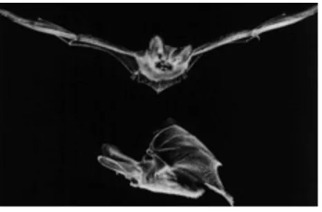
Figure 7:Middle of the downstroke. The twisting of the wings is clearly seen in the upper photograph.
Figure 8:Later part of the downstroke.The wings are sharply cambered, and the tail membrane is fully lowered.
Figure 10: Later part of the upstroke. The feet are raised which reduces the camber of the proximal part of the wings. The middle part is still cambered, but the wing tips are momentarily inverted.
4.3 Bat Physiology
In terms of complexity, bats have relatively simple body structures with respect to their passive construction. Exterior observation reveals the majority of essential, functional components without excavation. The bone structure in the wing consists of two larger arm bones with 4 long fingers and one small claw-like finger, whose primary function is related to grasping and not flight. The legs are made up of two similarly sized bones with a small set of claws or nails at the end for gripping prey and their sleeping environment, typically
Figure 11:Plan-view of the ventral surface of the wing for a Plecotus auritus [15].
5. MATERIALS AND METHODS
5.1 SolidWorks Model
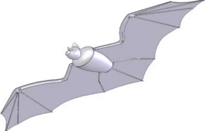
The basis for all construction and research methods is the BATMAV SolidWorks 3-D model of the bone structure. Former student Amanda Knutson first visited the North Carolina Museum of Natural Sciences with a set of calipers to take measurement of an actual bat skeleton and body. Lisa Gatens, head Curator of Mammals at the museum gave access to a recently dead bat that was frozen then thawed to allow measurements and interaction with all the workings of muscles, bones, and membrane. From the measurements taken of the bones of an average sized Silver-Haired bat Knutson constructed a three dimensional model in SolidWorks as an accurate representation of the skeleton laid flat at full extension as shown below.
5.2 Rapid Prototyping
The 3-D model can then be fed directly into a 3-D rapid prototyping printer using a multitude of materials ranging from epoxy to plastic to create the individual bones of the skeleton. In phase one, the first model was produced in the NCSU Rapid-Prototyping Lab via a
Stereolithography Apparatus (SLA). To create a cured epoxy part, the SLA makes many cross-sections about 0.005” thick of the three-dimensional model to create layer paths for a high-intensity laser to follow. A perforated metal plate is set inside a vat of photosensitive epoxy and lowered bit by bit as the laser traces and solidifies each cross-sectional slice of the part together. A short time later, the entire part is completed in this manner from the bottom up. An ABS Plastic 3-D printer was also used, which operates in a similar manner, creating thin layer upon layer, only it uses a modified inkjet printer head to lay lines of molten plastic. The results and characteristics of each process are diagramed in detail in sections 5.5 and 5.6.
5.3 Smart Materials
One of the motivating factors for choosing a bat was the applicability of smart materials, or more specifically, shape memory alloy (SMA). Nickel-Titanium (in a 50/50% alloy) wires are capable of superelastic as well as actuatoric motion. When heated, the wires contract up to 8% of their length, creating extremely efficient linear actuators, which can be controlled with an electrical current. Varying the current through the wires turns them into resistive heat elements, allowing precise control of the overall strain seen to make them ideal for a muscle system.
Smart materials present significant advantages over otherwise appropriate metals such as spring steel, which is flexible and durable, but cannot survive the same levels of strain without plastic deformation. Ordinary spring steel can undergo a strain of 0.2% along it’s length before exhibiting plastic deformation, whereas SMAs can reach up to 8.0%, as outlined earlier. Figure 1 compares the stress-strain curves of these two materials to show the effective ranges of operation.
Figure 2: Stress-Strain comparison of SMA to spring steel
To demonstrate the effectiveness of the SMA wires as joints we refer to simple
wires would never bend beyond 45 degrees in any one direction, meaning a maximum amplitude of 90 degrees rotation about the equilibrium. Here, we’ll test a 90 degree deflection to show what would happen if the bones were somehow forced to double their anticipated range of motion.
In a beam deflected only by a moment acting at its end we know that the angle of deflection, φ, is related to the ratio of the beam length, l, to the radius of curvature, ρ. Beam theory tells us that since the ends remain plane, the deformation at the inner and outer surfaces are proportional to the distance from the neutral axis.
l=1.4mm d=0.14mm
!="y# # = 1 $
From this relationship we derive the inner and outer maximum strains to be
!" !x =
#" #l
!y
$ =
!x l =%max
For a given angular deflection the beam creates an arc with a constant arc length and thus a particular radius of curvature. For φ = 90°, the radius is
!= l
" = 1.4mm
(
)
# 2 $ %& '()=0.8913mm
Thus,
!max =
"y # =
d 2 $ %& '()
# =
0.07mm
(
)
0.8913mm
(
)
=0.07854*0.08 or 8%
Figures 4-5: Simple single-wire joint between humerus and radius bones
In addition to resisting permanent deformation, the SMA wire would also operate with little risk of cyclic fatigue. If the joints wires were made of a steel alloy, even spring steel, they would see strains an order of magnitude higher than their elastic range. Each time the joint bends the wire would be deformed again, work hardening the material, making it brittle, until the wire eventually breaks. The SMA, however, would never plastically deform, and more than that, at strains in the range of about 1% the wire can actually achieve an infinite fatigue life. Even the joints that see much larger rotations will have fatigue life several orders of magnitude greater than spring steel [17].
5.4 Wing Membrane
The final step in creating the passive structure is determination of the wing membrane material and attachment method. The actual bat membrane consists of a finely wrinkled skin impregnated with a grid of flexible veins, as described in section 4.3. The operation of this membrane is catamount to creating lift and thrust while being durable and incredibly lightweight. Choosing and employing a material that meets or exceeds the elastic and
5.5 Initial Design
5.5.1 Skeleton
To begin the BATMAV project, former student Amanda Knutson visited the North Carolina Museum of Natural Sciences with a set of calipers to take measurement of an actual bat skeleton and body. Lisa Gatens, head Curator of Mammals at the museum gave us access to a recently dead bat that was frozen then thawed to allow measurements and interaction with al the workings of muscles, bones, and membrane. From the measurements taken of the bones of an average sized Silver-Haired bat Knutson constructed a three dimensional model in SolidWorks as an accurate representation of the skeleton laid flat at full extension as shown below.
At first the body was modeled in two parts with a separate head acting as an aesthetic place-holder before future revisions. The body, as shown below, consisted of two halves that joined together with a small plug such that the cargo carrying cavity could be accessed easily and filled with the necessary electronics. The bones had hollow ends for insertion of the SMA joint wires. The fingers and tail were modeled as single bones, and the wrists as solid blocks, primarily for simplicity sake in the first phase of development. At this point the base models were transferred to me to begin construction and design revisions.
Figure 6: SLA epoxy produced body and arm bones
It is worth noting here that the SLA machine at NCSU is old and has a larger laser beam width than current technology, and thus a lower resolution of around 0.050” laterally. Also, when finished, the pieces are not at full strength and must cured for a few hours in an
ultraviolet chamber. When they are removed from the vat of epoxy, a fair amount of viscous build-up occurs on the surface and in any orifices in the parts that must be cleaned
thoroughly prior to final curing to avoid solidifying the messy surface. This is a difficult undertaking by hand, and perhaps an ultrasonic bath would do a better job of finely cleansing the parts.
make the joining surfaces no longer square. All this leads to excessive amounts of
modification using a Dremel tool and X-acto knife just to get parts to fit together. One of the desirable traits of the SLA process was the expectation of being able to send out model files and have parts quickly produced and shipped without excessive human involvement in order to maintain consistent quality and resolution. When extra steps are added to clean parts or to further modify parts by hand there is no guarantee of consistent fitment and the results for this process fall short of expectations.
In order to place the joint wires in the bones holes had to be made, so several simple procedures were tested to create holes roughly half a millimeter in diameter. Drilling the bones quickly cracked the epoxy in chunk and made the ends too weak to hold together. Next a hot needle was stuck into the end to melt a hole in while concentrating heat to keep the entire material from deteriorating. This method worked better, but was still very inconsistent and did weaken the joint.
5.5.2 Membrane
Selecting an appropriate membrane material is crucial to replicating natural performance characteristics. Initially silicone rubber and gelatin resin were compared in small sheet samples to decide which was worth pursuing in this first phase of design. The silicone rubber had many enticing qualities, with high temperature resistance, consistent spring constant, and a range of casting approaches. However, it was much stiffer than the gelatin and sprang back instantly when stretched. Ultimately, the gelatin resin, commonly referred to as “Ballistics Gel,” became the choice for its very low melting and working temperature, making it easy to pour and cast sheets with low heat sources such a stove-top, and its natural feeling response. Gelatin resin commonly is formed by dissolving 1 part gelatin powder in 9 parts warm water according to mass, then chilling it 39°F. It is used principally for ballistics testing for its fairly accurate replication of flesh and natural tissue.
When cast in a thin sheet, the gelatin is very stretchy and retracts at a more natural rate, similar to memory foam. This feature seemed to more accurately emulate what was felt by stretching the real bat wing and allowing the veins and fibers to retract. Also, it was surprisingly resilient to puncture. Taking a 500-micron wire roughly cut with wire cutters and sticking it directly into the membrane caused the membrane to “tent” up significantly before finally breaking through the surface.
Figures 7-8: Puncturing membrane with 500-micron wire with negligible observed propagation
at a proportional rate. This trait is impressive and very applicable to this project to prevent small damage from resulting in catastrophic failure.
With the desirable traits come several difficulties. While the low melting temperature allows the gelatin to be worked and poured without industrial equipment, it also means that it burns very quickly. When put in contact with a source above 70°C the material immediately burns and hardens. Later on this may cause problems if put into contact with SMA actuator wires that can reach up to 100°C in normal operation. For now, it simply means that the material has a small window of working temperature and begins to gum up soon after it is melted.
The high viscosity of the melted gelatin also means great pressure is required to create very thin sheets. In an attempt to conserve simplicity and low-cost, small-scale production methods, the first mechanism used to make sheets consisted of two 5/8” thick aluminum plates with ridges machined to 0.25mm tall in strips around the edges and two C-clamps. As expected, the plates bottomed out on the ridges and with the help of the clamps, squeezed the excess gelatin out, resulting in a 0.25mm thick sheet when cooled, with little difficulty.
Figure 9: This membrane cast between milled aluminum plates
was used, too much pressure was needed to squeeze out the gelatin, and the sheet ended up too thick. Overall, the first membrane sheet cast demonstrated all the desirable
characteristics we were looking for, with only a few production issues.
5.5.3 Full Assembly
For compiling the first iterative design 32-gauge copper wire, used in wrapping electro-magnetic coils, was used as a place-holder for the SMA wire; this decision was made due to the low availability of thin SMA samples as well glaring inadequacies in the skeleton design itself needing change prior to full assembly. Since there was a large supply of 500-micron NiTi wire available, sections were used in place of the fingers, legs, and tail since their size was on the order of what was desired. The membrane cast of gelatin resin was
Figure 10: First iteration full assembly (“the headless wonder”)
This iteration was effective for comparing size and construction to an actual bat, but was intended to act as a pre-test with similar, yet inferior materials in most places, to compare scale and range of motion. As expected, the copper wire joints very quickly fatigued and snapped in each joint, but they served their purpose in the quick production of a full skeleton prior to membrane attachment and allowed testing of the range of motion of the limbs. The stiffness of the membrane material was keeping the humerus from extending forward enough to create the proper angle of downstroke. This problem means that the membrane must be relieved between the humerus, body, and upper leg somehow, by means of a fold or wrinkling or some other method.
5.6 Skeleton Final Design
5.6.1 Motivation for Materials
First and foremost, the issues resulting from the SLA epoxy production process need to be addressed. As discussed earlier, the body shell, latch, and bones all had significant fitment problems due to build-up of epoxy on the surface and in orifices during the initial laser curing. When cured fully in a UV chamber the excess epoxy hardens even when cleaned fairly thoroughly, creating the poor resolution component. A decision was made to test the design with a 3-D printing RP process using ABS plastic in addition to the epoxy. The results were encouraging.
In the aforementioned process molten plastic is printed through a 0.5mm printer head in layers, moving along in a very similar fashion to the SLA. Each successive layer bonds to the previous as the plastic cools and hardens, creating a cohesive unit. Since the only curing device is temperature and a relatively low temperature difference is seen, expansion and contraction is kept to a minimum, leading to much improved resolution and clean fitment.
Secondly, geometric changes had to be made to the first phase model to increase the strength of the bones and aid in construction. The radius and humerus were both changed to a
constant radius of 2.0mm with the hollow ends increased to 0.75mm in the hopes that they could be cleaned effectively prior to final curing to avoid drilling or skewering after the fact.
piece for extra storage capacity and simplicity, in addition to aesthetic purposes. The second skeleton weighed in at a scant 4.2 grams, a 50% reduction.
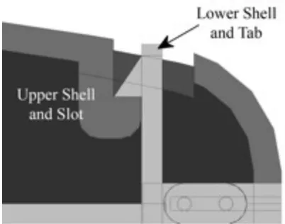
Figure 11: Body shell latch design, viewed from side
Figure 12: First phase body design (left) compared to improved second phase (right)
plastic produced via three-dimensional printing was the clear-cut winner and used for the final design.
Figure 13: ABS plastic via 3-D printing (left) versus SLA epoxy body (right)
5.6.2 Features and Construction
For the final phase of skeletal revision in this project more attention was paid to details of the actual flapping motions experienced during flight. The second iteration exhibited superb flexibility of all joints in all directions and that is actually somewhat undesirable. Bats have plate-like ends to their bones at the elbow and wrist and shoulder blades at the shoulder that create pseudo-pin-joints allowing motion principally in one plane. The natural rigidity of the joints also creates a static camber in the wing to aid in creating lift by modifying the leading and trailing edges. Having extraneous mobility forces the future muscle system to exert forces simply to maintain the shape necessary in gliding flight, which is not how nature has optimized the muscle system.
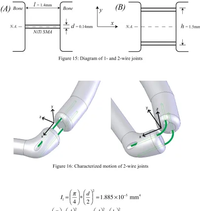
While the bones could be modified to contact one another with pinned joints, the scale and construction of those features would be extremely tedious to construct, require maintenance, and be weakened by the allowable thickness of the ABS plastic. A simpler, more elegant solution was employed to replace the single 140-micron SMA with two in plane.
Figure 15: Diagram of 1- and 2-wire joints
Figure 16: Characterized motion of 2-wire joints
I1= ! 4 " #
$ % & ' ( d 2 " # $ % & '
2
=1.885)10*5 mm4
I2=2( ! 4 " #
$ % & ' ( d 2 " # $ % & '
2
+2! ( d
2 " # $ % & '
2
( h 2 " # $ % & '
2
This addition would increase stiffness in the x-y plane by three orders of magnitude, while still allowing easy motion about the y-axis. The outer wires would act in tension and
compression, essentially extending the base of the moment of inertia in one direction, forcing a natural mode of flex in one plane. With this arrangement the joints remain very flexible and durable in the directions needed while reducing the steady-state demand on the muscle system without significant added cost of complexity in construction.
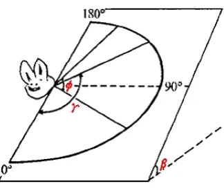
Hollow ends in the bones were widened in the plane perpendicular to the direction the natural bat joints flex and extra holes were added to make proper seating of the wires easier and stronger. For example, the shoulder actually moves at angle between 60 and 70° to the vertical during up and downstroke, thus the two joint wire holes were place at an angle in the body to force the correct motion.
Figure 17: Wing-stroke plane
Note that in Figure 17, φis the stroke angle of the wing(i.e. the total excursion angle of the wing); γis the positional angle of the wing, measuredin the stroke plane from the
The construction steps for skeleton and joints are outlined as follows (see Figure 18):
1. Clean sections SMA joint wires with acetone for surface prep 2. Clamp bones and wires into jig for setting
3. Insert wire into hole(s) in bone/body (except on finger bones) 4. Mix and apply adhesive around bone and wire thoroughly 5. Allow adhesive to cure before removal
6. Repeat for attachment to body and other bones
Previously, the joint wires were attached with simple super glue and were not particularly resilient. Examining the joint connections revealed that the extremely stiff epoxy or glue would not adhere to wire surface well and allowed the straight wire to delaminate and slide out of the hole in the adhesive. Researching stronger bonding agents led me to find J.B. Weld two-part steel epoxy. Unlike other two-part formulas, JB Weld uses one part steel-infused resin with a hardener. The end result is an adhesive that is not brittle and bonds much more effectively to a metal surface, like the NiTi wires.
Figure 18: Assembly of 2-wire joint with JB Weld steel epoxy
Overall, the assembly and curing processes are simplified, the surface of the joint is cleaner, and the adhesion is stronger than before.
In an effort to further decrease the chances of wire delamination and pull-out, two wires were consolidated into one that was bent into a sharp U-shape as shown above. On several joints the wire could be placed through the back of the holes or simply draped around the end of the bone before covering with JB Weld. The open ends of the wire were bent slightly at the end after setup, the idea being that when covered with JB Weld the bend would be encased in epoxy and create another physical barrier to overcome instead of a straight wire simply sliding out of a straight cavity. As a result, the end skeleton is much stronger and more durable than previous iterative designs while achieving a more defined or preferred plane of motion.
5.6.3 Comparative Results
Most evident from a cursory glance is the increased rigidity created by the two-wire joints. When the second iteration skeleton with 1-wire joints is lifted, the arms simply flop down and drag under their own weight. After handling a real bat, simple extension of the wings reveals the natural camber and rigidity of the bone joints as shown below. The new joints allow the skeleton to remain in plane under gravity, meaning the actuator wires will have to work less to stabilize the rest position, making the system more efficient and more like nature’s design.
Figures 20-21: Second iteration skeleton laying on flat surface (left) and dangling (right)
Figures 22-23: Third iteration skeleton laying on flat surface (left) and dangling (right)
the joint stronger, in turn making it more flexible and durable for ease of opening and closing the body cavity.
Figure 24: Body locking tab after acetone treatment (left) and without (right)
Figure 25: Body texture after acetone treatment (left) and without (right)
Figures 26-27: 2-wire joint (left) and full final assembly (right)
Figure 28: Fully assembled 6.3g BATMAV with membrane during attachment curing
Figure 30: Fully assembled BATMAV Skeleton
Table 1: Critical BATMAV Dimensions Component/Dimension Measurements (mm)
Wingspan 257
Body Length 59.5 Body Width 26.7 Body Depth 17 Radius Length 40.5 Radius Diameter 2.0 Humerus Length 27 Humerus Diameter 1.5 Upper Leg Length 20.75
Upper Leg Radii 1.25 x 0.625 Wrist 2.5 x 3.5 x 5.0
5.7 Membrane Material Study
5.7.1 Performance Goals
Before jumping into declaration of an ideal membrane material, proper performance parameters for a real bat membrane must be determined. Even at the most basic of levels without destructive testing on bats there is a lot to be realized that will greatly aid in the search for a creative and effective artificial membrane.
Initially the gelatin resin was chosen for, among other things, its natural feel. This feel could be described as a less linear elastic relation, where the equilibrium position was not achieved instantly upon release after being placed under tension. Rather, the material somewhat slowly returned to its original position in a much more regulated fashion instead of a quick, snapping motion like a spring. However, looking more closely at human and animal tissue reveals that neither of these are the reactions we are looking for.
opposite fashion where it is extremely easy to deform and stretch at first only to significantly stiffen at a certain point. This feature gives the membrane the feeling of increased strength under higher load [18].
Figures 31 and 32: Stress-strain curves for typical rubber and animal tissue [18]
The reason this is important lies in how the membrane and wing structure create lift. In between the bones the membrane parachutes, or takes on semi-circular shape to catch the air and create lift while minimizing drag. As wind load, or lift force, increases the idea is that the membrane only parachutes or extends that shallow semi-circular shape slightly since a stall curves membrane would not be aerodynamically efficient. The stress-strain curve for animal tissue allows the material to create an initial pocket under ambient air pressure, but at a certain point it simply stops expanding. The feel of this is somewhat like pulling on a very light spring with a longer piece of string attached to it. Once you stretch to the initial length of the string, an exponential increase in load is required to see relevant deflection. This function is a very efficient way to achieve lift in this application and should be the goal.
Examining a real bat further verifies the previous concept. When stretching the bat’s seer-sucker like wing membrane it stretches fairly easily until it reaches a point where it seems to simply not stretch anymore. This reaction is as much a function of the natural material properties as it is the composite structure as discussed earlier with bat physiology.
much closer to what we need and all future materials should go through simple force-deflection tests if stress-strain relations are not explicitly known.
Some of the most critical specifications required are basic geometry. A real bat membrane can very between 0.02 up to 0.15mm in smaller species and can be estimated to weigh less than half a gram. The vast majority of artificial materials produced at small thicknesses are done so through rolling procedures to achieve uniform thickness with great accuracy. It is likely an ideal material would have a similar production process and should be tested for such, but ultimately may not be necessary if it can be achieved consistently by some other method.
Always a concern with such thin materials is durability. Smaller bats can travel at speeds between 20 and 30mph at peak and see flapping frequencies on the order of 10Hz. If a material does not return to a zero-deformation state in the window of 0.05s then it is likely to not only fail during operation, but not achieve efficient performance en route. Furthermore, the blood vessels in the membrane create a fibrous network for the wing, meaning that if a small hole is made in a portion of the skin, it should not extend beyond any of the fibers bordering it under normal loading. The ideal material should also be strong enough to survive small punctures without significant propagation. Another nice feature of a living tissue is that it does not dry out or degrade because of the constant blood flow through it. Similarly, the ideal choice for an artificial replicate should be able to withstand the convective air flow of normal flight coupled with heat and humidity potentially seen in extreme outdoor environments. All of this must be achieved, while maintaining the lowest possible sprung mass.
5.7.2 Production and Attachment Methods
Since most engineering materials that are needed in very thin cross-sections or sheets are rolled, the membrane was tested with the same procedure. Given that is initially a very viscous material when hot, the main problem with this process comes in keeping the material from sticking to the roller. Non-stick sprays and flour were used with almost no effect, except to create bubbles and degrade the consistency of the material. The end result is a sticky, blobby pile of resin with zero usefulness. This does not by itself mean that the
material cannot be used, it simply means that it cannot be produced with a common, effective process for such applications.
Figure 33: Membrane attached using molten gelatin resin and injection needle
5.7.3 Testing Procedures and Results
Two of the criterion to be tested are the overall stress-strain characteristics and the durability over time. A simple pull-test can establish a reading for both by converting force-deflection data for a 100mm x 30mm sample strip into stress-strain and charting it over time. As the membrane sample sits in open air it begins to dehydrate, making it much stiffer than when originally cast.
For this specific test a calibrated spring force gauge was connected to a clamping block with the membrane attached to a fixed end on a scale. Pulls were made at various loads from 50 grams up to 500 at regular time intervals and recorded. Two different thicknesses were tested for verification and comparison, ~0.21mm and ~0.07mm.
Figure 34: Membrane Force-Deflection Testing Rig
Table 2: Hysteretic stretch behavior
The first sample was approximately 0.20 to 0.22mm thick, the second between 0.05 and 0.09mm (difficult to gauge precisely given elasticity of material). The data taken indicates that the thicker sample doubled in stiffness after about two and a half hours with an
approximately 220% increase after 24 hours, while the thinner one experienced a much sharper initial decline. This response coincides with the concept that the greater the surface area-to-volume ratio, the faster the material dries out, which will only be amplified further as the membrane thickness is decreased in an effort to optimize the system.
Table 3: Strain decay over time for single load
Also worth noting, when the 0.07mm sample was held at a constant load of 500g for 30 seconds on the 48-hour mark, the stretch length started at 160mm and continued slowly creeping out to 210mm. Given that the membrane was initially 115mm, this shows that the membrane can over double its expansion at a constant load over time when it is dry. However, it did not ever return to its original length, settling at just over 30% longer. In an application where lift is generated entirely by such a membrane, large expansions like this could lead to massive parachuting of the wings, diminishing response time and accuracy. Also, keep in mind that an appropriately sized membrane for the BATMAV could be on the order of 0.02 to 0.04mm.
more and eventually reach a point where it gives out and fails, or worse, where it does not fail and rather never returns to anything close to its original length. Plastic deformation is exactly what we want to avoid at all costs.
Table 4: Stress-strain curves over time
Table 5: Olive oil coated sample stress-strain curves over time
Given the somewhat backwards effect the olive oil had, coupled with the continuing
Table 6: Flour coated sample stress-strain curves over time
5.7.4 Conclusion and Recommendations
Using coatings like oil and flour mainly attempts to counteract some of the negative aspects of the gelatin resin; with other materials, surface treatments may not be necessary. Both treatments applied here aided in construction by reducing the stickiness of the surface, but degraded the moisture retention, effectively shortening the effective lifespan of the material. Explaining this reaction is difficult given that the motivation for olive oil was mainly to lock in the moisture by creating an impermeable layer on the surface. All tests were performed in open air in a room with a controlled temperature of 70° F and relative humidity between 35-45%.
6. RESULTS AND CONCLUSIONS
6.1 Process Approach
The BATMAV process began with an initial examination of a real bat’s physical make-up and dimensions. From there, a three-dimensional SolidWorks model was created for the skeletal structure to be sent directly to a 3-D printer that uses molten ABS plastic to create all the necessary components in a matter of minutes to a high level of resolution. Once
produced, the plastic bones can be joined using J.B. Weld adhesive, simple clamp jigs, and 140-micron superelastic NiTi shape memory alloy wires. The joint wires are epoxied to the ends of the bones to join together the full skeleton before attached a press-molded flat sheet of gelatin resin approximately 0.07mm thick to it. Hot resin is injected via a fine-tipped syringe over the bones and melds with the resin sheet to firmly attach the wing membrane to the skeleton. In this way, BATMAV was initially created and can be continually updated to fine-tune performance during the later stages of development.
6.2 SolidWorks Bone Structure
After assembling the third iterative design, several key features and materials can be detailed for future research. The primary material choice for the skeleton is ABS plastic in a three-dimensional printer. The body has a simple snap-hook design to hold on the upper shell, which is strong enough to put adequate pressure on the membrane along the edge as an extra level of hold beyond the gelatin adhesive used to attach it to the lower half. The thickness of the shell is optimized for accurate printing while meeting strength requirements of assembly and creating the largest cavity possible for future application of electronics. At the ends of the bones are small holes positioned for placement of the joint wires to facilitate motion in a specific plane. Changing the angle of this plane for more exact tuning of the wing motion is a quick modification to make in the SolidWorks model. Similarly, any bone or body
dimension can be changed with relative ease and produced quickly with RP to allow several iterations of geometric tuning of the skeleton for performance.
6.3 Rapid Prototyping
The ABS plastic is an improvement over the SLA epoxy. Three-dimensional printing techniques are accurate enough even in older machines to produce larger bones and the body to consistent tolerances either in-house or by another facility without the need for extensive post-printing cleaning or preparation. Dimensionally, the skeleton is small and extremely light, meaning each skeleton’s 4.2 gram weight can be made for less than $3 and with
turnaround time in just a few hours. As a result of the production process, modifications can be made to the design, printed in-house, and ready to assemble in the same day with ease, making tuning of the specific geometry and motion limitation a much faster process.
by the RP, including fingers, lower legs, and tail, are effectively replicated with 500-micron superelastic SMA wire. Under compression they exhibit comparable buckling strength at a similar diameter while having the added durability of a superelastic material that is not brittle.
6.4 Skeleton Assembly
Joining the bones are 140-micron SMA wires with two to three wires per joint attached with a quick-setting two-part steel epoxy. The J.B. Weld adhesive sticks to the small wire surface much more effectively than two-part epoxy and is easier to form into cleaner, better looking joints that require no attention after curing except from an aesthetic viewpoint, if desired. Assembling each joint can be done in less than 5 minutes including cure time with the use of a small clamp jig.
6.5 Membrane
Gelatin resin exhibits several natural elastic characteristics, as demonstrated by its most common application as ballistics gel simulating human flesh and tissue. Originally, the “ballistics gel” was chosen for its low melting temperature, ease of assembly, and natural feel. Further investigation leads to a membrane that is fairly functional, but in need of improvement.
Production of the membrane is a relatively simple procedure and only requires a 55~60°C heat source with no specialized machinery or automation to make a thin sheet. If needed, it can be constructed on a stove or with a propane torch and a glass beaker. This is a very positive feature in that it is easy to repair holes in membranes with low heat instead of complete replacement. However, to achieve the thickness needed to emulate a real bat’s dimensions and weight, more sophisticated tooling and processes are needed. This is certainly feasible, but was not considered for this particular stage of development given the scale and cost concerns.
Compared to a bat’s natural skin membrane, the gelatin is significantly thicker and slightly heavier, but it maintains elastic qualities within a currently acceptable and similar range. While the thin gelatin does dehydrate quickly, it can be stored in a sealed environment even as simple as plastic wrap to keep it fresh for weeks when not in use. Once the membrane does pass beyond its half-life, it is still light enough to function if attached initially at near full extension. In addition, it can easily be removed from the skeleton by hand with a small craft knife and replaced with a fresh membrane without damage to the bone structure.
However, if the gelatin degrades so much in stagnant, humid air, then faster decay can be expected in the harsher environments BATMAV will ultimately see action. Even if the membrane performs well initially, with the convective flow across it from normal flight the aging process could speed up significantly, resulting in changing physical nature and
not ideal, especially if the membranes have to be replaced after just one or two uses.
Furthermore, that would entail a tedious process that is neither time- nor cost-efficient in the field, especially with a large number of units in use.
Assuming the idea is to emulate real bat physiology as accurately as possible for the passive structure, then the stress-strain curves tell us that gelatin resin does not react as desired. Ideally, the material should get stronger and stiffer under higher loads, indicated by the sharp upswing in the stress-strain relation. With an essentially linear response the gelatin resin is already at a disadvantage under larger wind gusts and higher thrust situations. While it is possible this response could be made to work, it is not the goal of this study. The bottom line is that gelatin resin can work as a membrane, but it is far from ideal for this application.
6.6 Overall structure performance
7. DISCUSSION OF RELEVANCE
These first few stages of development of the BATMAV have laid a critical foundation for the advancement of micro-aerial vehicle technology. The passive structure creates the
framework for application of artificial muscle systems using SMA wires as linear actuators. Research of mammalian flapping flight can now be applied to a new regime of small flyers with emphasis on natural designs straying from conventional fixed-wing aircraft.
To this point, the state-of-the-art in MAV technology has developed small craft with semi-rigid fixed wings that can fly distances over several kilometers and take high-resolution pictures with small payloads. To this point, they almost exclusively bring with them extremely loud propellers, poor stability in high winds, and the lack of maneuverability in tight spaces. With completely independent, non-rigid wings there is no propeller or engine noise and no need for long open areas for takeoff and landings. Furthermore, a flapping flyer can glide and hover, turn completely around in under a foot, and adjust to swirling winds by controlling the pitch and yaw of each wing separately. The basis for such a micro-aerial vehicle begins the passive mechanical structure developed here.
Furthermore, the technology employed in the entirety of the BATMAV forges forward in using SMA wires as actuators in small and large-scale designs to increase efficiency of operation. When a linear actuator driven by an electrical motor or a worm gear can be replaced with a single wire and a power source there is a significant decrease in size, weight, and complexity, while increasing the electromechanical efficiency of the system.
8. RECOMMENDATIONS FOR FUTURE RESEARCH
The likely place to begin in the next stage of development is a material study. This research has ironed out a solid structure of bones and joints and has presented the motivation for much more expansive material research for the membrane. The desired performance characteristics and guidelines for the membrane have been laid out here in detail and the next step is to follow the model set forth by the gelatin resin study to flush out a more ideal membrane. Gelatin resin has many desirable characteristics for application as a membrane, but it also is difficult to handle in certain stages and ages rather quickly. Ideal materials would be similar to the gelatin, with significantly improved longevity, workability, and consistency. Possible alliances with textile researchers could be advantageous in sourcing or developing a semi-elastic, composite fiber-based material that is more sophisticated and tuned for exacting specifications.
Along with the material choice comes the attachment method. If gelatin resin use is found to be ideal then the hot injection of the resin over the bone structure will be the choice.
However, other materials will likely not have the same physical characteristics that allow such forming methods and another way must be addressed early on.
After polishing of membrane details, the SMA actuator wires must be routed along the skeletal structure. First, the complex muscle system of the bat must be simplified and muscle placement determined to eliminate redundant actions or produce multiple contractive
Once the wires are attached and the membrane is firmly defined, shielding of the wires may be necessary. In the case of gelatin resin it will need to be determined if the wires become too hot during contraction and burn the membrane. In any case, the convective airflow across the BATMAV will undoubtedly affect response time of the wires since they react to temperature change. Thermal shielding may help lighten the load on the power source, but slow cool down, so some research must be done in this light.
![Figure 5: The University of Florida's semi-rigid wing MAV [12]](https://thumb-us.123doks.com/thumbv2/123dok_us/1240274.1156628/21.612.140.490.69.332/figure-university-florida-s-semi-rigid-wing-mav.webp)

![Figure 11: Plan-view of the ventral surface of the wing for a Plecotus auritus [15].](https://thumb-us.123doks.com/thumbv2/123dok_us/1240274.1156628/26.612.137.490.77.355/figure-plan-view-ventral-surface-wing-plecotus-auritus.webp)

![Figure 3: Euler-Bernoulli beam analysis of SMA joint wires [17]](https://thumb-us.123doks.com/thumbv2/123dok_us/1240274.1156628/31.612.99.518.185.592/figure-euler-bernoulli-beam-analysis-sma-joint-wires.webp)