ABSTRACT
LIN, ZHEN. Architectural Support for Efficient GPU Multiprogramming. (Under the direction of Dr. Huiyang Zhou).
Graphics processing units (GPUs) have become the most prevalent accelerator in high-performance
computing. Since more and more applications are leveraging GPUs to accelerate their performance,
the concurrent applications can potentially share the same GPUs. Therefore, there is an increasing
demand to enable efficient GPU multiprogramming. In this paper, we study the GPU
multiprogram-ming from two main aspects. First, we study efficient context switching techniques to enable kernel
preemption on GPUs. Second, we study how to co-run multiple kernels on the same GPU so that
the GPU resources can be optimally utilized. Specifically, this paper includes the following contents.
First, this paper presents an efficient support to enable fast context switching on GPUs.
Con-text switching is a key technique enabling preemption and time-multiplexing for CPUs. However,
for GPUs, it is challenging to support context switching due to the huge amount of architectural
states to be swapped during context switching. The architectural state of GPUs includes registers,
shared memory, single-instruction multiple-thread stacks and barrier states. Recent works present
thread-block-level preemption on GPUs to avoid context switching overhead. However, because the
execution time of a thread block (TB) is highly dependent on the kernel program. The response time
of preemption cannot be guaranteed and some TB-level preemption techniques cannot be applied
to all kernel functions. In this paper, we propose three complementary ways to reduce and compress
the architectural states to achieve lightweight context switching on GPUs. Experiments show that
our approaches can reduce the register context size by 91.5% on average. Based on lightweight
context switching, we enable fast instruction-level preemption on GPUs with compiler and hardware
co-design. With our proposed schemes, the preemption latency is reduced by 59.7% on average
compared to the naive approach.
Second, we leverage the lightweight context switching approach to improve the performance of
computation throughput and hide long memory latency. In our work, we characterize the kernels
that are limited by their TLP levels. To improve TLP for such applications efficiently, we propose to
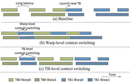
use a fast context switching approach. When a warp/TB is stalled by a long latency operation, the context of the warp/TB is spilled to spare on-chip resource so that a new warp/TB can be launched. The switched-out warp/TB is switched back when another warp/TB is completed or switched out. With this fine-grain fast context switching, higher TLP can be supported without increasing the
sizes of critical resources like the register file. Our experiment shows that the performance can be
improved by up to 47% and a geometric mean of 22% for a set of applications.
Third, in the scenario of multiple kernels co-running on the same GPU, we propose to
coordi-nately partition the TB and bandwidth resources for concurrent kernel execution (CKE).
Contempo-rary GPUs support multiple kernels to run concurrently on the same streaming multiprocessors
(SMs). Recent studies have demonstrated that CKE improves both resource utilization and
com-putational throughput. Most of the prior works focus on partitioning the GPU resources at the
TB level or the warp scheduler level to improve CKE. However, significant performance slowdown
and unfairness are observed when latency-sensitive kernels co-run with bandwidth-intensive ones.
The reason is that bandwidth over-subscription from bandwidth-intensive kernels leads to much
aggravated memory access latency, which is highly detrimental to latency-sensitive kernels. In our
work, we observe that such problems cannot be sufficiently solved by managing TB combinations
alone. Then, we propose a coordinated approach for TB combination and bandwidth partitioning.
Our approach partitions both bandwidth resources coordinately along with selecting proper TB
combinations. The key objective is to allocate more TB resources for latency-sensitive kernels and
more bandwidth resources to bandwidth-intensive kernels. Compared with two state-of-the-art
CKE optimization schemes, SMK[Wan16]and[Xu16], our approach improves the average harmonic speedup by 78% and 39%, respectively. Even compared to the best possible CTA combinations,
which are obtained from an exhaustive search among all possible CTA combinations, our approach
© Copyright 2019 by Zhen Lin
Architectural Support for Efficient GPU Multiprogramming
by Zhen Lin
A dissertation submitted to the Graduate Faculty of North Carolina State University
in partial fulfillment of the requirements for the Degree of
Doctor of Philosophy
Computer Engineering
Raleigh, North Carolina
2019
APPROVED BY:
Dr. Gregory Byrd Dr. Xipeng Shen
Dr. James Tuck Dr. Huiyang Zhou
DEDICATION
BIOGRAPHY
The author was born in Shijiazhuang, a northern city in China. He received his bachelor degree
of Electronic Engineering from Yanshan University in 2010, and his master degree of Computer
Science from Beihang University in 2014. He started his Ph.D. program in North Carolina State
University in 2014. Since then, he has worked on several research projects under the supervision
of Prof. Huiyang Zhou. His research mainly focused on GPU architecture and low-level software
design. He had internships as a GPU software engineer at Apple Inc. and GPU architecture engineer
ACKNOWLEDGEMENTS
First of all, I would like to express my deepest gratitude to my advisor, Dr. Huiyang Zhou. Dr. Zhou
has been a great advisor through my Ph.D. career. I am thankful for his encouragement, guidance,
as well as his critical challenges. Because without them, this dissertation would not even be possible.
Also, I would like to thank Dr. Huiyang Zhou, Dr. Gregory Byrd, Dr. Xipeng Shen, and Dr. James Tuck
for serving on my dissertation committee. Thank Dr. Yan Solihin for his insightful discussions.
I would also like to thank the colleague students in our CAS group, Chao Li, Hongwen Dai,
Hussein Elnawawy, Utkarsh Mathur, Mohammad Alshboul, Xiangyang Guo, and Qi Jia for their
contribution and advice in my research. Also, many thanks to Michael Mantor from AMD, Lars
Nyland and Jin Wang from NVIDIA for their valuable comments.
I am especially thankful for my wife, Wenshuang Hao, for her love and company during my
studying. I would like to thank my mother, Hong Lyu and my father, Xihai Lin, for their love and
TABLE OF CONTENTS
LIST OF TABLES . . . .viii
LIST OF FIGURES. . . ix
Chapter 1 INTRODUCTION . . . 1
Chapter 2 Enabling Efficient Preemption for GPUs with Lightweight Context Switching . 4 2.1 Introduction . . . 4
2.2 Background and Motivation . . . 7
2.2.1 Baseline Architecture . . . 7
2.2.2 Prior Preemption Techniques for GPUs . . . 8
2.3 Efficient Context Switching . . . 9
2.3.1 In-Place Context Switching . . . 10
2.3.2 Architectural State Reduction . . . 12
2.3.3 Architectural State Compression . . . 14
2.4 Context Switching for Preemption . . . 19
2.4.1 Selective Preemption . . . 19
2.4.2 Context Format . . . 20
2.4.3 Preemption Pipeline . . . 21
2.5 Experiments . . . 22
2.5.1 Methodology . . . 22
2.5.2 Spilling Latency . . . 24
2.5.3 Preemption Latency . . . 25
2.5.4 Worst Case Preemption Latency . . . 26
2.5.5 Impact of In-Place Context Switching . . . 27
2.6 Related Work . . . 27
2.7 Conclusions . . . 29
Chapter 3 GPU Performance vs. Thread-Level Parallelism: Scalability Analysis and A Novel Way to Improve TLP . . . 30
3.1 Introduction . . . 30
3.2 Background . . . 33
3.2.1 GPU Architecture . . . 33
3.2.2 Crossbar Interconnect Network . . . 34
3.3 Methodology . . . 35
3.3.1 Simulation Infrastructure . . . 35
3.3.2 Benchmarks . . . 36
3.4 Dynamic Resource Utilization . . . 37
3.4.1 Experiment Description . . . 37
3.4.2 Overall Results . . . 38
3.4.3 Scalability Analysis . . . 40
3.5.1 Which Benchmarks Benefit From Increased TLP . . . 41
3.5.2 Virtual Thread . . . 42
3.6 Improving TLP with Fast Context Switching . . . 43
3.6.1 General Idea . . . 43
3.6.2 Latency Hiding with Two-Level Context Switching . . . 44
3.6.3 Deadlock Avoidance . . . 45
3.6.4 Determining the Number of Extra TBs . . . 46
3.6.5 Warp States . . . 48
3.6.6 GPUDuet Architecture . . . 49
3.6.7 Context Switching Latency . . . 52
3.6.8 Hardware Overhead Comparing to Virtual Thread . . . 53
3.7 Evaluation . . . 53
3.7.1 Impact of Maximum Extra TBs . . . 53
3.7.2 Comparing with Virtual Thread . . . 55
3.7.3 TLP Improvement . . . 56
3.7.4 Impact of Context Switching Latency . . . 57
3.8 Related Works . . . 57
3.9 Conclusions . . . 59
Chapter 4 Coordinated CTA Combination and Bandwidth Partitioning for GPU Concur-rent Kernel Execution. . . 60
4.1 Introduction . . . 60
4.2 Background on GPU Architecture . . . 64
4.3 Methodology . . . 64
4.3.1 Simulation Specifications . . . 64
4.3.2 Benchmark Categorization . . . 65
4.3.3 Evaluation Metrics . . . 67
4.4 Limitations of CTA Management . . . 68
4.4.1 Effects of Bursty Memory Requests . . . 68
4.4.2 Prioritization of Memory Requests . . . 71
4.4.3 Coarse Granularity of TLP Control . . . 72
4.4.4 Motivation of Our Approach . . . 72
4.5 Coordinated CTA Combination and Bandwidth Partitioning . . . 72
4.5.1 Overview . . . 72
4.5.2 CCBP Algorithm . . . 74
4.5.3 Bandwidth Management . . . 77
4.5.4 CCBP-Parameter Detection . . . 80
4.5.5 CCBP with Adjustable Priorities . . . 82
4.6 Architectural Support . . . 83
4.6.1 Virtual Queues . . . 84
4.6.2 Request Arbitrator . . . 84
4.6.3 Tracking and Monitoring DRAM Accesses for df factors . . . 85
4.6.4 Overall Hardware Cost . . . 85
4.7.1 2-Kernel Co-Runs . . . 86
4.7.2 Impact on LS+BI Co-Runs . . . 88
4.7.3 Impact on NBI+DBI Co-Runs . . . 89
4.7.4 3- and 4-Kernel Co-Runs . . . 90
4.7.5 Comparison with Hybrid Approaches . . . 91
4.7.6 Sensitivity Studies . . . 92
4.8 Related Work . . . 93
4.9 Conclusions . . . 96
Chapter 5 Conclusion and Future Works. . . 97
LIST OF TABLES
Table 2.1 Baseline architecture configuration . . . 22
Table 2.2 Benchmark specification . . . 23
Table 3.1 Baseline architecture configuration . . . 35
Table 3.2 Benchmark specification . . . 36
Table 3.3 Throughput utilization classification . . . 47
Table 3.4 Storage overhead per SM . . . 49
Table 4.1 Baseline architecture configuration . . . 65
Table 4.2 Benchmark specification . . . 65
LIST OF FIGURES
Figure 2.1 Baseline GPU architecture. . . 7
Figure 2.2 Kernel code of persistent threads. . . 8
Figure 2.3 Occupancy of the register file and shared memory. . . 10
Figure 2.4 Register and shared memory allocation tables before and after K1 is pre-empted by K2. (a) Before. (b) After. . . 11
Figure 2.5 Possible thread locations when a preemption point is reached. . . 12
Figure 2.6 Normalized register context sizes after liveness analysis and compression. . . 13
Figure 2.7 A kernel code snippet of BP_1. . . 14
Figure 2.8 Warp-Level register value locality analysis. . . 14
Figure 2.9 TB-Level register value locality analysis. . . 16
Figure 2.10 Warp-level register state compression logic. . . 18
Figure 2.11 TB-level register state compression logic. . . 18
Figure 2.12 Kernel context format. . . 20
Figure 2.13 Saving and restoring pipelines for preemption. . . 21
Figure 2.14 Normalized spilling latency. . . 24
Figure 2.15 Normalized preemption latency. . . 24
Figure 2.16 Normalized worst case preemption latency . . . 26
Figure 2.17 Normalized preemption latency with in-place context switching . . . 27
Figure 3.1 Instruction per cycle (IPC), L1 D-cache hit rate and DRAM bandwidth utiliza-tion with different numbers of active warps for the SPMV benchmark. . . 31
Figure 3.2 GPU architecture. . . 33
Figure 3.3 A crossbar with queueing on inputs, assuming that the input number equals with the output number[Kar87]. . . 34
Figure 3.4 Benchmark categorization based on throughput utilization of GPU resources. 37 Figure 3.5 The impact of varied numbers of active warps for different interconnect bandwidth on SPMV. The left Y-axis is the throughput of L1 D-cache and interconnect (icnt). The right Y-axis is the IPC. The X-axis is the number of active warps. . . 40
Figure 3.6 Speedup for doubling the context resources per SM. . . 41
Figure 3.7 Occupancy of GPU context resources. . . 43
Figure 3.8 Context switching to overlap long-latency stalls. . . 44
Figure 3.9 Warp state transition diagram. . . 48
Figure 3.10 Block diagram of the GPUDuet architecture. . . 49
Figure 3.11 Warp and TB context table entry. . . 49
Figure 3.12 Normalized speedups of GPUDuet with varied numbers of maximum extra TBs (ME). . . 54
Figure 3.13 Performance comparison of GPUDUet with Virtual Thread (VT) and TB-level GPUDuet. . . 55
Figure 3.15 Impact of context switching latency. . . 57
Figure 4.1 GPU architecture. . . 64
Figure 4.2 Performance and latency impact for BP+CFD co-run using different CTA combinations. . . 69
Figure 4.3 The instantaneous NoC bandwidth demand of BP+CFD co-runs with different CTA combinations. . . 70
Figure 4.4 Instantaneous DRAM bandwidth utilization for CFD+FTD co-run and FTD standalone execution. . . 71
Figure 4.5 A snapshot of the L1 D-cache miss queue when a latency-sensitive kernel (kernel_1) co-runs with a bandwidth-intensive one (kernel_2). . . 71
Figure 4.6 An overview of the CCBP architecture. . . 73
Figure 4.7 4 memory transaction types, black dots represent the bandwidth is consumed at a particular component. . . 78
Figure 4.8 Architecture of an issue rate controller (IRC). . . 83
Figure 4.9 Overall performance of 2-kernel co-runs. . . 86
Figure 4.10 Harmonic speedup of 2-kernel co-runs. . . 86
Figure 4.11 Case studies of BP+CFD. . . 88
Figure 4.12 Bandwidth utilization of CFD+FTD. . . 89
Figure 4.13 Performance of 3- and 4-kernel co-runs. . . 90
Figure 4.14 Comparison with hybrid approaches. . . 92
Figure 4.15 Normalized harmonic speedups for varied queue sizes. . . 92
CHAPTER
1
INTRODUCTION
Nowadays, graphics processing units (GPUs) have become the most prevalent accelerator in high
performance computing. GPUs have been widely used in various application fields, such as machine
learning, computer vision, computational fluid dynamics, medical imaging, etc. Recently, companies
such as IBM, Google, Amazon and NVIDIA are providing GPU clouds so that applications from
different users/applications may potentially share one physical GPU card. Therefore, we see a strong demand for multiprogramming supports on GPUs.
The workload that is offloaded to a GPU is referred to as a kernel. Programmers use the CUDA
[Cuda]or OpenCL[Ope]programming models to define the behavior of each thread in a kernel. A
number of threads constitute a thread block (TB) and threads in a TB can communicate through
the on-chip shared memory. There are two perspectives to support multiple kernels sharing one
physical GPU. One is to enable preemption so that different GPU kernel can share the GPU in a
allow multiple kernels running on the same GPU simultaneously. This dissertation presents our
works on supporting the GPU multiprogramming from both perspectives.
In the first work, we propose a lightweight context switching approach to enable efficient
preemption on GPUs. Similar to the CPUs, context switching requires the GPU to save all the
architectural states of the running kernel to the memory so that the GPU can be take over by another
kernel. The states will be restored to the GPU when the first kernel is scheduled to continue running.
The challenge of supporting context switching on GPUs is that GPUs feature high amount of on-chip
resources to accommodate a large amount of concurrent threads. For example, in the NVIDIA GK110
(Kepler) architecture, each stream multiprocessor (SM) has a 256KB register file and up to 48KB
shared memory. Such large contexts result in long latency for context switching.
In our work, we propose novel ways to reduce and compress GPU contexts to enable lightweight
context switching. Three approaches are proposed. First, based on the observation that for some
applications, the on-chip resource is significantly underutilized, we propose in-place context
switch-ing, which means that not all resources need to be released/spilled to accommodate a new kernel. Second, liveness analysis is used to exclude dead registers so as to reduce the register context sizes.
In this work, we observe the liveness of a vector register is dependent on the thread divergence. So
the traditional liveness analysis algorithm is augmented for the GPU architecture. Third, based on
register pattern analysis, register contexts can be further compressed. These techniques can greatly
reduce the context size that needs to be swapped to/from off-chip memory.
Based on the lightweight context switching support,in our second work, we leverage the context
switching to improve the performance of a single kernel. To achieve high computation throughput
and memory bandwidth, GPUs exploit high degrees of thread-level parallelism (TLP). The GPU
hardware aggregates multiple threads into a warp as the basic execution unit. The warp scheduler
seeks for one ready instruction among multiple warps every cycle. Such fine-grain multithreading
is the key to hide memory latency. As a result, GPUs feature high amounts of on-chip resources to
accommodate the contexts of large numbers of concurrent warps.
regis-ter file capacity or warp scheduler capacity, of the GPU. We also noticed that, for many benchmarks,
resource usage is unbalanced. Often, shared memory is underutilized and/or the L1 D-cache perfor-mance is low. For these benchmarks, shared memory or the L1 D-cache can be used to accommodate
more warp contexts. In this work, we propose a novel approach using context switching as another
level of multithreading for GPU architecture. The key idea is to switch out stalled warps/TBs to realize much higher degrees of TLP without increasing the size of critical physical resources. In order
to achieve fast context switching, we only use on-chip memory to store the switched out contexts.
Our experiment shows that the performance of single kernels can be significantly improved by our
approach.
In the third work, we study the case of concurrent kernel execution (CKE), i.e. multiple kernels
co-running on the same GPU. To deliver high throughput, GPUs incorporate a large amount of
computational resources and support high memory bandwidth. However, the resource demands
across different GPU kernels vary significantly, which may lead to saturation of certain resources
and underutilization in others. Some prior works[Wan16; Xu16; Par17]have been proposed to solve the unbalanced resource utilization problem through concurrently executing multiple kernels with
complementary characteristics. In their approaches, different methods are proposed to determine
the TB combinations of different co-running kernels.
In our work, we highlight that memory interference can significantly affect the throughput and
fairness of CKE. And we make a case that even the optimal TB combination does not eliminate the
negative memory interference impact. To address this problem effectively, we propose a coordinated
approach for TB combination and bandwidth partitioning. In our approach, we first dynamically
detect the kernels as latency sensitive or bandwidth intensive. Then it effectively allocates the TB
number and bandwidth resources for each co-running kernel based on their resource requirements.
In our experiments, we observe that our approach achieves higher performance than the
state-of-the-art CKE approaches and the oracle TB combination, which is the result of an exhaustive search
CHAPTER
2
ENABLING EFFICIENT PREEMPTION
FOR GPUS WITH LIGHTWEIGHT
CONTEXT SWITCHING
2.1
Introduction
State-of-the-art GPUs exploit high degrees of thread-level parallelism (TLP). As a side effect, GPUs
feature high amounts of on-chip resources to accommodate the contexts of the large numbers of
concurrent threads. For example, in the NVIDIA GK110 (Kepler) architecture, each stream
multipro-cessor (SM) has a 256KB register file and up to 48KB shared memory. Such large contexts result in
the running threads/warps, which GPUs support natively). To reduce the overhead, TB-level context switching techniques, SM-draining[Tan14]and SM-flushing[Par15a]have been proposed. The key idea of SM-draining is to wait for all running TBs on an SM to finish, then to launch the TBs from
the new incoming kernel to the SM. The drawback of this solution is that the preemption latency
can be very high. In the worst scenario, a TB can have a lifetime as long as the kernel[Gup12] [KB14], and the kernel may not be preempted at all. SM-flushing flushes the running TBs and then launches
the new kernel. The limitation is that only kernels which conform the idempotent (re-executable)
condition[KS11]can be preempted in this way. Also, the useful work is wasted when a running TB is flushed. To overcome such limitations, an integrated solution[Par15a]is proposed based on the progress of a TB. If it is close to the end, TB draining is used. If it just begins execution, TB flushing
is employed instead. In other scenarios, the baseline context switching, i.e., swapping the thread
contexts, is performed.
In this paper, we propose novel ways to reduce and compress GPU contexts to enable lightweight
context switching. Three approaches are proposed. First, based on the observation that for some
applications, the on-chip resource is significantly underutilized, we propose in-place context
switch-ing, which means that not all resources need to be released/spilled to accommodate a new kernel. Second, liveness analysis is used to exclude dead registers so as to reduce the register context sizes.
In this paper, we observe the liveness of a vector register is dependent on the thread divergence.
So the traditional liveness analysis algorithm is augmented for the SIMT architecture. Third, based
on register pattern analysis, register contexts can be further compressed. The register pattern is
explored in both warp-level and TB-level. These techniques can greatly reduce the context size that
needs to be swapped to/from off-chip memory.
Based on the lightweight context switching, we use compiler and hardware co-design to enable
instruction-level preemption for GPUs. The compiler analyzes the native assembly code to figure out
the appropriate points for preemption. We introduce two new preemption instructions to annotate
the preemption points, meaning that preemption is only enabled at this point. The preemption
is an interrupt signal, the context switching is handled by a special hardware pipeline to reduce
and compress the architectural states. At last, the compressed states are saved to global memory.
To restore the kernel, the context will be loaded from global memory. After decompressing, the
architectural states are restored on the processor.
Besides preemption, our proposed lightweight context switching can also be used for long
running applications on supercomputers. The reason is that long running applications on
super-computers are error prone. Therefore, checkpointing mechanisms are commonly used such that the
supercomputer can resume from a prior checkpoint in the case of an error. Our proposed scheme
enables efficient context saving, i.e., efficient checkpointing of GPU contexts.
We evaluate our context switching enabled preemption approach with the Rodinia[Che09a] benchmarks. Our experiments show that the register context size can be reduced by 91.5% and the
preemption latency can be reduced by 59.7% on average with our proposed lightweight context
switching.
In summary, this paper makes the following contributions.
• We propose three techniques, in-place context switching, register liveness analysis, and
regis-ter value compression to achieve lightweight context switching.
• A compiler and hardware co-design is proposed to enable instruction-level preemption for
GPUs.
• We show that our proposed approach achieves low preemption latency.
The rest of the paper is organized as follows. Section 3.2 describes the SIMT architecture and
motivates the proposed ideas. Section 2.3 presents the techniques for lightweight context switching.
Section 2.4 makes use of lightweight context switching for efficient instructional-level preemption.
Section 2.5 reports the methodology and experiment results. Section 2.6 discusses the related work
Interconnect
Global Memory
... ...
Shared
Memory Registers
L1 Cache SIMT Stack
...
Shared
Memory Registers
L1 Cache SIMT Stack
L2 Cache
Global Memory L2 Cache ...
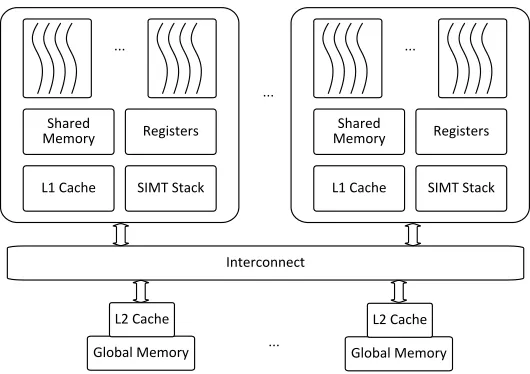
Figure 2.1Baseline GPU architecture.
2.2
Background and Motivation
2.2.1 Baseline Architecture
Figure 2.1 shows the baseline GPU or GPU architecture. A GPU is composed of a number of streaming
multiprocessors (SMs). The SMs share a multi-banked L2 cache. Typically, one or more L2 banks are
backed up with a memory controller to communicate with off-chip memory. The SMs and multiple
L2 banks communicate through a crossbar or an interconnect network. The on-chip memory in
each SM includes shared memory, the register file and L1 D-cache. The basic execution unit in GPUs
is a warp. A warp is a collection of threads that run in the single-instruction multiple-data (SIMD)
style. Each warp has a private space in the register file. A per-warp SIMT stack keeps track of the
program counters (PCs) of the threads when a divergent branch is encountered[Fun09]. One or more warps constitute a thread block (TB). All threads in one TB can synchronize and share data
through shared memory. The threads in the same TB must be executed on the same SM and one SM
can accommodate one or more TBs depending on the resource requirement of a TB.
When a kernel is launched, the resource requirement of a TB is provided to the GPU. Based on
void k e r n e l ( f l o a t A , f l o a t B ,
i n t Ahead , i n t Bhead , i n t N) { i n t i n _ i d , o u t _ i d ;
while ( ( i n _ i d = atomic_inc ( Ahead ) ) < N) { f l o a t i n _ d a t a = A[i n _ i d];
f l o a t out_data = do_work ( i n _ d a t a ) ; out_index = atomic_inc ( Bhead ) B[out_index] = out_data ; } }
Figure 2.2Kernel code of persistent threads.
types of resources that can limit the number of concurrent TBs on an SM: the register file, shared
memory, the warp scheduler, and the TB slots. For example, in the NVIDIA GT200 architecture, the
register file size is 128KB, the shared memory size is 48KB, and there are 48 warp scheduler slots
(i.e., up to 48 warps can run concurrently) and 8 TB slots on each SM. For a kernel with 8 warps
(i.e., 256 threads) in each TB, if each warp takes 3KB register space and each TB takes 8KB shared
memory space, the maximum TB per SM is 5 as limited by the register file size. A warp/TB will hold the resources during its whole lifetime. The resources will be released only after it finishes execution.
2.2.2 Prior Preemption Techniques for GPUs
The large context size on GPUs leads to high preemption overhead. To avoid the overhead, Tanasic
et al.[Tan14]proposed the SM-draining technique, in which all current running TBs need to finish before releasing the SM for the new kernel. However, the SM-draining technique can cause long
preemption latency. In the experiments from Park et al.[Par15a], the preemption latency of SM-draining can be as high as tens of milliseconds. A more extreme case, as shown in Figure 2.2, is
a persistent kernel[Gup12] [KB14]. In this kernel, TBs only exit when all the input elements are processed. In other words, TBs may have the lifetime as long as the overall kernel execution time.
Such kernels cannot be preempted with the SM-draining technique.
intermediate results can be flushed. The kernel can be resumed by relaunching the flushed TBs.
SM-flushing only works on idempotent kernels, which means each TB can be re-executed multiple
times without affecting the results. This is a strict limitation. Although Park et al.[Par15a]also proposed relaxed idempotent conditions, the scheme does not work on certain cases. For example,
for the kernel shown in Figure 2.2, in each iteration, the variables Ahead, Bhead and an element in B
will be modified. So it cannot be safely flushed. Moreover, when flushed, all the progress made on
the TB is wasted.
Because the SM-draining latency may be too long and SM-flushing wastes useful work, Park
et al.[Par15a]also used context switching for preemption. But the naive approach to swap all the occupied registers and shared memory incurs high overhead. For example, in the benchmark HS, the
context size for each SM is about 140KB. For GTX480 with 15 SMs and the global memory bandwidth
of 177GB/s, even if the global memory bandwidth is fully utilized, it would take at least 12 us to store such a large context. As pointed out in prior works[Tan14], the SMs are completely underutilized during context save and restore.
2.3
Efficient Context Switching
For context switching, in order to properly restore a warp or TB, its architectural states must be
preserved. For a warp, the architectural state includes its registers and SIMT stack. The SIMT stack
contains thread execution information in the case of divergent branches and also includes the
program counters (PCs). For a TB, besides the contexts of all its warps, the architectural state also
includes shared memory and barrier states, keeping the information on which warps have reached a
barrier and are waiting for others. The SIMT stack and barrier states tend to be very small compared
to registers and shared memory. For the SIMT stack, each entry has three 32-bit registers, which are
the next PC, active mask and reconvergent PC[Fun09]. Based on the observation by Rhu et al.[RE13], the maximum stack depth is limited (11). So the maximum stack size is relatively small (132B). For
barrier states, each barrier only needs 1 bit for each warp to record whether it has reached the barrier.
0% 20% 40% 60% 80% 100% B P_1 B P_ 2 B FS_ 1 B FS_ 2 B
T_1 BT_2
CFD _3 D WT _1 D WT _2 H
W_1 HS_
1 H G_1 KM _1 LK_1 LUD_ 3
SR_1 PF_1 SC_1
O cc u p an cy
register shared memory
Figure 2.3Occupancy of the register file and shared memory.
benchmark as an example, each thread has 13 registers (4B each) and each TB has 256 threads and
1128B shared memory. So the context size is 1664B per warp and 14440B per TB. Our goal is to make
such context sizes much more manageable.
Next, we propose three complementary schemes, (a) in-place context switching to leverage
unused resource, (b) register liveness analysis for architectural state reduction, and (c) value locality
detection for architectural state compression.
2.3.1 In-Place Context Switching
As different applications exhibit different resource requirements, the fixed-size resources on GPUs
are commonly underutilized. In Figure 3.7, we report the occupancy of both the register file and
shared memory for different benchmarks. We can see that for most benchmarks, either (or both)
type(s) of the resources is under-utilized. Take BP_1 as an example, the register file occupancy is
60.9% and shared memory occupancy is 13.7% as the occupancy is limited by the number of threads
(or the maximal number of warps). Such resource under-utilization have also been observed in prior
works[AMA13] [Geb12]. In this paper, we make use of such unused resource to store the context of the warps/TBs to be switched out.
On the baseline SIMT architecture, when the warps of a thread block are dispatched to an SM,
their logic registers are mapped to physical registers. In this paper, an allocation table is used for
Kernel Start Reg # Size
K1_TB0 0 300
K1_TB1 300 300
K1_TB2 600 300
Kernel Start Reg # Size
K2_TB0 0 256
K2_TB1 256 256
K1_TB2 600 300
(a) (b)
Kernel Start Addr Size
K1_TB0 0 8KB
K1_TB1 8KB 8KB
K1_TB2 16KB 8KB
Register allocation
table
Shared memory allocation
table
Kernel Start Addr Size
K1_TB0 0 8KB
K1_TB1 8KB 8KB
K1_TB2 16KB 8KB
K2_TB0 24KB 10KB
K2_TB1 34KB 10KB
Figure 2.4Register and shared memory allocation tables before and after K1 is preempted by K2. (a) Before. (b) After.
address and allocation size of the register file. When preemption occurs, the old kernel de-allocates
the minimum number of TBs to make enough space for the new kernel. The remained TBs will keep
reserving the register file. Such in-place context switching reduces the amount of data to be spilled
and restored and enables fast preemption between two kernels. A similar but separate allocation
table is used to manage the shared memory allocation.
Figure 2.4 (a) shows the register and shared memory allocation table when kernel K1 is running.
K1 has 3 TBs on one SM, each TB allocates 300 vector registers and 8KB shared memory. In Figure
2.4 (b), K1 is preempted by K2, which launches 2 TBs per SM and each TB occupies 200 vector
registers and 10KB shared memory. There are 1024 vector registers and 48KB shared memory in
each SM on our baseline architecture. In this case, the register file deallocates and spills 2 TBs of K1
to accommodate K2, whereas none of shared memory needs to be deallocated.
In our implementation, each entry of register/shared memory table is 5B and the capacity for each of the tables is 16 entries. So the total overhead for the allocation tables is 160B.
A more aggressive option is to reallocate the dead register for the new kernel as proposed by
A
B
C
Preemption point
Possible thread location
D
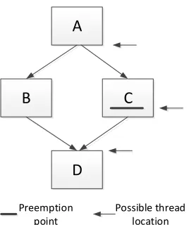
Figure 2.5Possible thread locations when a preemption point is reached.
2.3.2 Architectural State Reduction
We propose to use liveness analysis to reduce architectural register states. Liveness analysis reports
that at any program point, which registers are defined and may be potentially used before the next
re-define. Only the values in live registers need to be saved during context switching. At compile
time, the compiler identifies live vector registers at each instruction and saves the results into a
liveness table. Each entry in the liveness table corresponds to one static instruction and the register
liveness information is encoded into a bit vector.
One option to provide the liveness bit vector at runtime is to load the liveness table to the GPU
when the kernel is launched. At any point of execution, liveness registers can be looked up by the PC
of a thread. The problem of such fine-granularity approach is that to store liveness table may take
huge hardware resource. In our baseline architecture, the maximum register number is 64, meaning
each liveness entry is 8B. For a program with 1K instructions, liveness table will take 8KB storage on
hardware. To avoid the overhead of liveness table, we choose selective points to enable preemption.
In other words, instead of enabling preemption for each instruction, we only enable preemption at
certain selected program points. At each preemption point, a preemption instruction is inserted
with encoded liveness bit vector. At runtime, the liveness bit vector is fetched to the instruction
0% 10% 20% 30% 40% 50% 60% 70% 80% 90% 100%
BP BFS BT CFD DWT HW HS HG KM LK LUD SR PF SC GM
N
o
rm
al
ize
d
R
e
gi
ste
r Si
ze
occupancy live live+warp_cp live+warp_cp+tb_cp
Figure 2.6Normalized register context sizes after liveness analysis and compression.
In our approach, an entire warp will be stopped and handled by the preemption handler if any
thread has reached the preemption point. In the case of thread divergence, the liveness of a whole
warp may be different with the threads which reached the preemption point. As shown in Figure 2.5
are the possible thread locations when a preemption point is reached. For example, one warp has
two threads, T1 and T2. Assume that T1 and T2 diverge at basic block A, T1 executes path B and T2
executes path C. When T2 reaches the preemption point at path C, T1 can be either at the divergence
point (end of A) or the reconvergence point (start of D). In this case, the live vector register for the
preemption point should be the union of all these 3 possible thread locations.
In our compiler, we firstly perform the traditional liveness analysis without considering thread
divergence. Then the divergence and reconvergence points are analyzed based on immediate
post-dominator[Fun09]. At last, the compiler calculates the union of liveness at the original preemption point, the divergence point and recovergence point. Because the thread divergence can only be
determined at runtime, both liveness vector versions are saved. When handling the preemption of
a warp, the SIMT stack will be checked to determine whether there is a divergence. If there is, the
union version is used. Otherwise, the original version is used.
To evaluate the effectiveness of liveness analysis, we count the number of live registers in the
Rodinia benchmarks at runtime. When a warp reaches a preemption point, the total liveness number
is accumulated. Then, the sum is divided by the number of warps. The result is shown in Figure
f o r ( i = 1 ; i <= LOG_H ; i++) { i n t pow = __powf ( 2 , i ) ; i f ( t y % pow == 0 ) {
f l o a t tmp = s_weight[t y+pow/2] [t x ]; s_weight[t y] [t x] += tmp ;
}
__syncthreads ( ) ; }
Figure 2.7A kernel code snippet of BP_1.
0% 20% 40% 60% 80% 100%
R
e
gi
ste
r Pat
te
rn
Pe
rc
e
n
tage
uniform strided random
Figure 2.8Warp-Level register value locality analysis.
per-warp context size is reduced from 1664B to 656B. On average across all the kernels, 34.3% of the
register context size can be reduced with liveness analysis.
2.3.3 Architectural State Compression
Register state compression is based on the observation that many register values in GPU programs
conform certain patterns. S. Collange et al.[Col10]reports that uniform and strided are common patterns for GPU vector registers. A uniform register is defined as all scalar registers in a vector
register have the save value, i.e.Vi =a. A strided register is defined as the scalar registers in a
vector register conform arithmetic progression, i.e.Vi =a i+b. In this paper, we show that the
TB dimension is an important factor for analyzing GPU register pattern. Also, we explore TB-level
register compression to further exploit inter-warp data locality.
Warp-Level Compression
registers. Take the kernel code snippet of BP in Figure 2.7 as an example. BP_1 has 16x16 TB
dimen-sion, tx and ty are the thread ids in the X and Y dimendimen-sion, respectively. The variable i is uniform
across all threads in a warp, and so are the variable pow and the base addresses of array s_weight.
However, for a warp with 32 threads, the values of ty for warp 0 is “0, 0, ..., 0, 1, 1, ..., 1”. The uniform
pattern occurs for 16 scalar registers instead of the whole vector register. A similar situation happens
for tx, which has the values “0, 1, ..., 15, 0, 1, ..., 15” for a warp. So, in this paper, the register pattern
analysis is performed at the granularity of a pattern analyzing group (PAG). PAG is the minimum
between the vector register width and the lowest TB dimension. In our baseline architecture, the
vector register width is 32. So the maximum value of PAG is 32. When one of the TB dimensions is
less than 32, PAG is the lowest TB dimension.
For vector registers containing uniform values, we can compress it into 1 scalar register. A strided
vector register can be compressed to 2 scalar ones, i.e. a base and a stride. We refer to other registers
as random ones, such as tmp in Figure 2.7.
To analyze the warp-level register value locality, we also take samples in the Rodinia benchmarks
at runtime. For each sample, we count how many vector registers are uniform, strided or random
in each warp. We only analyze the live registers. After execution, the average of all the samples is
calculated. Figure 2.8 shows the result. For BP, 47.4% of its live registers are uniform and 52.6%
live registers are strided. Therefore, the per-warp context size can be further reduced to 64B on
average. From Figure 2.6, we can see that on average 91.5% register context size can be reduced with
combined liveness analysis and warp-level register compression.
In our benchmark, BP, HS and LUD has two-dimensional TBs and the PAG is different with the
vector register width. In Figure 2.8 we use two approaches for warp-level register pattern analysis.
The default approach is to use PAG as the analysis width whereas the BP_vec, HS_vec and LUD_vec
use the vector register width, i.e., the warp size, as the analysis width. From the result we can see
that our approach can exploit uniform and strided registers more effectively.
Figure 2.10 shows the logic design for register state compression. The inputs are PAG scalar
0% 10% 20% 30% 40% 50% 60% 70% 80% 90% 100%
BP BT DWT HW HS LUD SR PF
R
e
gi
ste
r Pat
te
rn
Pe
rc
e
n
tage
local uniform global uniform local strided global strided random
Figure 2.9TB-Level register value locality analysis.
first subtraction result will be converted to a Boolean signal a, showing whether the difference is
0. The comparator takes the results of all subtractors and outputs 1 if all the results are equal, 0
otherwise. The output of the comparator is marked as signal b. This way, the signals a and b encode
the value pattern, 01: uniform, 11: stride, 10/00: random. This logic is fully pipelined. Because the vector register width is 32 in our baseline architecture, the maximum of PAG is 32. In our experiments,
the compression latency is assumed as 2 cycles. Such assumption is also used in a similar design for
register compression[Lee15a].
The decompression process is relatively straightforward. For uniform registers, the value is
duplicated PAG times for PAG registers in one warp. For strided registers, the first register takes the
base value, and every following register adds the stride value to the former one.
TB-Level Compression
TB-level compression leverages inter-warp locality for vector registers. For example, in Figure
2.7, all threads across a TB has the same value of i when they are in the same dynamic program point.
Such registers are defined as global uniform. A local uniform register is the registers that have the
same value for PAG threads, e.g. variable ty. Similarly, global strided registers are the registers that are
strided across all threads in a TB. For example, the index of s_weight, which equals tot y ×16+t x,
is global strided. Local strided registers are the registers that are strided for PAG threads but are not
For local uniform/strided registers, the compression is the same as the warp-level compression. For a global uniform register, only one scalar register will be saved for the whole TB. Only two
scalar registers, base and stride, in a TB will be saved for a global strided register. So, for global
uniform/strided registers, the compression ratio is higher than warp-level compression.
Figure 2.11 illustrates the TB-level compression logic. For each logic register, the physical registers
of all warps in a TB are analyzed by the warp-level compressor. The registers will be identified as
random if any physical vector register is random. Then the random registers bypass the compressor
and spill to the global memory. If all the registers are not random, the base and stride are stored in
the base or stride vector buffer. After all warps in the TB finished compressing, the pattern of base
vector and stride vector are analyzed. The registers are global uniform if the base vector is uniform
and the stride vector is zero-uniform, meaning the scalar registers are all zeros. The registers are
local uniform if the stride vector is zero-uniform and the stride vector is not uniform. The registers
are global strided if the base vector is strided, the stride vector is non-zero uniform, and the stride in
the base vector is the same as the stride in the stride vector. Otherwise, the registers are local strided.
In this analysis, the base vector and stride vector width equal toT B_s i z e/P AG.The maximum TB
size is 1024, the minimum PAG we support is 8, and the N in Figure 2.11 is 32 in our implementation.
The TB-level register pattern is shown in Figure 2.9. The approach we use to analysis TB-level
register pattern is similar to warp-level register patterns except that TB-level is only enabled when the
preemption point is a barrier. If the preemption point is not at a barrier, the liveness of different warps
may be different and the register pattern becomes difficult to analysis. So only the benchmarks with
barriers are shown in the result. In Figure 2.6, we apply TB-level compression at barrier preemption
points and warp-level compression for other preemption points. From the result, we can see that
TB-level compression can further reduce register context size by 36.1% on average. However, because
TB-level compression may be worse on some benchmarks, e.g. PF, and it can only be applied on
V0 V1 V2 . . . VPAG-1
. . .
Comparator Bool
a b
Stride Base
PAG registers
Subtractor Subtractor Subtractor Subtractor
Figure 2.10Warp-level register state compression logic.
Warp-level compressor
B0 B2 B3 ... BN-1 S0 S2 S3 ... SN-1
Base vector Stride vector
Local bases Local strides
Global base/stride Random registers
Vector registers
2.4
Context Switching for Preemption
2.4.1 Selective Preemption
As long execution time of a TB mainly results from loops with large numbers of iterations, we insert
one preemption point for each loop. For nested loops, only the innermost loop is considered. For
loops with one barrier, the barrier will be selected as the preemption point. If any other point is
selected as a preemption point, deadlocks may occur when some warps are waiting at the barrier
while other warps reach the preemption points and wait for preemption. The barrier with minimum
liveness is selected by the compiler if there are more than one barrier in the loop. For loops without
barriers, the point with minimum liveness is selected. Outside the loops, we insert one preemption
point every K instructions. Similar to the loops, either the minimum liveness point or the barrier is
selected. If a kernel does not have a loop or a barrier and the kernel is smaller than K instructions,
the execution time of a TB is small and our approach is essentially the same as SM-draining[Tan14]. In our experiment, because the execution time of all benchmarks is dominated by loops, the value
of K does not have a great impact on the evaluation results when it varies from 100 to 1000.
We introduce two preemption point (pp) instructions, bar.pp and pp, to annotate the
preemp-tion points. After analyzing the preemppreemp-tion points, one preemppreemp-tion instrucpreemp-tion is inserted to one
point. For preemption point at barriers, bar.pp instruction is inserted to replace the original barrier
instruction. bar.pp is a barrier instruction when the preemption signal is off. For the other
preemp-tion points, pp instrucpreemp-tions are inserted into the program. The pp instrucpreemp-tion becomes a nop when
the preemption signal is off. When a preemption signal is on, warps keep running until a preemption
point is reached. Then the warp stops and waits for preemption.
Both preemption instructions have one operand to provide the liveness bit vector for the program
points at which the instructions are inserted. To follow the Fermi ISA format[Asf] [NVI], 10 bits are reserved as opcode. The remaining 54 bits are used as liveness bit vector. Because the architecture
may support more than 54 registers, the highest bit is used to denote there are live registers that have
TBC[0]
rf_ptr
reg_pat[N] reg_val[N]
Context control block
TBC[1] ... TBC[M-1]
smem TB context
sstack[N]
smem_ptr sstack_ptr
Figure 2.12Kernel context format.
we observe that a 53-bit vector is typically enough for representing the liveness. To provide the
liveness for thread divergence, a dummy instruction is introduced and it follows the pp instruction.
It also encodes 54 bits for the liveness bit vector. At runtime, if thread divergence is detected at the
preemption point, the liveness which is encoded in the dummy instruction is used for preemption.
The bar.pp instruction doesn’t need to be followed by the dummy instruction because the barrier
ensures that there should be no divergence[NVI15].
2.4.2 Context Format
Due to the in-place context switching as we discussed in Section 2.3.1, register file and shared
memory can either be reserved on SM or dumped to global memory. In this paper, the context
switching granularity is TB, meaning that the register file or shared memory of one TB cannot be
partly spilled. But shared memory and that register file of one TB can reside in different locations,
one in SM and the other in global memory, as illustrated in Figure 2.4.
As shown in Figure 2.12 is the context format of a kernel. The context control block (CCB) contains
an array of TB context. The array size M is the maximum number of TBs that can be launched on
the processor. Each entry contains the global memory pointers for the context of the register file,
shared memory and SIMT stack. The pointer is NULL if the register file or shared memory is in-place
reserved. Otherwise, a global memory space is allocated. The shared memory size on global memory
Context saving logic Compressor
Context restoring logic Decompressor
Pattern vector
RF/Smem allocation table RF/Smem
read port
RF/Smem write port
Global write port
Global read port Liveness bit vector
Figure 2.13Saving and restoring pipelines for preemption.
N equals to the warp number in one TB. The register context size for each warp is the maximum
liveness number times vector register width. To maximize the bandwidth usage, the compressed
register values are stored continuously. For decompressing, a pattern vector is used to store the
register pattern and liveness of a warp. Two bits are used to represent the four states of each register.
The four states are uniform, strided, random and dead. Because the maximum register number is
64, so the pattern vector length is 128 bits. In our paper, the whole SIMT stack will be saved to global
memory. Because the SIMT stack includes the PC for each thread, the PCs are not separately saved.
The warp is waiting at a barrier if the PC points to a barrier instruction, so the barrier state of each
TB can also be derived from the SIMT stack.
2.4.3 Preemption Pipeline
Because the executions on different SMs are independent, a new kernel may preempt all SMs or
only some of them. Here, we focus on preemption in one SM. When an SM receives an interrupt
signal for preemption, the active warps keep executing until a preemption point is reached. Then
the reached warp is set as inactive so that they will not fetch or issue new instructions. In order to
preserve precise states, a warp must be drained before being switched out. A drained warp means
that it has no issued instructions in the pipeline and has no pending updates to the register file.
As shown in Figure 2.13 is the spilling and restoring pipeline for preemption. For saving the
context, the context saving logic looks up the register and shared memory allocation table, shown
Table 2.1Baseline architecture configuration
Num. of SMs 15
SIMT core freq. 700MHz
Warp size 32
SIMD width 32
Resources per SM 8 TB slots, 48 warp slots (1536 threads), 128KB register file, 48KB shared memory
Warp scheduler 2 schedulers, RR policy
L1 D-cache 16KB per SM, 128B block size
L2 cache 128KB per channel, 6 channels
DRAM 924MHz, QDR, 384-bit bus, peak bandwidth=0.924*4*384/8
=177GB/s
to global memory in order to accommodate the new kernel. Such information is converted to how
many resident TBs to be spilled. To save the register of a warp, the liveness vector is fetched from the
instruction buffer. Then the live vector registers are compressed and pushed into a buffer. Because
the most efficient way to access global memory is by a width of 128B, the compressed data form
data segments with the size of 128B through the buffer. After the register states of all warps from
one TB are drained, shared memory used by this TB starts to be spilled to global memory.
To restore a TB, the restoring logic waits for there is enough on-chip resource to launch the TB.
Then the context control block, shown in Figure 2.12, is accessed to find the TB context. To restore
the registers of a warp, the pattern vector is firstly loaded. Then each vector register is decompressed
based on its pattern.
2.5
Experiments
2.5.1 Methodology
We implemented our lightweight context switching on GPGPU-sim[Bak09]v3.2.2. Our baseline architecture models the NVIDIA GTX480 GPU, and its configuration is shown in Table 2.1.
GPGPU-sim supports both the PTX and GT200 instruction set architecture (ISA). PTX is for a virtual machine
with unlimited registers. Therefore, in order to collect the accurate architectural register information,
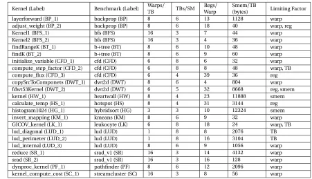
Table 2.2Benchmark specification
Kernel (Label) Benchmark (Label) WarpsTB / TBs/SM Regs/ Warp
Smem/TB
(bytes) Limiting Factor layerforward (BP_1) backprop (BP) 8 6 13 1128 warp
adjust_weight (BP_2) backprop (BP) 8 6 18 40 warp, reg
Kernel1 (BFS_1) bfs (BFS) 16 3 7 44 warp
Kernel2 (BFS_2) bfs (BFS) 16 3 4 36 warp
findRangeK (BT_1) b+tree (BT) 8 6 10 48 warp
findK (BT_2) b+tree (BT) 8 6 9 60 warp
initialize_variable (CFD_1) cfd (CFD) 6 8 6 32 warp compute_step_factor (CFD_2) cfd (CFD) 6 8 8 48 warp, TB compute_flux (CFD_3) cfd (CFD) 6 4 39 36 reg copySrcToComponets (DWT_1) dwt2d (DWT) 8 6 4 804 warp fdwt53Kernel (DWT_2) dwt2d (DWT) 6 5 32 8668 reg, smem kernel (HW_1) heartwall (HW) 8 4 23 11888 smem calculate_temp (HS_1) hotspot (HS) 8 4 31 3144 reg histogram1024 (HG_1) hybridsort (HG) 3 3 10 12324 smem invert_mapping (KM_1) kmeans (KM) 8 6 9 32 warp GICOV_kernel (LK_1) leukocyte (LK) 6 8 18 24 warp, TB lud_diagonal (LUD_1) lud (LUD) 1 8 8 2076 TB lud_perimeter (LUD_2) lud (LUD) 1 8 16 3104 TB lud_internal (LUD_3) lud (LUD) 8 6 9 1056 warp reduce (SR_1) srad_v1 (SR) 16 3 14 4132 warp srad (SR_2) srad_v1 (SR) 16 3 16 128 warp dynproc_kernel (PF_1) pathfinder (PF) 8 6 12 2096 warp kernel_compute_cost (SC_1) streamcluster (SC) 16 3 8 56 warp
benchmarks. Table 4.2 lists all the benchmarks. Each entry in Table 4.2 shows the information of
a kernel. Because some benchmarks (e.g., BP) contain multiple kernels, (e.g., BP_1 and BP_2), we
combine the results of these kernels in our evaluation.
We model the potential traffic contention due to context switching at register read/write ports, shared memory read/write ports, the interconnect to memory controllers, and memory read/write bandwidth. For preemption, we found that the contention is limited as the SM essentially stops
execution and all the ports are used for context swapping. The context switching requests have
lower priority than regular requests from instruction execution.
To evaluate the preemption performance, we add periodic preemption signals (every 10000
cycles) when running the benchmarks. We run each benchmark for at most 200 million cycles or
until it exits. When a preemption signal is received, one SM stops running and spill its architectural
states to global memory while other SMs keeps running, the same method as used in prior works
0% 20% 40% 60% 80% 100% o cc u p liv e liv e+ cp o cc u p liv e liv e+ cp o cc u p liv e liv e+c p o cc u p liv e liv e+ cp o cc u p liv e liv e+c p o cc u p liv e liv e+ cp o cc u p liv e liv e+c p o cc u p liv e liv e+ cp o cc u p liv e liv e+c p o cc u p liv e liv e+ cp o cc u p liv e liv e+ cp o cc u p liv e liv e+ cp o cc u p liv e liv e+ cp o cc u p liv e liv e+ cp
BP BFS BT CFD DWT HW HS HG KM LK SR PF SC GM
N o rm al iz e d Sp ill in g La te n cy
register shared memory SIMT stack
Figure 2.14Normalized spilling latency.
0% 20% 40% 60% 80% 100% 120% 140% 160% 180% 200% o cc u p se le ct SM _d ra in o cc u p se le ct SM _d ra in o cc u p se le ct SM _d ra in o cc u p se le ct SM _d ra in o cc u p se le ct SM _d ra in o cc u p se le ct SM _d ra in o cc u p se le ct SM _d ra in o cc u p se le ct SM _d ra in o cc u p se le ct SM _d ra in o cc u p se le ct SM _d ra in o cc u p se le ct SM _d ra in o cc u p se le ct SM _d ra in o cc u p se le ct SM _d ra in o cc u p se le ct SM _d ra in
BP BFS BT CFD DWT HW HS HG KM LK SR PF SC GM
N o rm al iz ed P reem p ti o n L aten cy spill drain
213% 4251% 1925% 4719% 214% 7667% 270%
Figure 2.15Normalized preemption latency.
2.5.2 Spilling Latency
In Figure 2.14, we evaluate the normalized latency for spilling the architectural states to global
memory. Three approaches are compared to show the effectiveness of liveness analysis and register
compression. ‘Occup’ shows the latency to spill all the occupied architectural states. The spilling
latency is measured from interrupt signal is issued to all the states are spilled. ‘Live’ is to spill only
the live registers and ‘live+cp’ is to spill the live registers with warp-level register compression. For ‘live’ and ‘live+cp’, the latency for the spilling registers of a warp starts from the preemption point is reached. Then the latencies of all warps are accumulated. For each mechanism, the normalized
latency to spill register file, shared memory and SIMT stack are evaluated.
If we see the results of ’Occup’, the spilling latency of most benchmarks (except for HG) is
dominated by spilling the registers. This is because the register file is the largest on-chip memory
that stores the architectural states and it has relatively high occupancy (Figure 3.7). For DWT, HW and
for these benchmarks is high (Figure 3.7). For most benchmarks, the SIMT stack spilling latency is
too small to be observed. The SIMT stack latency appears for BFS because its live register number is
very small.
From the results, we can see that liveness analysis and register compression drastically reduce the
latency to dump the register state. Since shared memory size is not reduced by these two mechanisms,
the latency for saving shared memory states is similar for different approaches. The geometric mean
for spilling total architectural states is reduced to 17.7%. With the GPU core frequency of 700Hz,
the average spilling latency is reduced from 9.9us to 1.8us. In the special case of BFS, the spilling
latency is increased with ‘live+cp’ compared to ‘live’. The reason is that no live registers can be compressed at the preemption points and our preemption mechanism needs to store metadata for
the compression patterns of the registers. Therefore, the data to be saved become larger for BFS
when compression is enabled.
2.5.3 Preemption Latency
The preemption latency evaluation is shown in Figure 2.15. The results are normalized with spilling
all occupied architectural states to global memory. ‘Select’ shows the selective preemption latency
with register liveness analysis and compression. The total preemption latency is measured from
the start of preemption signal to the architectural states are spilled. The latency labeled as ‘spill’ is
the context spilling latency. With selective preemption, the warps keep executing until preemption
points are reached. So, for some time the spilling pipeline is idle to wait for warps reaching the
preemption points. Such latency is called draining latency and labeled as ‘drain’. Because
SM-draining lets all current TBs to finish, it doesn’t need to save any architectural states for these
TBs.
Compared with the baseline, the preemption latency is reduced to 40.3% on average (geometric
mean). With the GPU core frequency of 700Hz, the preemption latency is reduced from 9.9us to
4.0us. The draining latency accounts for 55.8% of the selective preemption latency. Note that during
1 1.5 2 2.5 3 3.5 4
N
o
rm
al
ize
d
Wo
rst
Case
Pr
e
e
m
p
tio
n
La
te
n
cy occupancy select drain
Figure 2.16Normalized worst case preemption latency
For SM-draining, although the SM keeps doing useful work during preemption, the latency
becomes unbearable for many benchmarks. For example, the average preemption latency for LK
is 1431.1us. The newly incoming kernel would have to wait for such long TBs. As a result, fairness
cannot be guaranteed with SM-draining because it favors kernels with long TBs. With selective
preemption, because the preemption is guaranteed to be done in every loop iteration or every 1000
instructions, the draining latency is much more manageable.
2.5.4 Worst Case Preemption Latency
Because selective preemption has to wait for the warps to execute some instructions before being
spilled, the latency variation may become higher than naive approach. To evaluate the preemption
latency in the worst case scenario, we select 12 kernels which can run long enough to generate 15
times preemption signals. As shown in Figure 2.16, for each mechanism, the worst case preemption
latency is normalized to its average latency. From the results, we can see that the naive approach,
which is saving all occupied states, has 0.4x difference between average and worst case scenario. The
difference may result from the different instructions to drain before preemption or the difference of
memory traffic. For selective preemption, the difference between average and worst case scenario
is 0.6x, which is slightly higher than the naive approach. The worst case latency for SM-draining
is 2.4x compared with the average. For SM-draining, the worst case happens when an interrupt is
0% 10% 20% 30% 40% 50% 60% 70% 80% 90% 100% co mp le te in p lac e co mp le te in p lac e co mp le te in p lac e co mp le te in p lac e co mp le te in p lac e co mp le te in p lac e co mp le te in p lac e co mp le te in p lac e co mp le te in p lac e BT_1-HG_1 PF_1-HW_1 LK_1-BP_1 SR_1-BP_2 CFD_3-BFS HS_1-KM_1 HW_1-HG_1 SC_1-HW_1 GM N o rm ali ze d P e e m p tio n Lat e n cy spill drain
Figure 2.17Normalized preemption latency with in-place context switching
2.5.5 Impact of In-Place Context Switching
To evaluate in-place context switching, we randomly pick 8 pairs of kernels which are labeled as
‘kernel1-kernel2’ in Figure 2.17. We assume that ‘kernel1’ is preempted by ‘kernel2’ and measure the
switching out latency for ’kernel1’. The baseline, which is labeled as ‘complete’, is the preemption
latency of the approach using both liveness analysis and compression. For in-place context switched
warps, they still have to reach the preemption point until being handled by preemption pipeline.
As a result, the warps still need to be drained even if there is no register to spill, e.g. BT_1-HG_1.
From the figure, we can see that the latency for spilling the register and shared memory states can
be further reduced with our proposed in-place context switching, by 21.5% on average. On some
benchmarks, e.g. BT_1-HG, The draining latency is higher on in-place context switching. This is
because spilling can hide the latency for some warps to drain.
2.6
Related Work
On CPUs, there are many works focusing on context reduction to reduce the preemption overhead
and improve processor utilization. Some works[Sny95] [ZP06]propose to seek program points with small numbers of live registers for context switching, thereby reducing the context switching
contexts is very fast, and multiple contexts can tolerate long latencies from cache misses.
To enable fast context switching and exception handling on GPUs, iGPU[Men12]partitions kernel code into idempotent regions and each region is a recovery point. iGPU also leverages liveness
analysis when formatting recovery points for context reduction. Register liveness is also used for
dynamic register file management[Jeo15]. Lee et al.[Lee15a]leverage register compression for reducing GPU power. They use the base-delta-immediate (BDI) compression algorithm[Pek12] for register file compression. BDI separates a vector register into several trunks and stores the
value of first chunk and the delta between adjacent chunks. As delta values tend to be very small,
they can be stored in small bins. The compression technique is used for the register file and every
each register read/write needs to be decompressed/compressed. In comparison, we only perform compression/decompression when a context is spilled/restored.
Some recent works aim to enable the preemption on GPU. RGEM[Kat11]is a user-space solution to reduce the response time of high priority kernels. It splits the input data into multiple chunks
so that a kernel can be preempted at a chunk boundary. PKM[BK12]partitions the overall TBs of a kernel into multiple sets where each set has a specific number of TBs. Softshell[Ste12]is a GPU programming model which supports a kernel being preempted at the boundary of TBs. In
comparison, our proposed approaches enable efficient preemption at the instruction granularity.
Concurrent kernel execution is another option to support GPU sharing by multiple kernels.
KernelMerge[Gre12]and Spacial Multiplexing[Adr12b]study how to use concurrent kernels to better utilize GPU resources and improve overall throughput. Elastic kernel[Pai13]increases GPU utilization by issuing concurrent kernels on one SM. After TBs from one kernel are issued to the
SM, the spare resources are distributed to another kernel. In[Lee14], Lee et al. also leverage mixed concurrent kernels to improve GPU utilization.
Compared to these prior works, the novelty of our work includes (a) fast context switching
2.7
Conclusions
In this paper, we present lightweight context switching for GPUs and compiler-hardware co-design
to enable efficient preemption. We propose three schemes, in-place context switching, liveness
analysis and register compression, to address the problem of the large kernel context on GPUs.
Our results show that with register liveness analysis and compression, the register context can
be reduced drastically by 91.5%. With selective preemption enabling instructions, we can achieve
efficient instruction-level preemption with an average preemption latency of 4.0us (with the 700MHz
CHAPTER
3
GPU PERFORMANCE VS. THREAD-LEVEL
PARALLELISM: SCALABILITY ANALYSIS
AND A NOVEL WAY TO IMPROVE TLP
3.1
Introduction
State-of-the-art throughput-oriented processors, like GPUs, have become the dominant accelerator
for data-parallel workloads. To achieve high computation throughput and memory bandwidth,
0 20 40 60 80 100 120 140 0% 10% 20% 30% 40% 50% 60% 70% 80%
1 2 4 8 16 24 32 48 64
IP C L1 H it R at e / D R A M B W U ti liz a ti o n
Number of Active Warps
L1 hit rate DRAM BW IPC
Figure 3.1Instruction per cycle (IPC), L1 D-cache hit rate and DRAM bandwidth utilization with different numbers of active warps for the SPMV benchmark.
one ready instruction among multiple warps every cycle. Such fine-grain multithreading is the
key to hide the memory latency. As a result, GPUs feature high amounts of on-chip resources to
accommodate the contexts of large numbers of concurrent warps. For example, in the NVIDIA
GP100 (Pascal) architecture[Pas], each stream multiprocessor (SM) has a 256KB register file and accommodates up to 64 warps.
The inclusion of multipl