Jurnal Teknologi, 42(D) Jun. 2005: 55–64 © Universiti Teknologi Malaysia
1,2&3
Process Tomography Research Group (PROTOM), Control & Instrumentation Engineering Department, Faculty of Electrical Engineering, Universiti Teknologi Malaysia, 81310 UTM Skudai, Johor, Malaysia.
* Corresponding author: E-mail: [email protected]
ETHERNET BASED OPTICAL TOMOGRAPHY SYSTEM
RUZAIRI ABDUL RAHIM1*, GOH CHIEW LOON2 & CHAN KOK SAN3
Abstract. Optical tomography is one of the methods of process tomography, which is less expensive, has a better dynamic response and is more portable for routine use in process plant than other radiation-based tomographic methods. The main objective of this research is to optimize the performance of the optical sensors by increasing the data transfer rate from hardware to personal computer.
Keywords: Optical tomography, ethernet, window socket, data acquisition system, parallel beam
Abstrak. Tomografi optik ialah salah satu cara dalam tomografi proses yang mana ia adalah kurang mahal, mempunyai balasan dinamik yang lebih baik dan lebih mudah alih untuk penggunaan dalam tempat pemprosesan berbanding dengan cara tomografi berasaskan radiasi yang lain. Objektif yang paling diutamakan dalam penyelidikan ini adalah untuk mengoptimumkan perlaksanaan optik dengan mempercepatkan kadar penghantaran data dari perisian keras kepada komputer.
Kata kunci: Tomografi optik, ethernet, window socket, data acquisition system, parallel beam
1.0 INTRODUCTION
Process tomography is a measurement technique that is being developed for measurement in two and multi component flows to visualize the internal cross section of a pipeline. It involves using tomography imaging methods to manipulate data from remote sensors [1]. Image reconstruction of a flow is essential for a more advanced investigation of mass flow rate measurement in a certain tomography process. Process tomography is divided into many fields such as electrical capacitance tomography, optical tomography, ultrasonic tomography, and others. Optical tomography is one of the methods of process tomography which is less expensive, has a better dynamic response and is more portable for routine use in process plant than other radiation-based tomographic methods.
using Ethernet as the connection between hardware and personal computer (PC) has been carried out for the purpose of reducing the cost.
Parallel beam optical tomography’s sensors can provide infinite sets of data whereas data obtained from fan beam optical tomography system is limited by the sensors’ switching time. Therefore, in this research, a parallel beam optical tomography system will be developed to optimize the transfer rate of an optical tomography system. The main objective of this research is to optimize the performance of the optical sensors by increasing the data transfer rate from hardware to PC, increase the resolution of image reconstruction by having more projections of light through the proposed pipeline, increase the ability to scan smaller particles with projection geometry in one layer by combining two orthogonal and two rectilinear projections, increase the data or image processing time by using Visual C++ programming platform and derive a suitable data reconstruction algorithm for visualizing the cross-sectional image and mass flow rate measurement of the proposed pipeline.
2.0 OPTICAL TOMOGRAPHY SYSTEM
Optical tomography involves projecting a beam of light through some medium from one boundary point and detecting the level of light received at another boundary point [2]. Basically, optical tomography system can be subdivided into four sub-systems: the sensing array, the signal conditioning system, the data acquisition system, and the image reconstruction and display system. For the projection geometry, optical tomography includes two main sensor arrangements which are the parallel beam optical tomography and fan beam optical tomography.
At one particular scanning angle, a single source illuminates its associated detectors simultaneously and the detectors corresponding to various angles collect the data. These are termed fan beam projection [3]. In parallel beam optical tomography, arrangement is in two orthogonal projections, two rectilinear projections, or combination of two orthogonal and two rectilinear. Previous research had been carried out by [4], in which 8 × 8 pairs of sensor were used in two orthogonal projections and another 11 × 11 pairs of sensor were used for two rectilinear projections. Pang improved the hardware resolution by doubling the number of sensor pairs used in both the orthogonal (16 × 16 pairs) and rectilinear projections (23 × 23 pairs) [5]. The major difference between the current and previous research is the number of involved sensor layer. In the previous research, orthogonal projections and rectilinear projections were in different layer, and assumption that both the orthogonal and rectilinear were to be in one layer had been made. In this research, the above assumption is not required due to the fact that the two orthogonal projections and two rectilinear projections are combined into one layer.
to the intensity of the detected light. The output signal from each photo-detector is dependent on the position of the component boundaries within their sensing zones. The generated current is being converted, amplified and then transferred into the computer through a data acquisition system. Using certain data reconstruction and image display algorithm, tomogram and mass flow rate measurement can be obtained.
2.1 Optical Sensors
In the sensor sub-system, optical sensors will be used to project several beam of light. A Light Emitting Diode (LED) is a solid-state semiconductor which emits a small amount of light when current flows through it in the forward direction. Infrared light (IR) is light with wavelengths from 800 nanometers up to 3 micrometers. In the market, there is a wide range of optical sensors to choose from. An optical sensor can consist of a phototransistor, photodiode, photomultiplier, photocells, CDC photocells or a photo-resistor as the receiving sensor. The criterions of selecting optical sensors depend on the application and requirement of the proposed system. Selection of the suitable photo detectors is based on its electrical characteristics such as the available wavelengths, performance-to-cost ratio, sensitivity, linearity, physical size, dynamic range and ambient noise performance.
2.2 Signal Conditioning Circuit
The principle of an optical tomography system is to investigate the light attenuation level for each detector. Basically, a light radiation measurement device consists of a photo detector, a current to voltage converter (pre-amp), a voltage amplifier, noise reduction and a voltage comparator circuit. The obtained measurement depends on the particle flow rate and individual path length of sensor within the pipeline. In other words, the more particles that intersect a light beam, the greater the output signal.
2.3 Data Acquisition System
bytes per second. The problem with RS232 communications is that it requires a hard wired, point-to-point cable connection that is limited in the distance. RS232 links can be 80 feet or more, with the exact limit depending on the cable specifications and the speed of data transfer.
Another new option for I/O interfacing is the USB, which can have up to 127 devices communicating at either 1.5 Megabits/second or 12 Megabits/second over a 4-wire USB cable. USB requires a relatively complex device to handle the protocols, and the development learning curve can be steep, even with supplied toolkits. Some micro-controllers have USB facilities incorporated, but the overhead takes a sizeable chunk of their total computing power. USB peripherals must also be situated not too far from the PC. It is not practical to hang too many USB devices off a PC as they will be sharing time. All USB devices have to share a 1mS time slot broadcast from the PC, and all replies must fit within this time slot. For example, a USB sound card can easily take up most of the bandwidth. Data transfer rates can be a lot less than advertised. IrDA (Infrared Data Association) interface allows wireless serial communications over distances of 3 to 6 feet. The link transmits infrared energy at up to 115,200 bits/second. It’s intended for convenient (no cables or connectors) transmitting of files between a desktop and laptop computer, or between any short-range communications where a cabled interface is inconvenient. However, only laptops and palmtops offer IrDA as standard. Ordinary PCs will require an extra hardware module interface with an infrared sensor and light.
In this research, Ethernet communication protocol is chosen as the link between hardware and PC. There is no restriction on the length of the cable (as long as 4000 feet) to be used and it would remain 100% compatible with all currently available Ethernet communications software. Besides that, Ethernet allows high speed data transfer rate, which is up to 10 Megabits/second. The main disadvantage of a network solution is the complexity of the interface hardware/firmware [6]. The interface must handle all the relevant protocols. On the plus side, a network solution has many advantages, communication device can be located anywhere (not near the computer), and even at a remote location. It can be driven from any computer on the network because of no special software drivers.
3.0 ETHERNET TECHNOLOGY
network; they simply wait for a suitable gap in the network traffic. Ethernet blocks are called frames, all data on the network is in frames with a defined beginning and end and integrity check through cyclic redundancy check (CRC). Ethernet is a Carrier Sense Multiple Access with Collision Detection (CSMA/CD) network which if a collision is detected during data frame transmission, a brief jamming signal will be transmitted to assure that there has been a collision and thus cease transmission. The Ethernet system consists of three basic elements, the physical medium used to carry Ethernet signals, a medium access control rules embedded, also terms as protocol in each Ethernet interface, and an Ethernet frame.
Writing a network application would not be feasible if the application developer have to understand all the details of accessing communication links and include the ability to access multiple kinds of transmission media. The solution to this issue is the Transmission Control Protocol/Internet Protocol (TCP/IP) network protocol stack, which provides applications with a higher-level interface for accessing the network [8]. Several levels of network functionality are implemented within the protocol stack, including link access, internet work routing, and insuring reliability. Protocol is the specification and exact format of data exchanged between two entities. Besides TCP/ IP stack, other protocol stacks widely used on local computer networks are Netware Stack and NetBEUI stack. However, network communication can only occur between machines running the same protocol stack. TCP/IP is the most widely used protocol stack and is implemented on most computer platforms.
3.1 Window Socket (WinSock) Programming
Window Socket is an application program interface (API) specification defining program calls used to access network functionality [8]. Window Sockets or WinSock, as it is most commonly referred to, is an open specification. Thus it allows for independent development of network applications and network protocol stack software products. The Window Sockets specification defines an application binary interface (ABI) for access to the TCP/IP protocol stack in a Windows or Windows NT environment. WinSock programming maintains exactly the same procedure calls as Berkerly sockets.
4.0 HARDWARE DEVELOPMENT
Figure 1 shows the block diagram of the system. It consists of four parts, which are the sensing array, the signal conditioning system, the data acquisition system, and data reconstruction and image display system.
projections in one layer. Infrared emitters (IR LED) were chosen to transmit light due to the fact that there is a requirement for high optical penetrating power in the optical tomography system. Infrared LEDs emit more light intensity, as compared to visible LEDs. The photodiode was chosen over phototransistor because of its linearity, and faster response. Furthermore, a photodiode produces lower noise due to no gain in photodiode. The gain of phototransistor leads to the amplification of noise. The HSDL 5420 photodiode manufactured by Agilent was chosen as the receiver, whereas TSHA 4401 manufactured by VISH was chosen as the photo emitter. Both of the sensors’ wavelengths are 875 nm and lens size are 3 mm.
Emitter driving circuit falls into three main categories: DC driving, AC driving (including modulation systems) and pulse driving system. In the parallel beam optical tomography system, it is very important to choose a driving system which can stabilize the radiant flux of LED, provide the large radiant flux with less influence of disturbing light and maximize the intensity of light. DC driving circuit with a constant current was constructed. The photodiodes’ signals were then flown into the current-to-voltage conversion and amplifying circuit to provide linear conversion. The sensors arranged in rectilinear configuration were used for the masking process, where a “High” signal indicates that particles exist in the ray path of that particular emitter and receiver pair; “Low” signal indicates no particle exists in the ray path of corresponding sensor pair. Due to this masking purpose, the amplified signals from the rectilinear configuration will be fed into a voltage comparator.
In the microprocessor and Ethernet controller based data acquisition system, two tasks will be performed. First, the amplified signals from the orthogonal sensor will be converted to digital signals by using analogue-to-digital converters (ADC). In order to increase the performance of the system, the analogue-to-digital converter needs to have a fast response and high speed analogue-to-digital conversion. The outputs from ADC will then be stored in the memory of a microprocessor. In the case of this research, a Rabbit microprocessor had been chosen to control the signal conversions and drive the Ethernet controller. In the second task, a Rabbit microprocessor will act as a client
Sensor array Signal conditioning
system
Data acquisition system
Data reconstruction & image display system
to request a connection to the PC. Once the connection is accepted by the PC, which acts as server, the connection between the hardware and PC has been established. Thus, RTL 8019 Ethernet controller will transmit data in frames to PC through an Ethernet cable (10 Base T). Client/Server Model was carried out using WinSock Programming. TCP protocol in the TCP/IP network protocol stack was selected in this network communication instead of UDP protocol due to the fact that TCP application is connection-oriented and thus data transmitted is lossless.
As for the data reconstruction and image display system, a new data reconstruction method will be carried out. The signals from the rectilinear sensor will be used as a masking process to investigate existence of particles in the ray path of sensor pair. Signals from the orthogonal sensors will be reconstructed as tomograms. Visual C++ was chosen as the programming platform due to its fast processing time, and it also supports powerful API functions [8].
4.1 Design Core of Data Acquisition
The Rabbit 2000 microprocessor and Realtek Full-Duplex Ethernet Controller RTL8019AS have been used as the main components of the data acquisition system. Dynamic C which is part of the C programming software was used to write the code for Rabbit Core module. Several experiments had been carried out to test the function of the Rabbit 2000 microprocessor.
4.2 Ethernet Communication between Hardware and PC
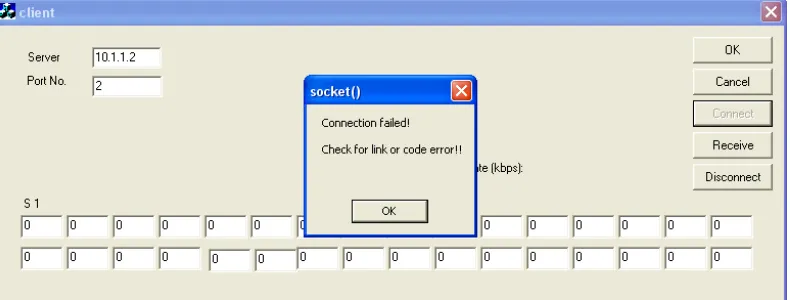
Basic Client/Server had been modeled in microprocessor and PC respectively. Therefore, basic Ethernet communication which enables the transmission of data from hardware to PC is established. The results are shown in Figures 2 and 3. Figure 2 shows that connection failed due to link error, where no hardware was found at the
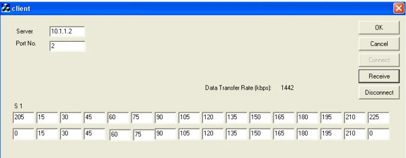
Ethernet port. Figure 3 shows the successful connection between the PC and Rabbit Core module hardware. The client application listens to server 10.1.1.2 and port 2 (which initially set to Rabbit Core module), and the result shows that simulation data in Rabbit Core module transmitted in PC with a data transfer rate of 1442 kbps. Investigation on optimizing the data transfer rate will be done after the hardware circuit has been constructed.
Figure 3 Successful connection between the hardware and the PC with a data transfer rate of 1442 kbps
5.0 RESULTS
Experiments had been carried out to test suitable infrared sensors. The HSDL 5420 photodiode manufactured by Agilent was chosen as the receiver, whereas TSHA 4401 manufactured by VISH was chosen as the photo emitter. Both of the sensors' wavelengths were 875 nm and the lens size were 3 mm.
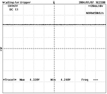
Figure 4 Photodiode response in the daylight Figure 5 Photodiode response inside the pipeline
(1)
(2)
Figure 6 Photodiode response while full light emission of infrared emitter inside the pipeline
Figure 7 Response of Photodiode (1) and comparator (2) when blocking and non-blocking inside the pipeline
6.0 CONCLUSION
REFERENCES
[1] Abdul Rahim, R. 1996. A Tomographic Imaging System for Pneumatic Conveyors Using Optical Fibres. Ph. D. Thesis. Sheffield Hallam University.
[2] Chan, K. S. 2002. Real Time Image Reconstruction for Fan Beam Optical Tomography System. M. Sc. Thesis. Universiti Teknologi Malaysia.
[3] Ibrahim, S., R. G. Green, K. Dutton, R. Abdul Rahim, K. Evans, and A. Goude. 1999. Optical Fibres For Process Tomography: A Design Study. 1st World Congress on Industrial Process Tomography. Buxton, Greater Manchester.
[4] Ibrahim, S. 2000. Measurement of Gas Bubbles in a Vertical Water Column Using Optical Tomography. Ph. D. Thesis. Sheffield Hallam University.
[5] Pang, J. F. 2004. Real-time Velocity and Mass Flow Rate Measurement Using Infrared Tomography. M. Sc. Thesis. Universiti Teknologi Malaysia.
[6] Lau, K. H. 2003. Design of a TCP/IP Based General Purpose Embedded Fuzzy Logic Controller System. B. Sc. Thesis. Universiti Teknologi Malaysia.
[7] Stallings, W. 2000. Data and Computer Communications. United States: Prentice Hall: 592-635. [8] Bonner, P. 1996. Network Programming with Windows Sockets. United States: Prentice Hall: 128-140. [9] Ooi, Y. P. 2000. Image Reconstruction Algorithm for Optical Tomography Using Microsoft Visual C++. B.