AT&T
AT&T 555-620-144 Issue 1
October 1992
MERLIN LEGEND™
Communications System
Release 2.0
Copyright © 1992 AT&T All Rights Reserved
Printed in U.S.A.
AT&T 555-620-144 Issue 1 October 1992
Notice
Every effort was made to ensure that the information in this book was complete and accurate at the time of printing. However, information is subject to change.
Federal Communications Commission (FCC)
Electromagnetic Interference Information
This equipment has been tested and found to comply with the limits for a Class A digital device, pursuant to Part 15 of the FCC Rules. These limits are designed to provide reasonable protection against harmful interference when the equipment is operated in a commercial environment. This equipment generates, uses, and can radiate radio frequency energy and, if not installed and used in accordance with the instruction manual, may cause harmful interference to radio communications. Operation of this equipment in a residential area is likely to cause harmful interference, in which case the user will be required to correct the interference at his own expense.
Canadian Department of Communications (DOC)
Interference Information
This digital apparatus does not exceed the Class A limits for radio noise emissions set out in the radio interference regulations of the Canadian Department of Communications. Le Présent Appareil Numérique n’émet pas de bruits radioélectriques dépassant les limites applicable aux appareils numériques de la class A prescrites dans le Règlement sur le brouillage radioélectrique édicté par le ministère des Communications du Canada.
Trademarks
MERLIN LEGEND is a trademark of AT&T in the U.S. and other countries.
Support Telephone Number
AT&T provides a toll-free customer Helpline (1-800-628-2888) 24 hours a day
Contents
About This Book
1■ Conventions 2
■ Product Safety Labels 3
■ Related Documents 4
■ How to Comment on This Document 6
Introduction
■ System Programming Console 8
■ Programming Information 12
■ Idle States 77
1
Basic System Operating Conditions
1-1■ System Restart 1-2
■ System Programming Position Assignment 1-3
■ System Language 1-5
■ Board Renumbering 1-6
■ Mode of Operation 1-7
■ Automatic Maintenance Busy 1-9
■ System Date 1-11
■ System Time 1-12
Contents
2
System Renumbering
■ Select System Numbering Plan
■ Single Renumbering
■ Block Renumbering
■ Direct Station Selector (DSS) Page Buttons
2-1 2-3 2-5 2-7 2-9
3
System Operator Positions
■ QCC System Operator Positions
3-1 3-4
4
Lines and Trunks
4-1■ ■ ■ ■ ■ ■ ■ ■ ■ ■ ■
Type of Trunk
Outmode Signaling for Loop or Ground Start Trunks Rotary Trunk Digit Transfer
Disconnect Signaling Reliability Toll Type
Hold Disconnect Interval
Principal User for Personal Line QCC Queue Priority Level QCC Operator to Receive Calls Trunks to Pools Assignment Copy Options for Lines/Trunks
4-2 4-3 4-5 4-6 4-8 4-10 4-12 4-14 4-16 4-18 4-20
Contents
5
DS1 Facilities
Type of DS1 Facility
■
■
■
■
■
■
■
Frame For Zero Code
5-1 5-2
mat 5-5
Suppression 5-6
Signaling Mode 5-7
Line Compensation 5-8
Clock Synchronization 5-9
Channel Service Unit 5-10
6
Tie Trunks
6-1■
■
■
■
■
■
■
Direction 6-2
Tie Trunk Type 6-3
E&M Signal 6-5
Dial Mode 6-6
Tie Trunk Dial Tone 6-7
Tie Trunk Answer Supervision Time 6-8
Disconnect Time 6-9
7
DID Trunks
7-1■ Block Assignment 7-2
■ DID Trunk Type 7-3
■ Disconnect Time 7-4
■ Expected Digits 7-5
■ Delete Digits 7-6
Contents
DID Trunks
(continued)■ Add Digits
■ Signaling
■ Invalid Destination
7-7 7-8 7-9
8
PRI Facilities
■ Telephone Number
■ B-Channel Groups
■ Network Service
■ Copy Telephone Number to Send
■ Incoming Routing
■ Telephone Number to Send
■ Test Telephone Number
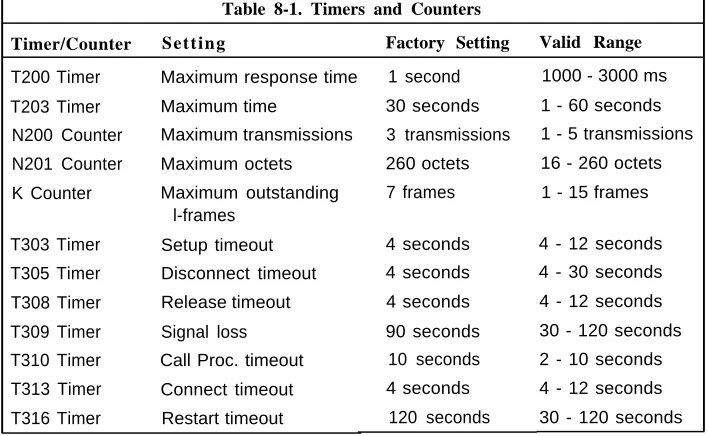
■ Timers and Counters
■ Terminal Equipment Identifier
■ Dial Plan Routing
■ Network Selection Tables
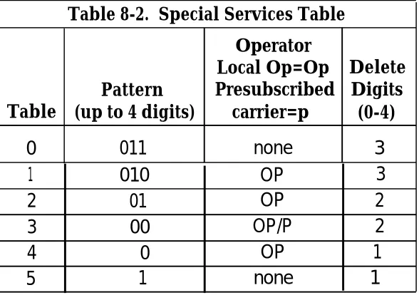
■ Special Services Tables
■ Call by Call Service Table
8-1 8-3 8-4 8-6 8-7 8-8 8-9 8-10 8-11 8-14 8-15 8-19 8-20 8-23
9
Telephones
■ Assign Trunks or Pools to Telephones
■ Copy Line/Trunk Assignments
■ Assign Intercom or System Access Buttons
9 - 1 9 - 2 9 - 6 9 - 8
Contents
Telephones
(continued)■ Analog Multiline Telephones without Built-in
Speakerphones 9-12
■ Analog Multiline Telephones with Voice Announce to
Busy 9-14
■ Analog Multiline Telephones with Simultaneous
Voice/Data 9-16
10
Auxiliary Equipment
10-1■ ■ ■ ■ ■ Music-on-Hold 10-1
Loudspeaker Paging 10-3
Fax 10-5
Maintenance Alarms 10-7
Voice Messaging System and Automated Attendant 10-8
11
Optional Telephone Features
■ ■ ■ ■ ■ ■ ■ ■ Extension Language Pool Dial-Out Code Call RestrictionsCopy Call Restrictions
ARS Restriction Level For Extensions Forced Account Code Entry
Microphone Operation Remote Call Forwarding
11-1 11-2 11-3 11-4 11-5 11-8 11-9 11-10 11-11
Contents
12
Optional Operator Features
12-1■ ■ ■ ■ ■ ■ ■ ■ ■ ■ ■ ■ ■ ■
Operator Hold Timer
DLC Operator Automatic Hold QCC Optional Features
Hold Return
Automatic Hold or Release Queue over Threshold Elevate Priority
Calls-In-Queue Alert
QCC Operator to Receive Call Types Call Type Queue Priority Level
Message Center Operation
Automatic or Manual Extended Call Completion Return Ring Interval
Position Busy Backup
12-2 12-3 12-4 12-5 12-6 12-7 12-8 12-9 12-10 12-12 12-14 12-15 12-16 12-17
13
Optional Telephone Features
■ ■ ■ ■ ■ ■ ■ ■ ■
Call Pickup Groups Group Paging
Group Coverage Member Assignments Group Coverage Delay Interval
Group Calling Member Assignments Group Calling Trunk or Pool Assignments Optional Group-Calling Features
Hunt Type
Group Calling Delay Announcement
13-1 13-2 13-3 13-4 13-6 13-7 13-9 13-10 13-11 13-12
Contents
Optional Group-Assigned Features
(continued)
■ Group Coverage Receiver 13-13
■ Group Calling Overflow and Threshold 13-14
■ Group Calling Message Waiting Indicator 13-16
■ Group Calling Calls-In-Queue Alarm Threshold 13-17
■ Group Calling External Alert for Calls-In-Queue Alarms 13-18
■ Group Type 13-19
14
System Features
■ ■ ■ ■ ■ ■ ■ ■ ■ ■ ■ ■ ■ ■ ■ ■ ■
Transfer Return Time
One-Touch Transfer/One-Touch Hold Transfer Audible
Type of Transfer
Camp-On Return Time Call Park Return Time Delay Ring Interval
Automatic Callback Interval Extension Status
SMDR Language
SMDR Call Report Format SMDR Call Length
SMDR Calls Recorded on Call Report Inside Dial Tone
Reminder Service Cancel
Redirect Outside Calls to Unassigned Extension Numbers Host System Dial Codes for Behind Switch Mode
14-1 14-3 14-4 14-6 14-7 14-8 14-9 14-10 14-11 14-12 14-13 14-14 14-15 14-16 14-17 14-18 14-19 14-21
Contents
System Features
(continued)■ ■ ■ ■ ■ ■ ■ ■ ■ ■ ■ Recall Timer AIlowed Lists
Assign Allowed Lists to Telephones Disallowed Lists
Assign Disallowed Lists to Telephones Remote Access Features
Remote Access Trunk Assignment Remote Access Automatic Callback Remote Access without Barrier Codes Remote Access Barrier Codes
Remote Access with Barrier Codes
14-22 14-23 14-24 14-25 14-26 14-27 14-29 14-30 14-31 14-34 14-35
15
Automatic Route Selection
■ 1 + 7 Digit Dialing Requirements■ ■ ■ ■ ■ ■ ■ ■ ■ ARS Tables
Start and Stop Times for Subpatterns Pool Routing
Facility Restriction Level Digit Absorption
Other Digits
N11 Special Numbers Tables Dial 0 Table
Voice and/or Data Routing
15-1 15-2 15-3 15-5 15-6 15-7 15-8 15-9 15-10 15-12 15-13
Contents
16
Night Service
■ Night Service with Group Assignment
■ Night Service with Outward Restriction
■ Night Service with Time Set
17
Labeling
16-1 16-2 16-4 16-6
Extension Directory Label Trunks
Posted Message Group Calling
System Speed Dial Directory
17-1 17-2 17-3 17-4 17-5 17-6
18
Print Reports
■ Report Language
■ Printing System Reports
19
Data Features
■ Analog Multiline Telephones with Simultaneous
Voice/Data
20
Integrated Administration
■ Capabilities18-1 18-2 18-3
19-1
19-3
20-1 20-1
Contents
A
Menu Hierarchy
A-1B
LED Displays
B-1C
General Feature Use and Telephone
Programming
C-1D
Button Diagrams
D-1E
Sample Reports
System Information Report Dial Plan Report
Label Information Report Tie Trunk Information Report DID Trunk Information Report GS/LS Trunk Information Report General Trunk Information Report DS1 Information Report
PRI Information Report
Remote Access (DISA) Information Report Operator Information Report
E-1 E-7 E-9 E-11 E-12 E-13 E-14 E-15 E-16 E-17 E-19 E-20
Contents
Sample Reports
(continued)Allowed Lists-Report
Access to Allowed Lists Report Disallowed Lists Report
Access to Disallowed Lists Report Automatic Route Selection Report Extension Directory Report
System Directory Report Group Paging Report
Extension Information Report
Group Coverage Information Report Direct Group Calling Information Report Night Service Information Report
Group Call Pickup Report Error Log Report
E-22 E-23 E-24 E-25 E-26 E-28 E-29 E-30 E-31 E-33 E-34 E-35 E-36 E-37
F
General System Programming Sequence
F-1G
Programming Special Characters
G - 1Contents
Figures
Introduction
Figure 1. MLX-20L Telephone 9
Figure 2. Console Overlay 11
Figure 3. System Busy Screen 17
A
Menu Hierarchy
Figure A-1. Menu Hierarchy A-1
D
Button Diagrams
Figure D-1. MLX Telephone Button Diagram (Hybrid/PBX
Mode) D-2
Figure D-2. Analog Multiline Telephone Button Diagram
(Hybrid/PBX Mode) D-3
Figure D-3. MLX Telephone Button Diagram (Key and
Behind Switch Mode) D-4
Figure D-4. Analog Multiline Telephone Button Diagram
(Key and Behind Switch Mode) D-5
Figures
Tables
Introduction
Table 1. Display Button Descriptions 10
Table 2. Programming Menu Options 15
3
System Operator Positions
Table 3-1. Maximum Number of Operator Positions 3-2
8
PRI Facilities
Table 8-1. Timers and Counters 8-13
Table 8-2. Special Services Table 8-20
19
Data Features
Table 19-1. Data Features: Programming Procedures 19-1
20
Integrated Administration
Table 20-1. Programming through Integrated
Administration 20-3
Table 20-2. Database Reconciliation Rules 20-4
B
LED Displays
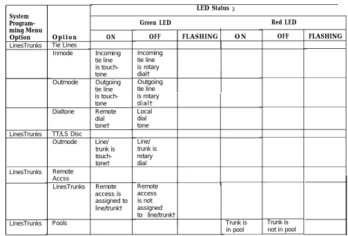
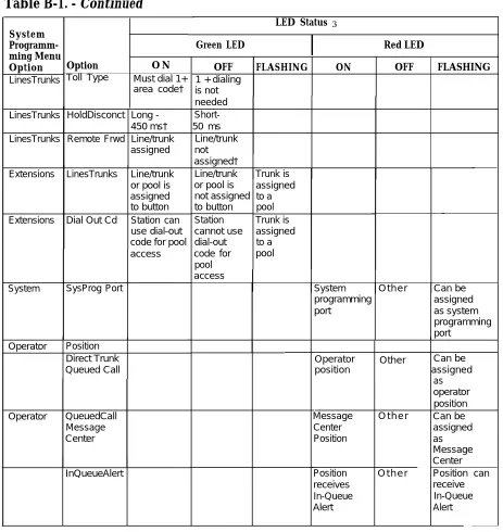
Table B-1. Line or Trunk Feature Status B-2
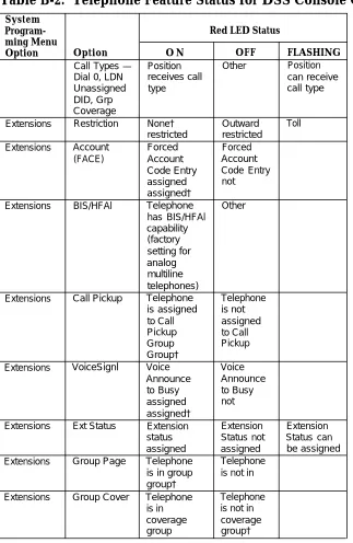
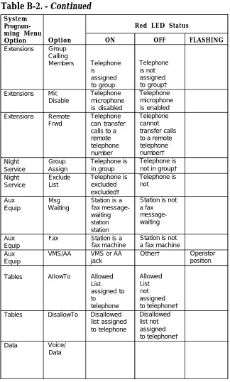
Table B-2. Telephone Feature Status for DSS Console
Only B-4
Tables
C
General Telephone Programming and
Feature Use
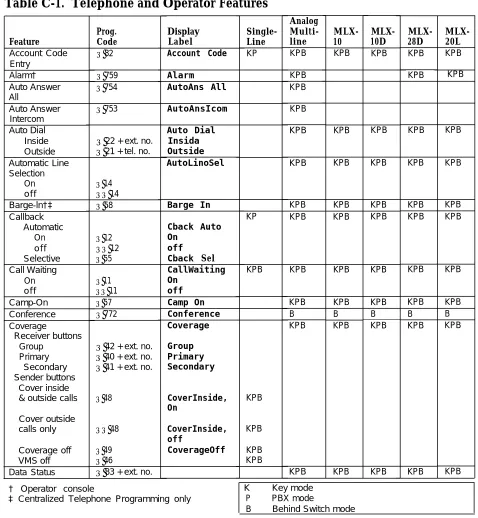
Table C-1. Telephone and Operator Features C-5 Table C-2. Programming Analog Multiline Telephones C-11 Table C-3. Programming MLX-10 Telephones C-12 Table C-4. Programming MLX Display Telephones Using
the Display C-13
E
Sample Reports
Table E-1. Report Contents E-1
Table E-2. System Reports E-3
G
Programming Special Characters
Table G-1. Table G-2.
Table G-3.
Table G-4.
Special Characters for Single-Line Telephones G-2
Special Characters for Analog Multiline
Telephones G-3
Special Characters for MLX Non-Display
Telephone G-4
Special Characters for MLX Display
Telephones G-5
CUSTOMER WARNING
This manual is designed for use by qualified service technicians
only. Technician qualification includes completion of an AT&T
hands-on instructor-led course covering installation and
maintenance for this product. Installation or maintenance of this product by anyone other than a qualified service technician may void the warranty. Hazardous electrical voltages are present
inside this product.
The exclamation point in an equilateral triangle is intended to alert the user to the presence of important operating and maintenance (servicing) instructions in the literature accompanying the product.
IMPORTANT SAFETY INSTRUCTIONS
When installing telephone equipment, always follow basic safety precautions to reduce the risk of fire, electrical shock, and injury to persons, including:
Read and understand all instructions.
Follow all warnings and instructions marked on or packed with the product.
Never install telephone wiring during a lightning storm.
Never install a telephone jack in a wet location unless the jack is specifically designed for wet locations.
Never touch uninsulated telephone wires or terminals unless the telephone wiring has been disconnected at the network interface
Use caution when installing or modifying telephone lines.
Use only AT&T-manufactured MERLIN LEGEND™ Communications System circuit modules, carrier assemblies, and power units in the MERLIN LEGEND Communications System (511A) control unit.
Use only AT&T-recommended/approved MERLIN LEGEND Communications System accessories.
If equipment connected to the analog station modules (008, 408, 408 GS/LS) or to the MLX telephone modules (008 MLX, 408 GS/LS-MLX) is to be used for in-range out-of-building (IROB) applications, IROB protectors are required.
Do not install this product near water, for example, in a wet basement location.
Do not overload wall outlets, as this can result in the risk of fire or electrical shock.
The MERLIN LEGEND Communications System is equipped with a three-wire grounding-type plug with a third (grounding) pin. This plug will fit only into a grounding-type power outlet. This is a safety feature. If you are unable to insert the plug into the outlet, contact an electrician to replace the obsolete outlet. Do not defeat the safety purpose of the grounding plug.
The MERLIN LEGEND Communications System requires a supplementary ground.
Do not attach the power supply cord to building surfaces. Do not allow anything to rest on the power cord. Do not locate this product where the cord will be abused by persons walking on it.
Slots and openings in the module housings are provided for ventilation. To protect this equipment from overheating, do not block these
openings.
Never push objects of any kind into this product through module openings or expansion slots, as they may touch dangerous voltage points or short out parts, which could result in a risk of fire or electrical shock. Never spill liquid of any kind on this product.
Unplug the product from the wall outlet before cleaning. Use a damp cloth for cleaning. Do not use cleaners or aerosol cleaners.
Customer Support Information
Support Telephone Number
In the U.S.A. only, AT&T provides a toll-free customer Helpline (1-800-628-2888)
24 hours a day. Call the Helpline, or your authorized dealer, if you need assistance when installing, programming, or using your system.
Outside the U.S.A., if you need assistance when installing, programming, or using
your system, contact your authorized AT&T dealer.
Federal Communications Commission (FCC) Electromagnetic Interference Information
This equipment has been tested and found to comply with the limits for a Class A digital device, pursuant to Part 15 of the FCC Rules. These limits are designed to provide reasonable protection against harmful interference when the equipment is operated in a commercial environment. This equipment generates, uses, and can radiate radio frequency energy and, if not installed and used in accordance with the instruction manual, may cause harmful interference to radio communications.
Operation of this equipment in a residential area is likely to cause harmful interference, in which case the user will be required to correct the interference at his own expense.
Canadian Department of Communications (DOC) Interference Information
This digital apparatus does not exceed the Class A limits for radio noise emissions set out in the radio interference regulations of the Canadian Department of
Communications.
Le Présent Appareil Numérique n’émet pas de bruits radioelectriques depassant Ies Iimites applicable aux appareils numériques de la class A prescribes clans Ie
reglernent sur Ie brouiilage radioelectrique edicté par Ie ministère des Communications du Canada.
Customer Support Information
FCC Notification and Repair Information
This equipment is registered with the FCC in accordance with Part 68 of its rules. In compliance with those rules, you are advised of the following:
■ Means of Connection. Connection of this equipment to the telephone network
shall be through a standard network interface jack: USOC RJ11C, RJ14C, RJ21X. Connection to E&M tie trunks requires a USOC RJ2GX. Connection to off-premises stations requires a USOC RJ11C or RJ14C. Connection to 1.544-Mbps digital facilities must be through a USOC RJ48C or RJ48X. Connection to DID requires a USOC RJ11C, RJ14C, or RJ21X. These USOCs must be ordered from your telephone company.
This equipment may not be used with party lines or coin telephone lines.
■ Notification to the Telephone Companies. Before connecting this
equipment, you or your equipment supplier must notify your local telephone company’s business office of the following:
The telephone number(s) you will be using with this equipment. — The appropriate registration number and ringer equivalence number
(REN), which can be found on the back or bottom of the control unit, as follows:
If this equipment is to be used as Key System, report the number AS593M-72914-KF-E.
If the system provides both manual and automatic selection of incoming/outgoing access to the network, report the number AS593M-72682-MF-E.
If there are no directly terminated trunks, or if the only directly terminated facilities are personal lines, report the number AS5USA-65646-PF-E.
The REN for all three systems is 1.5A.
— For tie line connection, the facility interface code (FIC) is TL31M and the service order code (SOC) is 9.0F.
For connection to off-premises stations, the FIC is OL13C and the SOC is 9.0F.
For equipment to be connected to 1.544-Mbps digital service, the FIC is 04DU9-B for D4 framing format or 04DU9-C for extended framing format, and the SOC is 6.0P.
For equipment to be connected to DID facilities, the FIC is 02RV2-T and the SOC is 9.0F.
— The quantities and USOC numbers of the jacks required.
— For each jack, the sequence in which lines are to be connected: the line types, the FIC, and the REN by position when applicable.
You must also notify your local telephone company if and when this equipment is permanently disconnected from the line(s).
The REN is used to determine the number of devices that maybe connected to the telephone line. Excessive RENs on the
x x
Customer Support InformationCustomer Support information
ringing in response to an incoming call. In most, but not all, areas the sum of the RENs should not exceed five (5.0). To be certain of the number of devices that may be connected to the line, as determined by the total RENs, contact the telephone company to determine the maximum REN for the calling area.
Installation and Operational Procedures
The manuals for your system contain information about installation and operational procedures.
Repair Instructions. If you experience trouble because your equipment is
malfunctioning, the FCC requires that the equipment not be used and that it be disconnected from the network until the problem has been corrected. Repairs to this equipment can be made only by the manufacturers, their authorized agents, or others who may be authorized by the FCC. In the event repairs are needed on this equipment, contact your authorized AT&T dealer or, in the
U.S.A. only, contact the National Service Assistance Center (NSAC) at
1-800-628-2888.
Rights of the Local Telephone Company. If this equipment causes harm to
the telephone network, the local telephone company may discontinue your service temporarily. If possible, they will notify you in advance. But if advance notice is not practical, you will be notified as soon as possible. You will also be informed of your right to file a complaint with the FCC.
Your local telephone company may make changes in its facilities, equipment, operations, or procedures that affect the proper functioning of this equipment. If they do, you will be notified in advance to give you an opportunity to maintain uninterrupted telephone service.
Hearing Aid Compatibility. The custom telephone sets for this system are
compatible with inductively coupled hearing aids as prescribed by the FCC.
Automatic Dialers. WHEN PROGRAMMING EMERGENCY NUMBERS AND/OR
MAKING TEST CALLS TO EMERGENCY NUMBERS:
Remain on the line and briefly explain to the dispatcher the reason for the call.
Perform such activities in off-peak hours, such as early morning or late evening.
Direct Inward Dialing (DID).
a. This equipment returns answer supervision signals to the Public Switched Telephone Network when:
(1) answered by the called station (2) answered by the attendant
(3) routed to a recorded announcement that can be administered by the customer premises equipment user
(4) routed to a dial prompt
Customer Support Information
DID calls forwarded Permissible
b. This equipment returns answer supervision on all back to the Public Switched Telephone Network. exceptions are when:
(1) a call is unanswered (2) a busy tone is received (3) a reorder tone is received
Allowing this equipment to be operated in such a manner as not to provide proper answer supervision signaling is in violation of Part 68 rules.
DOC Notification and Repair Information
NOTICE: The Canadian Department of Communications (DOC) label identifies certified
equipment. This certification means that the equipment meets certain
telecommunications network protective, operational, and safety requirements. The DOC does not guarantee the equipment will operate to the user’s satisfaction.
Before installing this equipment, users should ensure that it is permissible to connect it to the facilities of the local telecommunications company. The equipment must also be installed using an acceptable method of connection. In some cases, the company’s inside wiring for single-line individual service may be extended by means of a certified connector assembly (telephone extension cord). The customer should be aware that compliance with the above conditions may not prevent degradation of service in some situations.
Repairs to certified equipment should be made by an authorized Canadian
maintenance facility designated by the supplier. Any repairs or alterations made by the user to this equipment, or any equipment malfunctions, may give the
telecommunications company cause to request the user to disconnect the equipment. Users should ensure for their own protection that the electrical ground connections of the power utility, telephone lines, and internal metallic water pipe system, if present, are connected. This precaution may be particularly important in rural areas.
CAUTION: Users should not attempt to make such connections themselves, but should
contact the appropriate electrical inspection authority or electrician, as appropriate. To prevent overloading, the Load Number (LN) assigned to each terminal device denotes the percentage of the total load to be connected to a telephone loop used by the device. The termination on a loop may consist of any combination of devices subject only to the requirement that the total of the Load Numbers of all the devices does not exceed 100.
DOC Certification No.: 230 4095A CSA Certification No.: LR 56260 Load No.: 6
Customer Support Information
Renseignements sur la notification du ministère des Communications du Canada et la réparation
AVIS: L’étiquette du ministère des Communications du Canada identifie le materiel homologué. Cette étiquette certifie que le matériel est conforme à certaines normes de protection, d’exploitation et de sécurité des réseaux de télécommunications. Le
Ministère n’assure toutefois pas que le matériel fonctionnera à la satisfaction de l’utilisateur.
Avant d’installer ce matériel, l’utilisateur doit s’assurer qu’il est permis de le raccorder aux installations de l’entreprise locale de telecommunication. Le matériel doit
également être installé en suivant une méthode acceptée de raccordement. Dans certains cas, les fils intérieurs de l’enterprise utilises pour un service individual à ligne unique peuvent être prolongés au moyen d’un dispositif homologué de raccordement (cordon prolongateur téléphonique interne).
L’abonné ne doit pas oublier qu’il est possible que la conformity aux conditions énoncées ci-dessus n’empêchent pas la degradation du service dans certaines
situations. Actuellement, les entreprises de telecommunication ne permettent pas que l’on raccorde leur matériel à des jacks d’abonné, sauf clans les cas précis prévus pas les tarifs particuliers de ces entreprises.
Les réparations de matériel homologué doivent être effectuées par un centre d’entretien canadien autorisé désigné par le fournisseur. La compagnie de
telecommunications peut demander à l’utilisateur de débrancher un appareil à la suite de reparations ou de modifications effectuées par l’utilisateur ou à cause de mauvais fonctionnement.
Pour sa propre protection, l’utilisateur doit s’assurer que tous les fils de mise à la terre de la source d’énergie électrique, des lignes téléphoniques et des canalisations d’eau métalliques, s’il y en a, sent raccordés ensemble. Cette précaution est
particulièrement importance dans les régions rurales.
AVERTISSEMENT: L’utilisateur ne doit pas tenter de faire ces raccordements
lui-même; il doit avoir recours à un service d’inspection des installations électriques, ou à un electrician, selon le cas.
L’indite de charge (IC) assigné à chaque dispositif terminal indique, pour éviter toute surcharge, le pourcentage de la charge totale qui peut être raccordée à un circuit téléphonique bouclé utilisé par ce dispositif. La terminaison du circuit bouclé peut être constitute de n’importe quelle combinaison de dispositifs, pourvu que la somme des indices de charge de l’ensemble des dispositifs ne dépasse pas 100.
No d’homologation: 230 4095A No de certification: CSA LR 56260
L’indice de charge: 6
Customer Support Information
MERLIN LEGEND D.O.C. Location Label Placement
Ministère des Communications du Canada emplacement de l’étiquette
Customer Support Information
Security of Your System-Preventing Toll Fraud
As a customer of a new telephone system, you should be aware that there exists an increasing problem of telephone toll fraud. Telephone toll fraud can occur in many forms, despite the numerous efforts of telephone companies and telephone equipment manufacturers to control it. Some individuals use electronic devices to prevent or falsify records of these calls. Others charge calls to someone else’s number by illegally using lost or stolen calling cards, billing innocent parties, clipping on to
someone else’s line, and breaking into someone else’s telephone equipment physically or electronically. In certain instances, unauthorized individuals make connections to the telephone network through the use of remote access features.
The Remote Access feature of your system, if you choose to use it, permits off-premises callers to access the system from a remote telephone by using an 800 number or a 7- or 10-digit telephone number. The system returns an
acknowledgement signaling the user to key in his or her authorization code, which is selected and administered by the system manager. After the authorization code is accepted, the system returns dial tone to the user. If you do not program specific egress restrictions, the user will be able to place any call normally dialed from a telephone associated with the system. Such an off-premises network call is originated at, and will be billed from the system location.
The Remote Access feature, as designed, helps the customer, through proper administration, to minimize the ability of unauthorized persons to gain access to the network. Most commonly, phone numbers and codes are compromised when overheard in a public location, through theft of a wallet or purse containing access information, or through carelessness (writing codes on a piece of paper and improperly discarding it). Additionally, hackers may use a computer to dial an access code and then publish the information to other hackers. Enormous charges can be run up quickly. It is the customer’s responsibility to take the appropriate steps to properly implement the features, evaluate and administer the various restriction levels, protect access codes, and distribute access codes only to individuals who have been fully advised of the sensitive nature of the access information.
Common carriers are required by law to collect their tariffed charges. While these charges are fraudulent charges made by persons with criminal intent, applicable tariffs state that the customer of record is responsible for payment of all long-distance or other network charges. AT&T cannot be responsible for such charges and will not make any allowance or give any credit for charges that result from unauthorized access.
Customer Support Information
To minimize the risk of unauthorized access to your communications system:
■ ■ ■ ■ ■ ■ ■ ■ ■
Use a nonpublished Remote Access number.
Assign authorization codes randomly to users on a need-to-have basis,
keeping a log of ALL authorized users and assigning one code to one person. Use random sequence authorization codes, which are less likely to be easily broken.
Deactivate all unassigned codes promptly.
Ensure that Remote Access users are aware of their responsibility to keep the telephone number and any authorization codes secure.
When possible, restrict the off-network capability of off-premises callers, via use of Call Restrictions and Disallowed List capabilities.
When possible, block out-of-hours calling.
Frequently monitor system call detail reports for quicker detection of any unauthorized or abnormal calling patterns.
Limit Remote Call Forward to persons on a need-to-have basis.
Limited Warranty and Limitation of Liability
AT&T warrants to you, the customer, that your MERLIN LEGEND Communications System will be in good working order on the date AT&T or its authorized reseller delivers or installs the system, whichever is later (“Warranty Date”). If you notify AT&T or its authorized reseller within one year of the Warranty Date that your system is not in good working order, AT&T will without charge to you repair or replace, at its option, the system components that are not in good working order. Repair or replacement parts may be new or refurbished and will be provided on an exchange basis. If AT&T determines that your system cannot be repaired or replaced, AT&T will remove the system and, at your option, refund the purchase price of your system, or apply the purchase price towards the purchase of another AT&T system.
If you purchased your system directly from AT&T, AT&T will perform warranty repair in accordance with the terms and conditions of the specific type of AT&T maintenance coverage you selected. If you purchased your system from an AT&T-authorized
reseller, contact your reseller for the details of the maintenance plan applicable to your system.
This AT&T limited warranty covers damage to the system caused by power surges, including power surges due to lightning.
The following will not be deemed to impair the good working order of the system, and AT&T will not be responsible under the limited warranty for damages resulting from
Customer Support Information
■ failure to follow AT&T’s installation, operation, or maintenance instructions
■ unauthorized system modification, movement, or alteration
■ unauthorized use of common carrier communication services accessed through the system
■ abuse, misuse, or negligent acts or omissions of the customer and persons under the customer’s control
■ acts of third parties and acts of God
AT&T’S OBLIGATION TO REPAIR, REPLACE, OR REFUND AS SET FORTH ABOVE IS YOUR EXCLUSIVE REMEDY.
EXCEPT AS SPECIFICALLY SET FORTH ABOVE, AT&T, ITS AFFILIATES, SUPPLIERS, AND AUTHORIZED RESELLERS MAKE NO WARRANTIES, EXPRESS OR IMPLIED, AND SPECIFICALLY DISCLAIM ANY WARRANTIES OF MERCHANTABILITY OR FITNESS FOR A PARTICULAR PURPOSE.
Limitation of Liability
EXCEPT FOR PERSONAL INJURY, DIRECT DAMAGES TO TANGIBLE PERSONAL PROPERTY PROXIMATELY CAUSED BY AT&T, AND LIABILITY OTHERWISE EXPRESSLY ASSUMED IN A WRITTEN AGREEMENT SIGNED BY AT&T, THE
LIABILllY OF AT&T, ITS AFFILIATES, SUPPLIERS, AND AUTHORIZED RESELLERS FOR ANY CLAlMS, LOSSES, DAMAGES, OR EXPENSES FROM ANY CAUSE
WHATSOEVER (INCLUDING ACTS OR OMISSIONS OF THIRD PARTIES),
REGARDLESS OF THE FORM OF ACTION, WHETHER IN CONTRACT, TORT OR OTHERWISE, SHALL NOT EXCEED AN AMOUNT EQUAL TO THE LESSER OF THE DIRECT DAMAGES PROVEN OR THE PURCHASE PRICE OF THE SYSTEM. IN NO EVENT SHALL AT&T OR ITS AFFILIATES, SUPPLIERS, OR AUTHORIZED RESELLERS BE LIABLE FOR INCIDENTAL, RELIANCE, CONSEQUENTLY, OR ANY OTHER
INDIRECT LOSS OR DAMAGE (INCLUDING LOST PROFITS OR REVENUES)
INCURRED IN CONNECTION WITH THE SYSTEM. THIS LIMITATION OF LIABILITY SHALL SURVIVE FAILURE OF THE EXCLUSIVE REMEDY SET FORTH IN THE LIMITED WARRANTY ABOVE.
Voice Mail Systems
Your Voice Mail system permits callers to leave verbal messages for system users or gain access to the back-up position in an emergency as well as create and distribute voice messages among system users.
The Voice Mail system, through proper administration, can help you reduce the risk of unauthorized persons gaining access to the network. However, phone numbers and authorization codes can be compromised when overheard in a public location, are lost through theft of a wallet or purse containing access information, or through
Customer Support Information
carelessness (writing codes on a piece of paper and improperly discarding them). Additionally, hackers may use a computer to dial an access code and then publish the information to other hackers. Substantial charges can accumulate quickly. It is your responsibility to take appropriate steps to implement the features properly, evaluate and administer the various restriction levels, protect and carefully distribute access codes.
Under applicable tariffs, you will be responsible for payment of toll charges. AT&T cannot be responsible for such charges and will not make any allowance or give any credit resulting from unauthorized access.
To reduce the risk of unauthorized access through your Voice Mail system, please observe the following procedures:
Employees who have voice mailboxes should be required to use the passwords to protect their mailboxes.
— Have them use random sequence passwords.
— Impress upon them the importance of keeping their passwords a secret.
— Encourage them to change their passwords regularly.
The administrator should remove any unneeded voice mailboxes from the system immediately.
AUDIX Voice Power™ has the ability to limit transfers to subscribers only. You are strongly urged to limit transfers in this manner.
Use the PBX or Key system administration capability to do the following: — Block direct access to outgoing lines and force the use of account
codes/authorization codes.
— Disallow trunk-to-trunk transfer unless required.
— Assign toll restriction levels to all AUDIX Voice Power ports.
— If you do not need to use the Outcalling feature, completely restrict the outward calling capability of the AUDIX Voice Power ports.
Monitor SMDR reports or Call Accounting System reports for outgoing calls that might be originated by AUDIX Voice Power ports.
Remote Administration and Maintenance
The Remote Administration and Maintenance feature of your telecommunications system, if you choose to use it, permits users to change the system features and capabilities from a remote location.
The Remote Administration and Maintenance feature, through proper administration, can help you reduce the risk of unauthorized persons gaining access to the network. However, telephone numbers and authorization codes can be compromised when
Customer Support Information
or purse containing a piece of paper and computer to dial an overheard in a public location, are lost through theft of a wallet
access information, or through carelessness (writing codes on improperly discarding them). Additionally, hackers may use a
access code and then publish the information to other hackers. Substantial charges can accumulate quickly. It is your responsibility to take appropriate steps to implement the features properly, evaluate and administer the various restriction levels, and protect and carefully distribute access codes.
Under applicable tariffs, you will be responsible for payment of toll charges. AT&T cannot be responsible for such charges and will not make any allowance or give any credit resulting from unauthorized access.
To reduce the risk of unauthorized access through Remote Administration and Maintenance, please observe the following procedures:
■ The System Administration and Maintenance capability of a PBX or Key system is protected by a password.
— Change the default password immediately. — Continue to change the password regularly.
— Only give the password to people who need it and impress upon them the need to keep it secret.
— If anyone who knows the password leaves the company, change the password immediately.
■ If you have a special telephone line connected to your PBX or Key system for Remote Administration and Maintenance, you should do one of the following:
Unplug the line when it is not being used.
Install a switch in the line to turn it off when it is not being used.
Keep the Remote Administration and Maintenance telephone number secret. Only give it to people who need to know it, and impress upon them the need to keep it a secret. Do not write the telephone number on the PBX or Key system, the connecting equipment, or anywhere else in the system room.
■ If your Remote Administration and Maintenance feature requires that someone in your office transfer the caller to the Remote Administration and Maintenance extension, you should impress upon your employees the importance of only transferring authorized individuals to that extension.
About This Book
This book, which provides summaries of each procedure for programming the MERLIN LEGEND™ Communications System, is intended for qualified service personnel and technicians. The material is presented in the order in which you would program a new system. Additional information is available as follows:
More detailed procedures for system programming, along with information on how to program on the system programming console and on the PC, can be found in System Programming.
Complete instructions on using SPM can be found in System
Programming and Maintenance (SPM).
Detailed information about all of the features described here can be found in the Feature Reference.
Detailed information on how to choose among the many options provided for each feature can be found in System Planning.
About This Book
Conventions
The following typographical conventions are used in this book:
■ Bold type is used for telephone buttons.
Press Drop to delete the current entry.
Italic type is used for substitutable values for which you must supply a
■
specific value.
Specify extension: dial/type [nnnn]. Specify slot and port: dial/type [sspp].
■ Constant width type is used for information on telephone display screens or on a PC screen.
Select Sys Program.
■ Bold constant width type indicates information that you enter exactly as shown.
Dial #55.
■ Keys on the PC are shown in boxes.
Press [F7] .
■ When two keys are to be pressed at the same time, the keys are connected by a plus sign.
Press [Alt] + [P] .
■ The Enter (Return) key on a PC is shown as
↵ .
About This Book
Product Safety Labels
Throughout this book, point inside a triangle
hazardous along with
situations are indicated by an exclamation the word warning or caution.
WARNING:
Warning indicates the presence of a hazard that could cause death or severe personal injury if the hazard is not avoided.
CAUTION:
Caution indicates the presence of a hazard minor personal jnjury or property damage if avoided.
that will or can cause the hazard is not
About This Book
Related Documents
Document No. 555-620-114 555-620-110 555-620-115 555-620-116 555-620-111 555-620-112 555-620-113 555-620-122 555-620-123 555-620-150 555-620-152 555-620-124 555-620-125 555-620-151 555-620-120 555-620-121 555-620-128 555-620-126 555-620-127 555-620-134 555-620-135 555-620-132 555-620-133 555-620-136 555-620-137 Title System Documents System Overview Feature ReferenceEquipment and Operations Reference Pocket Reference
System Programming System Planning
System Planning Forms
Telephone User Support
MLX-10D™, MLX-28D™, and MLX-20L™ Display Telephones User’s Guide
MLX-10D™, MLX-28D™, and MLX-20L™ Display Telephones Quick Reference
MLX-10D™ Telephone Tray Cards (6 cards)
MLX-28D™ and MLX-20L™ Telephone Tray Cards (5 cards)
MLX-10™ Non-Display Telephone User’s Guide
MLX-10™ Non-Display Telephone Quick Reference
MLX-10™ (non-display) Telephone Tray Cards (6 cards)
Analog Multiline Telephones User’s Guide
Analog Multiline Telephones Quick Reference MLC-5 Cordless Telephone Quick Reference Single-Line Telephones User’s Guide
Single-Line Telephones Quick Reference
System Operator Support
MLX Direct-Line Consoles Operator’s Guide MLX Direct-Line Consoles Quick Reference Analog Direct-Line Consoles Operator’s Guide
Analog Direct-Line Consoles Quick Reference MLX Queued Call Console Operator’s Guide
MLX Queued Call Console Quick Reference
About This Book
Document No. Title
555-620-130 555-620-131 555-620-129
555-620-140
555-620-141 555-620-142 555-620-143 555-620-144
Miscellaneous User Support
Calling Group Supervisor’s Guide
Calling Group Supervisor’s Quick Reference Data User’s Guide
Documentation for Qualified Technicians
Installation, Programming, & Maintenance (IP&M) Binder
(consists of 555-620-141,555-620-142, 555-620-143, and 555-620-1 44)
Installation
System Programming & Maintenance (SPM) Maintenance and Troubleshooting
Programming Summary
About This Book
How to Comment on This Document
We welcome your comments, both positive and negative. Please use the feedback form on the next page to let us know how we can continue to serve you. If the feedback form is missing, write directly to
A. Sherwood AT&T
99 Jefferson Road Room 2A25
Parsippany, NJ 07054
Introduction
This chapter covers the information you need to know before you begin system programming.
It describes the following:
system programming console, buttons, and overlay
types of programming
programming summary contents
programming basics
programming menu options
idle states
Introduction
System Programming Console
The system programming console is an MLX-20L telephone connected to the system programming jack. When you enter system programming on a new system for the first time, the console must be connected to the first jack on the first 008 MLX module or 408 GS/LS-MLX module (Release 2.0 and later
versions). This jack is factory set as the system programming jack and as an operator position. After you enter programming, you can change the system programming jack to any one of the first five jacks on the first 008 MLX
module or 408 GS/LS-MLX module (Release 2.0 and later versions). This allows you to program without interfering with the operator’s call handling.
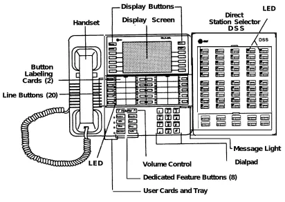
You can also have one or two Direct Station Selectors (DSSs) connected to the system programming console. Each DSS adds 50 extension buttons to the console, which facilitates assigning features to telephones.
The MLX-20L telephone with a DSS is shown in Figure 1.
Introduction
Display Buttons Display Screen
D S S
Line Buttons (20) Button Labeling Cards (2)
Handset
LED Direct
Station Selector
LED
I
Message Volume Control Dialpad Dedicated Feature Buttons (8) User Cards and TrayLight
Figure 1. MLX-20L Telephone
Introduction
Console Buttons
System programming can be done using the console’s 14 display-area buttons. These buttons are arranged in two columns of seven buttons. The top two buttons in each column
regardless of the display. Table
have the same labels and functions 1 describes these functions.
Table 1. Display Button Descriptions
Button Function
H o m e Return to normal call-handling mode after you finish programming. This button displays the Home screen.
M e n u Display the Main Menu shown in Figure 1-2.
More Display more menu items when a menu is continued on more than one screen (indicated by a “>”).
Inspct (Inspect) View a list of lines or telephones on which a feature is programmed.
Introduction
Console Overlay
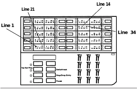
The programmable lines and buttons are on the main part of the console. There are 20 physical buttons on the console itself but you can use the
overlay to program up to 34 lines. Some of the unlabeled buttons on the lower part of the console may also be used for programming features. You can also use the dialpad for entering feature and programming codes.
Figure 2 illustrates the system console overlay.
Line 14
Line 21Line 1
❑ ❑ ❑
❑ ❑ ❑
❑ ❑ ❑
❑ ❑ ❑
Line 34
Figure 2. Console Overlay
Appendix D shows the button diagrams for the telephones used in the communications system. Refer to this appendix when programming buttons for other telephones.
Introduction
Programming Information
This section covers basic system programming information. See System
Programming for more information.
Types of Programming
There are three types of programming for the communications system:
System Programming — enables the System manager to program
features that affect all or most system users. System programming requires one the following:
— an MLX-20L™ telephone connected to one of the first five ports of the first MLX module in the control unit
— a PC with System Programming and Maintenance (SPM)
software connected to the lower RS-232 port on the processor, with a built-in modem in the processor. The modem permits remote programming and maintenance via the public network. SPM emulates a system programming console on your PC.
NOTE:
If your system has the AT&T Integrated Solution II (IS II)—UNIX® application, you have a Master Controller equipped with the UNIX version of SPM. See Chapter 2 in System Programming for more information.
Extension Programming enables individual telephone users and
system operators (except for QCC operators) to change their
telephone features to meet individual needs. For details on extension programming, see the appropriate user and operator guides.
Centralized Telephone Programming enables the System manager
to program any feature that can be programmed by individual telephone users or system operators. Centralized Telephone
Programming can be done on the programming console or on a PC with the SPM software. For details on Centralized Telephone
Programming, see Chapter 4 in System Programming.
Introduction
Programming Summary Contents
Each programming summary contains a general description of the feature and provides the folIowing programming information:
Programmable by—indicates who has system permission to use the procedure
Mode—specifies which system mode supports the procedure
Idle condition—specifies the idle state required before the procedure can be performed
Planning form —indicates which planning forms provide information for the procedure
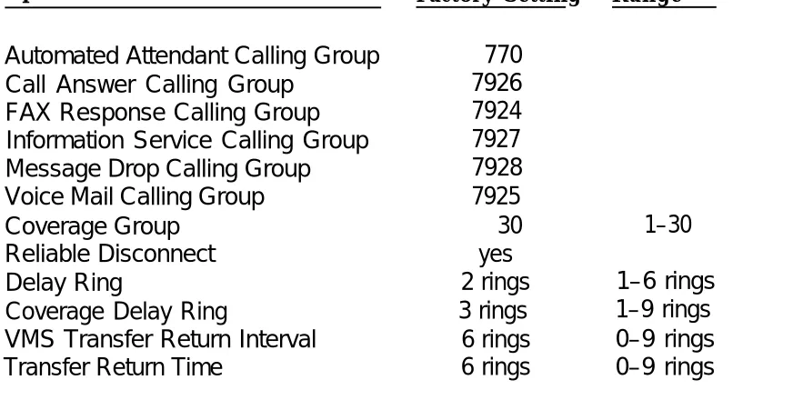
Factory setting—shows the default settings, if any, for equipment or features affected by the procedure
Valid entries—specifies the characters or numbers accepted during data entry
Inspect—specifies whether or not the feature status can be verified using the Inspect feature
Copy option—indicates whether or not the feature programmed with procedure can be copied to another system component
Console Procedure—provides a summary of the procedure steps if using the system console
PC Procedure—provides a summary of the procedure steps if using SPM
Introduction
Programming Basics
To begin programming, do the following:
On the console:
On the PC:
In most cases, to exit
Select Menu → Sys Program → Exit: The System Programming menu is displayed.
Type SPM → [↵] → Press any key → [F1] → [F5] : The System Programming menu is displayed.
from a screen without making any changes, press Exit or [F5] . Exceptions are noted as part of a procedure.
Ordinarily you complete a procedure by pressing Enter ( [F10] ) to save the information you have programmed. occasionally you press Exit ( [F5] ) and go back to the previous screen.
If you are programming a group of sequentially numbered extensions or trunks, you may have the option of pressing Next ( [F8] ) to save your entry
and automatically provide the number of the next extension or trunk in the
sequence, thus saving you a couple of steps.
When you have completed a procedure, pressing Exit ( [F5] ) takes you Up one screen in the menu hierarchy.
In most cases, you will be at an intermediate step in the procedure you have
just completed. At that point, you can select one of the options shown on the screen and continue programming, or you can press Exit again. This
usually takes you back to the System Programming menu. If not, you again have the option of continuing to program from the current screen or pressing Exit again.
In a few cases, pressing Exit brings you back to the System Programming menu where you can select another option to program or exit from system programming.
Introduction
Programming Menu Options
Table 2 lists the options that display on the System Programming menu.
Table 2. Programming Menu Options
Option Description System
SysRenumber
Operator
LinesTrunks
Extensions
Opt ions
Tables
AuxEquip
NightSrvce
Labeling
Set system operating conditions.
Select the system numbering plan and/or reassign extension numbers with 1- to 4-digit numbers that are more appropriate or convenient for your company.
Assign or remove operator positions and program operator features (such as Operator Hold Timer or QCC options).
Program line/trunk options.
Program features for telephones (such as restrictions, line assignments).
Program system-wide features (such as Transfer Return, Delay Ring).
Program features (such as Allowed
Program auxiliary
that require entering information in a table Lists, Disallowed Lists).
equipment connected to the system (such as loudspeaker paging, fax).
Program Night Service features.
Program the labels shown on display telephones (such as System Directory, Posted Messages).
Continued on next page
Introduction
Table 2.- Continued
Option Description
Data Specify telephones that need simultaneous voice and data capability.
Print Print system programming reports (such as system configuration, extension assignments).
Cntrl Prog Do centralized telephone programming (assign features to specific buttons on telephones).
Language Select the language that your console uses to display text on the screens. Selections are English (default), French, and Spanish.
Exit Exit system programming.
Introduction
Idle States
Some programming procedures can be started only when the entire system, or some part of the system (such as a trunk or an extension), is idle, that is, not in use. Some procedures require that a trunk or extension be idle only at the instant of programming. Lengthy procedures require the system, trunk, or extension be forced into remaining idle until programming is completed.
These procedures wait for the system or trunk or extension to become idle and then prevent the initiation of any new calls—a condition called forced idle.
If a procedure requires an normal business hours.
If a procedure requires an begin, you see the screen
idle condition, do the programming outside of
idle system and the system is busy when you shown in Figure 3.
System Busy Pls Wait
Dial Code: nnnn Slot/Port: ss/pp
Exit
Figure 3. System Busy Screen
When the system is no longer busy, the screen changes to the appropriate programming screen.
Introduction
System Forced Idle
When the entire system is forced idle, no calls can be made or received. The following procedures can be done only when the entire system (all lines and telephones) is idle:
■ ■ ■ ■ ■
■ ■ ■
select system mode
identify system operator positions renumber system
renumber modules
identify telephones with voice signal pairs for Voice Announce to Busy feature
identify telephones needing Simultaneous Voice and Data feature restore system programming information
identify Music-on-Hold jack
When the system is forced idle, all multiline telephone users hear a signal, indicating that the telephone cannot be used. On a display telephone, the message
Wait: System Busy
appears. Single-line telephones do not get a dial tone.
Line or Trunk Idle
The following procedures can be done only when the line or trunk being
programmed is idle. Since these procedure require the line or trunk to be idle only at the instant of programming, the line or trunk is not forced idle as
described above.
■ identify loudspeaker paging line jack
■ assign trunks to pools
■ specify incoming or outgoing DID or tie-trunk type ■ specify tie-trunk direction
■ specify tie-trunk E&M signal
Introduction
Extension Forced Idle
When a telephone or data terminal is forced idle, no calls can be made or received on that telephone or data terminal, The following procedures can be started only when the telephone or data terminal being programmed is idle.
■ assign call restrictions
■ assign pool dial-out restrictions
■ copy telephone assignments
■ assign lines, trunks, or pools to extensions
■ assign labels to a Personal Directory
■ use centralized telephone programming
When the telephone is forced idle, a multiline telephone user hears a signal, indicating that the telephone cannot be used. On a display telephone, the message
Wait: System Busy
appears. Single-line telephone user does not get a dial tone.
100D Module Idle
The following can be done only when the 100D Module is idle:
■ specify board type
■ specify frame format
■ specify board signaling format ■ specify board suppression format
■ specify board facility compensation
Introduction
Forced Idle Reminder Tones
Forced idle reminder tones are provided in the following situations:
■ At the telephone, to remind an extension that the system or the extension is in the forced idle state.
■ At the programming console or SPM, to remind the system manager that the system or at least one extension is in the forced idle state because of administrative activity.
This tone is a high-low “doorphone” tone (400 ms of 667 Hz tone followed by 400 ms of 571 Hz tone).
In a Release 1.1 or Release 2.0 system, all three tones occur every 20 seconds. You can adjust the volume of these tones with the volume control.
Basic System Operating
Conditions
1
The procedures in this chapter are all related to the system rather than to the operation of telephones, operator positions, or trunks. These are conditions that have to be set only when the system is new or, sometimes, after a frigid start.
NOTE:
You have to reset the system time when Daylight Savings Time begins and ends.
This chapter contains the following programming procedures:
System Restart
System Programming Position Assignment
Mode of Operation
Board Renumbering
Automatic Maintenance Busy
System Date
System Time
System Language
Basic System Operating Conditions
System Restart
Use
CAUTION:
This procedure is for qualified support personnel only.
this procedure to perform a system restart (cold start).
All calls are dropped when you perform this procedure. System programming is saved.
Telephones with the Extension Status feature can lose toll restrictions as a result of a cold start.
Summary: System Restart
Programmable by Qualified support personnel
Mode All
Idle Condition Not required
Planning Form Not applicable
Factory Setting None
Valid Entries None
Inspect No
Copy Option No
Console Procedure System → Restart → Yes PC Procedure [ F 1 ] → [ F 1 ] → [ F 1 ]
Basic System Operating Conditions
System Programming Position
Assignment
Use this procedure to reassign the station jack used for system programming. This jack should not be the same jack used for the operator position.
The system programming position can be reassigned only to one of the first five jacks on the first MLX module. Only one system programming console is allowed per system.
If you are programming on the console:
■ The console must be connected to the station jack currently assigned
for system programming.
■ As soon as you change the system programming jack, the system programming session is terminated. To proceed with system
programming, you must connect the system programming console to the newly assigned station jack and re-enter system programming.
Basic System Operating Conditions
Summary: Assign System Programming
Position
Programmable by
Mode
Idle Condition
Planning Form,
Factory Setting
Valid Entries
Inspect
Copy Option
Console Procedure
PC Procedure
System manager
All
Not required
Form 1, System Planning
First jack on first MLX module (also set as an operator position)
Extension number of one of the first five jacks on the first MLX module
No
No
System → SProg Port → Drop → Dial ext. no. → Enter → Exit
[F1] → [F2] → [Alt] + [P] → Type ext. no. → [F10] → [F5]
Basic System Operating Conditions
System Language
Release 1.1 and 2.0 Only
Your communications system offers you a choice of three languages (English, French, and Spanish) for the following options:
■ System language (set first)
■ Station Message Detail Recording (SMDR) reports (see “System Features”)
■ Print reports (see “Printing Reports”)
■ Extensions (see “Optional Telephone Features”)
Use this procedure to set the system language.
Summary: System Language
Programmable by
Mode
Idle Condition
Planning Form
Factory Setting
Valid Entries
Inspect
Copy Option
Console Procedure
PC Procedure
System manager
All
Not required
Form 1, System Planning
English
English, French, Spanish
No
No
More → Language → SystemLang → Yes → Select a language → Enter
[PgUp] → [F6] language → [F10]
→ [F1] → [F3] → Select a
Basic System Operating Conditions
Board Renumbering
Use
CAUTION:
This procedure is to be performed by qualified support personnel only.
this procedure to renumber boards that have already been installed. Note that this is not the same procedure as the Boards option, available to qualified service personnel with SPM only. This procedure restarts the system (system programming is not lost).
Summary: Board Renumbering
Programmable by
Mode
Idle Condition
Planning Form
Factory Setting
Valid Entries
Inspect
Copy Option
Console Procedure
PC Procedure
Qualified support personnel only
All
System idle
Not app
None
Not app
licable
licable
Not applicable
Not applicable
System → Board Renum → Yes [F1] → [F4] → [F2]
Basic System Operating Conditions
Mode of Operation
The system mode-Key, Behind Switch, or Hybrid/PBX-determines how the system operates. More specifically, the system mode determines:
■ how lines or trunks are provided to users
■ types of operator consoles allowed
■ features available
Changing this option causes a system restart and terminates the
programming session. You must re-enter system programming to program other features.
NOTE:
The Hybrid/PBX option is not available if the control unit processor module has been modified with the hardware strap in place to operate in Key mode only. See Equipment and Operations Reference.
These
■
■
■
■
■
■
■
options cannot be programmed for Key or Behind Switch systems:
Automatic Route Selection (ARS)
Pools
Queued Call Consoles (QCCs) and associated features
Direct Inward Dialing (DID) Trunks
System Access buttons
Dial Plan Routing (PRI)
Call by Call Services (PRI)
The Ground-start trunks option cannot be programmed if the processor module has been modified for Key mode-only operation.
Basic System Operating Conditions
Summary: Mode of Operation
Programmable by
Mode
Idle Condition
Planning Form
Factory Setting
Valid Entries
Inspect
Copy Option
Console Procedure
PC Procedure
System manager
All
System idle
Form 1, System Planning
Key
Key, Behind Switch, Hybrid/PBX
No
No
System → Mode → Select mode → Enter [F1] → [F3] → Select mode → [F10]
Basic System Operating Conditions
Automatic Maintenance Busy
Automatic Maintenance Busy allows the system to take a malfunctioning trunk out of service for outgoing calls. (Incoming calls are never blocked.) This
protects against disruptions in outgoing calling patterns that are caused by faulty outside facilities.
For optimum performance, enable Automatic Maintenance Busy for Hybrid/PBX systems with pooled trunks.
NOTE:
No more than 50% of the trunks in a trunk pool are allowed to be placed in the maintenance-busy state at one time unless the central office has failed to disconnect a trunk (which prevents anyone from using that trunk) or an entire trunk module is manually taken out of use (a user-imposed maintenance-busy state).
Basic System Operating Conditions
Summary: Automatic Maintenance Busy
Programmable by System manager
Mode All
Idle Condition Not required
Planning Form Form 1, System Planning
Factory Setting Disabled
Valid Entries Enabled, Disabled
Inspect No
Copy Option No
Console Procedure To disable Automatic Maintenance Busy:
System → MaintenBusy → Disable → Enter
→ Exit
To enable Automatic Maintenance Busy – no tie trunks:
System → MaintenBusy → Enable → Enter
→ Exit
To enable/disable with tie trunks:
System → MaintenBusy → Enable → Enter → Enable/Disable → Enter → Exit
PC Procedure To disable Automatic Maintenance Busy: [F1] → [F6] → [F2] → [F10] → [F5]
To enable Automatic Maintenance Busy -no tie trunks:
[F1] → [F6] → [F1] → [F10] → [F5] To enable/disable with tie trunks:
[F1] → [F6] → [F1] → [F10] → [F1] / [F2] → [F10] → [F5]
Basic System Operating Conditions
System Date
The System Date feature allows you to set the month, day, and year that appear on MLX display telephones and on Station Message Detail Recording (SMDR) reports.
NOTE:
If you are planning to use the SMDR feature, make sure the current date is set.
Summary: Set System Date
Programmable by
Mode
Idle Condition
Planning Form
Factory Setting
Valid Entries
Inspect
Copy Option
Console Procedure
PC Procedure
System manager
All
Not required
Form 1, System
01-01-00
Month: 01-12 Day: 01-31 Year: 00-99
No
No
Planning
System → Date → Drop → Dial current date → Enter → Exit
[F1] → [F7] → [Alt] + [P] → Type current date → [F10] → [F5]
Basic System Operating Conditions
System Time
The System Time feature allows you to set the time that appears on MLX display telephones and on SMDR reports.
NOTE:
If you are planning to use the SMDR feature, make sure the system time is set accurately.
If you change the system time while the system is in Night Service mode, Night Service is deactivated and must be manually reactivated.
If you have installed applications such as Call Management System (CMS) or AUDIX™ Voice Power, you may need to set the time in the applications
software whenever you reset the system time.
Summary: Set System Time
Programmable by
Mode
Planning Form