CSEIT11725206 | Received : 16 Oct 2017 | Accepted : 31 Oct 2017 | September-October-2017 [(2)5: 1041-1052]
International Journal of Scientific Research in Computer Science, Engineering and Information Technology © 2017 IJSRCSEIT | Volume 2 | Issue 5 | ISSN : 2456-3307
1041
A Power Quality Improved by using Fuzzy Logic Controller in
Bridgeless Converter Based Computer Power Supply
Kathi Sivapriya
1, G. Seenaiah
2, V. Sunil Kumar Reddy
31
M.TECH STUDENT / Dept. of Electrical & Electronic Engineering (EPS): MJR College of engineering &Technology , Piler A.P. India 2 Assistant Professor. Dept. of Electrical & Electronics Engineering: MJR College of engineering &Technology, Piler A.P. India
3
HOD, Dept. of Electrical & Electronics Engineering: MJR College of engineering &Technology, Piler A.P. India
ABSTRACT
In this paper Poor power quality, direct dynamic response, high contraption extend, consonant rich, incidentally thick, peaky, significant issues current are the huge issues which are sometimes experienced in conventional Switched Mode Power supplies (SMPSs) used as a piece of PCs. To diminish these issues, it is proposed here to use a non-separated bridgeless buck-support single-ended primary-inductor converter (SEPIC) in discontinuous conduction mode (DCM) at the front end of a SMPS. The bridgeless SEPIC at the front end gives unequivocally controlled output dc voltage even under progressive data voltage and load varieties. The output of the front end converter is associated with a half system dc-dc converter for withdrawal and besides to acquire particular dc voltage levels at the load end that are required in a PC. Controlling a lone output voltage can coordinate the different dc output voltages also.
Keywords: Bridgeless converter; PFC; input current; computer power supply; power quality
I.
INTRODUCTION
In many electronic apparatuses controlled up from the utility, use the established strategy for air conditioning dc amendment which includes a diode bridge rectifier(DBR) trailed by a huge electrolytic capacitor. The uncontrolled charging and releasing of this capacitor actuates consonant rich current being drawn from the utility which conflicts with the universal power quality standard cutoff points [1-2]. Present day air conditioning dc converters consolidate control consider redress (PFC) and consonant current decrease at the purpose of regular coupling (PCC) which enhances voltage direction and productivity [3-5] at the load end. (PC) is one of the electronic gear which is seriously powered by power quality issues. Single stage and two phase transformations of air conditioning voltage into dc voltage have been utilized as a part of PCs to keep up consonant substance inside cutoff points and furthermore to get solidly managed various outputs. Single stage power transformation is basic, smaller and savvy. Be that as it may, it experiences poor dynamic reaction, control multifaceted nature, high capacitance esteem and high segment push. In this
way, two phase change of air conditioning voltage into different dc voltages is for the most part favored in PCs [6]. The segment tally in a two phase control supply is significantly higher than its single stage partner. In any case, it gives better output voltage direction, quick unique reaction and hinders the second symphonious (100Hz or 120Hz) segment in the main stage itself so that huge capacitors at the output side are avoided.
setup builds the worry over the switches and moderates the voltage direction under changing burdens. Consequently, two phase PFC air conditioning dc converters based SMPSs are being utilized to enhance the information control quality and furthermore to get an adequate output voltage direction. Be that as it may, the productivity of a two phase SMPS is lower than the ordinary SMPS. To wipe out this burden, another bridgeless front end converter is proposed in this paper for PC control supplies which offers low exchanging swell, sinusoidal information present and great dynamic reaction when contrasted with other non-disconnected buck-help converters. The end of DBR at the front final products in decreased conduction misfortunes and backings a bigger output voltage run with upgraded proficiency. At the output of the front end converter, a half scaffold converter is utilized which gives detachment, control and different dc outputs [18-20] with a superior center usage.
It is seen from the accessible writing that the power quality change in SMPSs utilizing bridgeless PFC converter has not been endeavored by numerous specialists up until this point. In this work, a bridgeless single finished essential inductance converter (SEPIC) working in broken conduction mode (DCM) is being utilized at the front end of the SMPS which offers magnificent PFC at the appraised and in addition light load condition. Upper converter works in the positive half cycle of the air conditioner voltage while the lower converter works in the negative half cycle. The output of the bridgeless PFC converter is connected with the detached converter. Test consequences of the proposed different output SMPS are found in accordance with the mimicked execution exhibiting its enhanced power quality and output voltage control.
II. SMPS CONFIGUREURATION AND
OPERATING PRINCIPLE
The proposed PC control supply comprises of chiefly two sections, bridgeless front end air conditioning dc converter and multi-output disconnected dc-dc converter. The working mode out of CCM (Continuous Conduction Mode) or DCM of the bridgeless front end converter might be chosen on the necessity of the client. A DCM is chosen if the cost is a noteworthy thought; if not, CCM is received that lessens gadget worries, regardless of the way that two voltage and one current sensor are required which makes it costlier.
Consequently, a DCM operation of the front end PFC converter is favored in PCs where just a single voltage sensor is required for detecting furthermore, control. Here, the front end converter is outlined in DCM for accomplishing inalienable PFC which requires just a single voltage sensor while the disengaged converter is composed in CCM.
The control circles of both converters are free of each other. The system design and working rule of SMPS system has been depicted in taking after subsections.
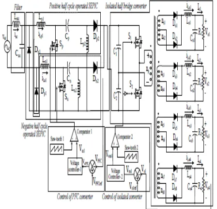
Figure 1:
Schematic diagram of the PFC converter based SMPSA. System Configuration
The design of proposed power supply with four
directed dc output voltages is appeared in Figure.1.
At the info side, DBR is disposed of by utilizing
two SEPICs. The upper converter works in the
positive half cycle and the lower one work in the
negative half cycle of the information air
conditioning voltage. The exchanging frequency
of both the converters is set at 20 kHz for
effective control. The outline of output inductors
for both the converters is completed in DCM to
decrease the intricacy in control. The control of
the output voltage can take care of wide varieties
in the information voltage and the load. The
output dc voltage (V
PFC) is detected and
contrasted and a reference voltage ((VPFCref) from
which the voltage mistake is acquired (VePFC=
V
PFCref-V
PFC) which is given to a corresponding
event that St<Vcc1 and V
acis certain, at that point
Sp is on, else Sp stays off. St speaks to the
exchanging signals for the bridgeless air
conditioning dc converter. The width of these
PWM beats shifts as indicated by the output of the
PI voltage controller-1 so that the output dc
voltage VPFC is directed adequately which is,
thusly, nourished to the disconnected half
extension converter in the second stage to acquire
different secluded directed output voltages. Thus,
the width of PWM heartbeats changes as needs be
to keep up dc output voltage VPFC steady. The
seclusion is affected through multi winding high
frequency transformer (HFT). An inside tapped
arrangement is picked at the output side to
decrease the conduction misfortunes. All the
optional windings are controlled through one
control circle. The most elevated appraised
optional twisting of the HFT is chosen for voltage
detecting. The distinction between the output
voltage (Vo1) and reference voltage (Vo1ref) is
encouraged to another PI voltage controller-2
which output is contrasted and another high
from
shoot-through
blame.
The
confined
converter is worked in CCM to take the upside of
decreased stretch. In the event that the load in any
of the winding changes, the obligation cycle
changes in like manner to guarantee managed dc
voltage outputs. The reaction of alternate outputs
is slower than the one where the output voltage is
detected.
B. Operating Principle
The operation of the front end converters and the isolated converter are described independently as follows:
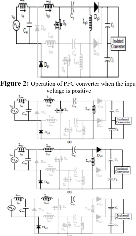
1) Operating principle of front end converter
Amid the positive half cycle of the information
primary mode, the high frequency switch Sp turns
on, the information inductor Lp1 begins putting
away the vitality which is exchanged from the
single stage air conditioning mains as appeared in
Figure. 3a. Diode Dp1 finishes the present way. In
the second mode, Sp is killed and diode Dp2
begins directing. The vitality in output inductor
Lp2 begins diminishing to zero which is appeared
in Figure. 3b. In the last exchanging state, the
current in the output inductor stays zero until the
begin of next exchanging cycle. This mode
guarantees the DCM operation as appeared in
Figure. 3c.
2) Operating principle of isolated converter
Two high frequency switches are turned on and off
on the other hand in one exchanging cycle. In this
way, the operation of the converter in one portion
of the exchanging cycle is the same as that of the
other half cycle. In the primary half cycle, the
upper switch S1 is turned on. The diodes on the
auxiliary side (Do1, Do3, Do5 and Do7) begin
directing and the inductors (Lo1-
Figure 3:
Operating modes of bridgeless PFC converter when the input voltage is positiveLo4) in all the optional windings begin putting
away vitality. At the point when the inductor
current achieves its most extreme esteem, upper
turn S1 is killed. All the channel capacitors release
through the loads to keep up dc output voltages as
consistent. In the following half cycle of the PWM
period, the upper turn is killed. The auxiliary
diodes (Do1-Do8) are swung on to free-wheel the
inductors streams. The current in every single
auxiliary winding scratch off center flux so that net
voltage crosswise over HFT ends up noticeably
zero. A similar inductor charging and releasing
happen in next half exchanging cycle with the
lower switch S2.
III. DESIGN OF PROPOSED BRIDGELESS
CONVERTER BASED SMPS SYSTEM
The design of proposed bridgeless converter based SMPS is described in the following section.
A. Design of Proposed SMPS System
The design for the positive half cycle operated PFC converter is carried out here. The negative half cycle operated converter is designed in the same way. The average voltage Vacav is calculated as,
The duty cycle D of the PFC buck-boost converter is expressed as the ratio of its output dc voltage to the sum of output dc voltage and input voltage.
Irrespective of variation in the input voltage from 170V to 270V, the output voltage is maintained constant at design of the PFC converter.
The input inductor value is calculated for the
permitted ripple of 40% of input current.
Where, f is the switching frequency of the PFC converter. The critical conduction parameter is given as,
Where, n is taken as 1 for the non-isolated PFC converter. To operate the PFC converter in DCM, the conduction parameter should be taken less than Ka for efficient control. Hence, it is selected as 0.08.
The equivalent value of inductance of the PFC
converter is given as,
,Therefore, the output inductor value is calculated as,
The selected value of output inductor is 100 μH to ensure DCM condition in all operating conditions of input voltages, load and unity PF operation at a low input voltage.
The intermediate capacitor value is estimated as,
where, ωr is the angular frequency (ωr=2πfr). A fr is considered as 2000Hz (f>fr>fL). A capacitor value of 0.22μF is selected for the hardware implementation. An L-C filter is used at the input side to mitigate higher order harmonics. The maximum value of the capacitor is as,
The filter capacitor value is selected such that it is less than Cac. Hence, a 330nF capacitor is selected in hardware implementation.
The filter inductor Lac is calculated for mitigating high order harmonics close to 5 kHz frequency.
The input capacitors of the isolated half bridge dc-dc converter act as the output filter capacitors for the PFC converter. So, the design of the capacitor is important to eliminate the second order harmonic component as well as to provide maximum power for that duration when input voltage falls. This is very crucial for PC power supplies as the rating of the capacitor affects the size and the cost of the overall SMPS.
The expression for calculating the capacitor to
reduce second order harmonic is as,
The hold-up capability can be estimated as,
where, thold-up is the holdup time of the capacitor, Po is the maximum output power, VPFC m is the minimum
output voltage (2% ripple is considered) and VPFC min
is the minimum voltage at which the output voltage holds regulation.
Therefore, to maintain 10ms hold-up time, the required capacitance is calculated as,
Two capacitors are connected in series. Therefore, the value of C1=C2=0.679 mF. The selected value of the capacitors is 0.6mF each to meet both the conditions. The calculation of inductance for the secondary winding with highest rating is shown here, while the calculation for rest of the secondary windings remains same. The inductance Lo1 is expressed as,
Similarly, the inductances for the other secondary windings are calculated as 9.5 μH, 6.8 μH and 1.5 mH.
Extension
Fuzzy Logic Controller
Fuzzy logic is a complex mathematical method that allows solving difficult simulated problems with many inputs and output variables. Fuzzy logic is able to give results in the form of recommendation for a specific interval of output state, so it is essential that this mathematical method is strictly distinguished from the more familiar logics, such as Boolean algebra.
Membership Functions
a)Error
b)Change in error
c)Output
Advantages of Fuzzy Controller over PI Controller
Usage of conventional control "PI", its reaction is not all that great for non-linear systems. The change is striking when controls with Fuzzy logic are utilized, acquiring a superior dynamic reaction from the system. Or
execution under parameter varieties, load unsettling powers, and so forth. As of late, Fuzzy Logic Controllers (FLCs) have been presented in different applications and have been utilized as a part of the power devices field. The benefits of fuzzy logic controllers over ordinary PI controllers are that they needn't bother with a precise scientific model, Can work with uncertain information sources and can deal with non-linearities and are more dynamic than traditional PI controllers.
Case1 : Full Load condition
Vac
Iac
VPFC
V01
I01
V02
I02
V03
V04
I04
ILP1
ILn1
Vcp
Vcn
ILp2
ILn2
Vsp
Vsn
Isn
Case2: Load Changing Condition
Vac
Iac
Vpfc
V01
I01
V02
I02
I03
V04
I04
Case3: Supply Voltage_170v
Vac
Iac
Vpfc
V01
I01
V02
V03
I03
V04
I04
Case4: Supply Voltage_270v
Vac
Iac
Vpfc
V01
I01
I02
A bridgeless non-separated SEPIC based power supply has been proposed here to alleviate the power quality issues unavoidable in any normal PC control supply. The proposed control supply can work elegantly under wide assortments in data voltages and weights. The layout and entertainment of the proposed control supply are at first passed on to show its improved execution. Further, an exploration focus display is developed and examinations are coordinated on this model. Test comes to fruition gained are seen to be as per the reproduced execution. They affirm the way that the power quality issues at the front end are eased and accordingly, the proposed circuit can be a recommended respond in due order regarding PCs and other near machines.
V. REFERENCES
[1] D. O. Koval and C. Carter, “Power quality characteristics of computer loads,” IEEE Trans.on Industry Applications, vol. 33, no. 3, pp. 613- 621, May/June1997.
[2] Abraham I. Pressman, Keith Billings and Taylor Morey, “Switching Power Supply Design,” 3rd ed., McGraw Hill, New York, 2009.
[5] Jih-Sheng Lai, D. Hurst and T. Key, “Switch-mode supply power factor improvement via harmonic elimination methods,” in 6th Annual IEEE Proc. on Applied Power Electronics Conference and Exposition, APEC’91, 1991, pp. 415-422.
Author’s Profile:
SUNIL KUMAR REDDY working as a Head Of The Department, EEE in MJR College of Engineering & technology, Piler, A.P, and he obtained Graduation Degree in Electrical and Electronics Engineering from SKIT in 2011, affiliated to JNTUA University, he obtained Master’s Degree in Electrical Power Systems from JNTUA, A.P. He is having 6 years of teaching experience in Engineering Colleges.
Email: skit07250@gmail.com
G.SEENAIAH working as a Assistant Professor in MJR College of Engineering & technology, Piler, A.P, and he obtained Graduation Degree in Electrical and Electronics Engineering from NCET in 2011 affiliated to ,JNTUH University, he obtained Master’s Degree in Electrical Power Systems from JNTUA, A.P. He is having 6 years of teaching experience in Engineering Colleges.
Email : seenueee4u @gmail.com
KATHI SIVAPRIYA currently she is pursuing her Master Degree in the department of Electrical & Electronic Engineering: MJR College of engineering &Technology Piler A.P. India