CSEIT183122 | Received : 20 Jan 2018 | Accepted : 24 Jan 2018 | January-February-2018 [(3) 1 : 403-418 ]
International Journal of Scientific Research in Computer Science, Engineering and Information Technology © 2018 IJSRCSEIT | Volume 3 | Issue 1 | ISSN : 2456-3307
403
Numeric Devnagari Sign Language Translator using Two Hands
Single Camera Approach
Jayshree Pansare*1, 2, Maya Ingle2
*1Department of Computer Engineering, Modern Education Society’s College of Engineering, S.P. Pune
University, Pune, Maharashtra, India
2School of Computer Science & Information Technology, Devi Ahilya Vishwavidyalaya, Indore, Madhya
Pradesh, India
ABSTRACT
Recognition of Numeric Devnagari Sign Language (DSL) using Hand Gesture Recognition System (HGRS) has become an essential tool for hearing and speech impaired to interact with commoner’s via a computer system. Our work is on the development of the proposed system Real-time Numeric Devnagari Sign Language Translator (RTNDSLT). The system architecture of RTNDSLT system is mainly comprised of five phases arranged in layered fashion from top to bottom. Vision-based, real-time and static RTNDSLT system works in cluttered background with mixed lighting conditions. This system focuses on fingertip recognition technique, Peak-and-Valley Detection algorithm, and Peak-Point Detection algorithm along with convex hull. RTNDSLT system achieves a recognition rate of 94.13% using Two Hands Single Camera approach and fingertip recognition technique.
Keywords: Devnagari Sign Language (DSL), Fingertip Recognition Technique, Two Hands Single Camera approach, Cluttered Background, Devnagari Numbers
I.
INTRODUCTION
Multiple HGRS have been developed for identification of diversified sign languages using effective techniques in real-time. Real-time dynamic HGRS recognizes hand gestures from continuous hand motion for English numbers from 0-9 based on HMM. It perceives the gesture with the recognition rate of 93.84% and works in the complex background [1]. A simulator for smartboard presents gesture detection algorithm by coordinating cues from visual, speech, and electronic slides. Specifically, intentional gestures are predicted by the modified HMM. A real-time application such as simulated smartboard and the attainability check of the prediction algorithm using hand gesture and laser pen is developed. The framework acquires an accuracy of 85% with recognition time of 1.8 Seconds [2]. Real-time HGRS
works with powerful hand tracking from depth image sequences using HMM. It obtains recognition rate of 92% in the complex background for signing digit gestures from 0 to 9 [3]. Furthermore, two real-time ASL recognizers use the desk and a wearable computer-based video respectively. Recognizer uses a single camera to track the user’s unadorned hands and HMM for recognition of sentence-level continuous ASL. The first recognizer achieves 92% word accuracy and the second recognizer accomplishes 98% accuracy for 40-word lexicon [4]. HGRS uses the real-time tracking method and HMM achieves identification rate of 90% for 20 different gestures in the stationary background [5]. Gesture segmentation and recognition system present Deep Dynamic Neural Network (DDNN) for multimodal gesture recognition. A semi-supervised hierarchical
simultaneous gesture achieves a recognition rate of 84.9% [6].
Real-time hand gesture detection and recognition system use bag-of-features, multiclass Support Vector Machine (SVM), K-means clustering, and skin detection in the cluttered background for object detection. It accomplishes detection rate of 96.23% with detection time of 0.017 Seconds per frame for training data set of 1000 samples [7]. Moreover, vision-based, real-time HGRS provides fast identification process of hand gesture and an effective feature extraction process. The system comprises of a Camshift algorithm, SVM, Discrete Fourier Transform (DFT), Fourier descriptor, and an outline feature with an accuracy of 93.4% [8]. Real-time HGRS identifies static hand gestures using Fourier descriptor, K-Nearest Neighbour (KNN), and SVM. It fulfils a recognition rate of 97.5% for 64 points using SVM [9].
Furthermore, the real-time and non-verbal system uses networked virtual environment technology to implement Telepresence that allows participants to interact with each other in cyberspace. The system works with computerized reasoning technique and semantic element extraction for recognition of Chinese Sign Language (CSL) and Japanese Sign Language (JSL). The system is appropriate for sign language detection with an identification rate of 84% [10]. Real-time HGRS detects ASL numbers from 0 to 9 using a single camera. The system works with HSV images, histogram, and Euclidian distance and accomplishes recognition rate of 93.1% [11]. HGRS presents a methodology using a neighbourhood search algorithm for cluster labelling and parameter estimation of the automated setup. Similarly, the system is based on Fuzzy C-Means (FCM) components and works for three databases (BGU, ASL, and Gripsee) in real-time. It achieves recognition accuracy of 98.9% and 98.2% for dependent and independent systems, respectively [12]. It is evident that many real-time HGRS have been developed for recognition of numbers based on
Single Hand Single Camera approach. However, there exists a wide scope to enhance HGRS design for recognition of Devnagari Sign Language (DSL) numbers using Two Hands Single Camera approach for speech and hearing impaired users to interact with general users.
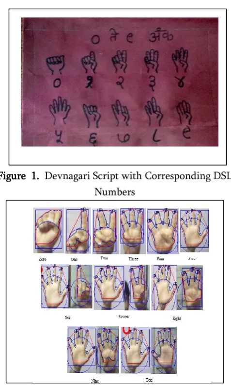
With the potential use of technology, it has become easy to design and develop the systems as per the requirements of a variety of users including hearing and speech impaired users. In this paper, we have designed a robust and reliable Real-Time Numeric Devnagari Sign Language Translator (RTNDSLT) system. The system produces verbal output in the form of voice (for the normal users) and the text (for hearing impaired users) with respect to input as numeric DSL. Our focus lies in the execution of the system in real-time for translating DSL numbers into speech. Devnagari numbers and its corresponding DSL numbers are shown in Table I and Figure 1 respectively. Figure 2 represents the invasive DSL numbers for the purpose of experimentation. In Section II, we focus on working of RTNDSLT system. Section III highlighted mainly on algorithmic approach used in RTNDSLT system. We have presented experimental results and implementation of RTNDSLT system in Section IV. In Section V, we have discussed experimental results and analysis. Comparative performance of RTNDSLT system is described in Section VI. Finally, we conclude with conclusion in Section VII.
Figure 1. Devnagari Script with Corresponding DSL Numbers
Figure 2. Invasive DSL Numbers used in Two Hands Single Camera Approach
II.
WORKING OF RTNDSLT SYSTEM
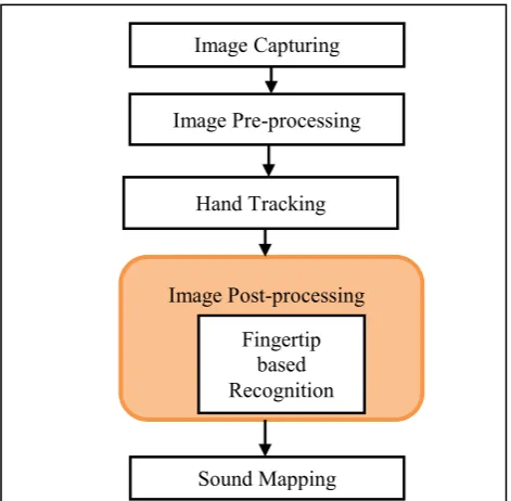
We have developed, designed, and implemented real-time recognition in RTNDSLT system for DSL numbers. Further, the architecture of RTNDSLT system is presented in Figure 3 which is fragmented into five consequent phases. These phases include namely; image capturing, image pre-processing, hand tracking, image post-processing, and sound mapping. Image capturing phase deals with capturing RGB image in the form of DSL number image using the web camera and it is assumed that the background is cluttered with mixed lighting conditions. Image pre-processing phase consists of skin segmentation as well as black and white conversion process. Skin segmentation is employed to convert YCbCr image of DSL number to RGB image and RGB image to grey image. Subsequently, grey image is translated to
binary image using black and white conversion process. Normalization technique is applied to the resultant binary image of DSL number. In this phase, median filter followed by Gaussian filter is applied on binary image of DSL number to remove the noise.
Hand tracking phase is comprised of morphological operations and region extraction. Morphological operations such as erosion and dilation are applied to filtered binary image of DSL number for obtaining smooth image whereas Region of Interest (ROI) is extracted using biggest BLOB of specified size in region extraction. This ROI is used as an input to the next phase of our proposed system i.e. image post-processing. Image post-processing phase deals with recognition of Devnagari number. We discuss this phase in detail in next sub-section. Further, recognized Devnagari number is converted to speech in sound mapping phase. Now, we discuss the vital part of our methodology i.e. image post-processing Fig. 3. This phase includes Fingertip based Recognition to enhance the performance and may be used alternately. And, the system is implemented using algorithms such as Peak-and-Valley Detection, and Peak-Point Detection algorithm. We discuss fingertip based recognition and these algorithms in subsequent sections.
A. Fingertip based Recognition Method
Figure 3. Architecture of RTNDSLT System
Figure 4. Fingertips in Hand Imag
Figure 5. Fingertip based Recognition for DSL Numbers
Implementation of the fingertip based recognition method is related to the construction of sample image dataset and input hand image of numeric DSL. This method deals with sample image dataset and fingertip based recognition. Here, we extract fingertips and store in the sample image dataset. At
the same time, fingertip based recognition may be further divided into two sub-phases namely; fingertip feature extraction and fingertip numeric DSL recognition and are discussed subsequently.
During fingertip feature extraction, the input hand image is filtered by the use of two-dimensional circular filter. The filter plays an important role in smoothing the corners of a binary image. We extract convex hull points and contour points from the filtered binary hand image. For a nonempty set of points in a plane, the convex hull is the smallest convex polygon that covers all the points in the provided set. At this stage, we create contour set of filtered hand image. The contour set of an object contains boundary (i.e. edge) points. Thus, we have developed two feature sets of an image namely; convex hull set and contour points set. Further, fingertip numeric DSL recognition sub-phase is initiated with the peak-point detection match. Convex hull set, contour points set, and peak and valley points act as input for peak-point detection match. Using this match, we may find each curve point from contour set include namely; peak and valley points. Accordingly, we discuss image contour finding and convex hull in subsequent sections.
Contour Finding Method
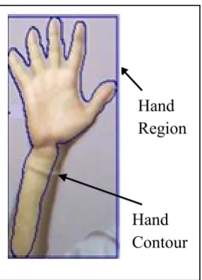
A contour is a sequence of points that are the boundary pixels of a region. Contour finding does not trace the whole pixels in an area whereas it visits only boundary pixels. Use of this technique leads to lower computation cost and the contour information that we require in decision making for fingertip detection. The contour finding method is initiated with a start point. Locating a start point may be done by scanning each row of pixels from the bottom left corner. Here, the scan of each row starts from the leftmost pixel proceeding to the right. When a white pixel is encountered, we declare that pixel as start pixel. When contour search is finished, it indicates that a hand contour is found from a smooth hand image of DSL number. A hand region and a hand contour may be plotted on RGB input image of DSL
Image Capturing
Fingertips Image Pre-processing
Hand Tracking
Fingertip based Recognition
number as shown in Figure 6. A rectangle denotes the hand region and it is a boundary box of extracted hand. A contour is denoted by the boundary edge of extracted hand. Hand boundary box size is the criteria to decide whether valid input or not. In our experiment, the hand boundary box size is defined as 30 pixels in width and
Figure 6. Hand Region and Contour of Hand Image
60 pixels in height. If any input hand image violates the boundary box criterion, it does not process further. Thus, we calculate convex hull and is discussed in subsequent section.
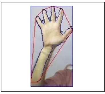
Convex Hull
We calculate the convex hull of the forearm contour in order to find the desired information. Mostly, the arm part is a smooth contour and contains important information however, it is not sufficient. The hand may contain more convex contours with the desired information. We need to explain the concept of convex polygon that is used in the convex hull. A convex polygon is a polygon that does not contain any concave part. Figure 7 (a) shows a concave part of a polygon by an arrow. The convex hull of the set of points is the smallest convex polygon that covers all the points in the set as depicted in Figure 7 (b). The hexagon in the Figure 7 (b) is the convex hull of the set of ten points. The six points used to compose the hexagon are called “hull points”. These points are used to generate the convex hull of the hand region
as shown in Figure 8. By observing the contour and its convex hull, we notice that some areas are contained in convex hull and not in the contour, are called the convexity defects. Convexity defects provide useful information about the shape of a contour.
Contour and convex hull are used in identification of peaks and valleys in hand contour. Contour points are traversed linearly with the use of three points such as X, X1, and X2, the angle between the lines as θ is computed and compared with threshold (i.e. θ <= 90°) and detected peak and valley points set is returned as output. Peaks and valleys may be detected in a Contour Plot using Peak-and-Valley Detection algorithm (Algorithm 5.3) and Counter Plot (CP) of any image is as shown in Figure 9. After the execution of Peak-and-Valley Detection algorithm, the
Figure 7. Image Convex Hull
Figure 8. Convex Hull and Convexity Defects
Hand
Region
(a) Not a Convex
(b) Polygon
Convexity Defects
Hand
Contour
(b) A Convex Hull with 10-Points
Hand
Contour
Concave
Part
Figure 9. Contour Plot (CP) for Any Image
identified peak and valley points in hand contour are denoted by a star (*) symbol as depicted in Figure 10. Out of these points, some peaks or valleys may be valid or noisy. The existence of the curve at the bottom of hand contour shows the noise peak or valley as depicted in Figure11. Let us consider H as the hand region boundary box and is as represented in eq. 1. To prevent from noise points at the bottom, the biggest hand region image is cropped with size S, as represented in eq. 2.
[ ] … (1)
[ ( ) ( )] … (2)
where, (x, y) denotes the location of H in the two dimensional image matrix, w and h are width and height of H respectively.
Now, cropped input image of DSL number is provided as input for convex hull and contour finding process. The bottom may be eliminated from the hand region by eliminating the noise as shown in Figure 11.
Figure 10. Peak and Valley Points in Hand Contour
Figure 11. Bottom of Hand Contour
Peak and valley point set consists of peak and valley points. This set does not differentiate between peak and valley in general. Thus, we need a mechanism that may discriminate peaks and valleys for recognition of fingertips. Using Peak-Point Detection algorithm (Algorithm 5.4), it is easier to extract peak point set from peak and valley point set. The peak point set is a subset of peak and valley point set. The peak point represents an open finger (or thumb). An open finger is a part of the numeric DSL gesture. To select noise free peak points from the peak and valley points, we define two important decision rules namely; enclosed circle point elimination and cross threshold distance point elimination. The enclosed circle point elimination rule predicts the noise free peak or valley points using circle strategy. Let us consider a circle C with radius R and center P, and assume a hand boundary box with the width w. All the points outside the perimeter of a circle C are considered as a useful peak or valley points and R and P as represented in eq. 3 and eq.4 respectively.
… (3)
… (4)
where, CM denotes centroid. The distance D between two points A and B may be calculated using Euclidean Distance (ED) between A and B by using eq. 5.
( ) ( ) … (5)
(a) CP for Any Image
Peak or Valley
(b) Peak and Valleys in CP
Noise Peak or Valley
Peak
Angle Valley
III.
ALGORITHMIC APPROACH USED
We have devised a RTNDSLT system for recognition of DSL numbers in cluttered background with mixed lighting conditions. Inputs to this system are running image (i.e. input binary image) and training dataset images. Fingertip based recognition method is applied simultaneously on two inputs namely; running image and training dataset images. We have established diversified algorithms such as Peak-and-Valley Detection and Peak-Point Detection along with Sample-Image-Database algorithm and are briefly discussed in subsequent sections.
A. Peak-and-Valley Detection Algorithm
We present firstly the informal description of Peak-and-Valley Detection algorithm i.e. Algorithm 1, followed by its formal description as follows:
a. Informal Description
We present now the informal description of aforesaid algorithm in this section. In Peak-and-Valley Detection algorithm, a non-empty set of hand contour points, C is an input and D is the detected peak and valley points set is the output. Firstly, we initialize peak and valley set D as empty set, index k as 1 for counter set, and index j as 0 for peak and valley set as zero. Further, the complete contour set is traversed and includes calculation of 16 points distance store in different variables such as u and v. Further, we calculate cosAngle using angle at point located at (k+16)th location. At the same time, cosAngle is computed using function dotProduct that is employed to find dot product between u and v. Furthermore, an angle in degrees is determined by applying inverse of the cos operation on cosAngle to generate angle in degrees i.e. degreeAngle θ. In our algorithm, contour points C are traversed linearly with the use of a pair of three points, the angle of a point is computed and compared with threshold and detected peak and detected peak and valley points set D is returned as output.
b. Formal Description
Algorithm 1: Peak-and-Valley Detection Algorithm for RTNDSLT System
//* Here, C is non-empty set of hand contour points and D is peak and valley points set *//
begin {Main} //* Algorithm begins *//
Step I: //* initializes detected peak and valley set as empty set *//
D = ;
Step II: //* initializes index k for contour set *// k =1;
Step III: //* initializes index j for peak and valley set as zero *//
j = 0;
Step IV: //* traverses complete contour set *// while (C(k) ≠ null)
begin
//* calculates the vector 16 points distance for u and v *//
u = C(k+16) - C(k); v = C(k +16) - C(k +32);
//* calculates angle at point located at (k+16)th location *//
cosAngle= dotProduct (u, v)/ (|u| |v|); degreeAngle=
( ) ;//*computes angle
in degree *//
if ( degreeAngle <= 90 ) //* compares an angle with threshold *//
begin
//* finds next location for assigning peak or valley point *//
j = j + 1;
D (j) = C(k +16); //* assigns peak or valley point contour set *//
//* shifts k point in contour *// k = k + 32 + 1;
k = k + 1; //* shifts k point at location next of point k *//
end if
end while
return D; //* detects the peak and valley points set as output *//
end. {Main} //* Algorithm ends*//
B. Peak-and-Valley Detection Algorithm
We present firstly the informal description of Peak-Point Detection algorithm i.e. Algorithm 2, followed by its formal description as follows:
a. Informal Description
We present now the informal description of Point Detection algorithm in this section. In Peak-Point Detection algorithm, various inputs are used such as A Peak and Valley (APV) point set, the width (w) of the hand region boundary box, a non-empty set of Convex Hull (CH) point of hand, Revised centroid i.e. Center of Mass (CM) of convex hull, and displaced centroid CM(1) in x and CM(2) in y directions and output is a set of Peak Points (PP). Here, we compute revised centroid CM using displaced centroids CM(1) in x direction and CM(2) displaced by 20 points in y direction. Further, we calculate radius r by applying half of hand region boundary box width w. We initialize peak point set PP with the empty set and index i as 0 for peak point set since it is empty along with index k as 1 for convex hull set and traverse it till size (CH) value. At the same time, the complete peak and valley point set is visited that includes a calculation of the size of APV. Furthermore, we evaluate the Euclidean distance between convex hull centroid and APV and it is stored in distance D1. Here, D1 uses enclosed circle point elimination for checking the existence of points outside the circle of radius r. Similarly, we determine the Euclidean distance between convex hull CH and APV and it is stored in distance D2. Here, D2 is applied to check the distance with threshold T using threshold distance point
elimination. Consequently, existence of peak point PP in APV and it assigns the original peak points of peak and valley set to peak point set. And, the detected set of original peak points is returned as output. The total number of peak points of the fingers is employed in detecting desired Devnagari number.
b. Formal Description
We present now the formal description of Peak-Point Detection algorithm in this section.
Algorithm 2: Peak-Point Detection Algorithm for RTNDSLT System
//* Let APV be a peak and valley point set, w be the width of the hand region boundary box, CH be a non-empty set of convex hull point of hand, and CM be a revised centroid or Center of Mass of convex hull, CM (1) and CM (2) are displaced centroid in x and y directions respectively are the inputs and output is a set of Peak Points, PP. *//
begin {Main} //* Algorithm begins*//
Step I: //* computes revised centroid *// CM = [CM(1), CM(2)+20]; Step II: //* calculates radius (r) *// r= w/2;
Step III: //* initializes peak point set PP with empty set *//
PP = ;
Step IV: //* initializes index i as zero since it is empty *//
i =0;
Step V: //* initializes index k for convex hull set and traverse it *//
for (k =1 to size(CH)) begin
for ( index =1 to size(APV)) //* visits each peak and valley point *//
//* computes Euclidean distance between centroid and APV *//
D1= EuclideanDistance (CM,
if (D1>r) //* uses enclosed circle point
elimination *// begin
//*computes Euclidean distance between CH and APV *//
D2 = EuclideanDistance (CH(k),
APV(index));
if (D2<T) //* checks distance with
Threshold (T) *// begin
if (! exist(PP, APV(index))) //* checks existence of peak point *//
begin i = i+1;
//* assigns original peak point of APV set to PP set *//
PP(i) = APV(index); end if
end if end if end for
return PP; //* the set of original peak points as output *//
end. {Main} //* Algorithm ends*//
C. Sample-Image-Database Algorithm
We present firstly the informal description of Sample-Image-Database algorithm i.e. Algorithm 3, followed by its formal description as follows:
a. Informal Description
In our algorithm, RGB image sequences and database path are the inputs and output is sample image database (i.e. training dataset). Here, getFrame() function is used to grab the first frame from sequence video and stored in frame. Further, frame is iterated until complete video sequences are processed. At the same time, skinSegmenation() function is applied to frame for skin color filtering and stored in skinFrame as noise free frame. And, filtering is followed by morphological operations applied on skinFrame using function morphologicalImageProcessing() and resultant frame is stored in noisefreeFrame. The hand
detection process is applied on noisefreeFrame using handDetection() function and stored in handFrame. Similarly, the hand image denoted by handImage is cropped from handFrame using cropHand() function. Also, the handImage is stored along with DatabasePath. Furthermore, we extract the next sequence of video by using getNextFrame() function and stored in frame. The whole procedure is repeated and consequent frames are extracted till the video is running and it is applied in the construction of the sample database. Sample database (i.e. training dataset) is employed to store DSL numbers ranging from 0 to 10.
b. Formal Description
We present now the formal description of Sample-Image-Database algorithm in this section.
Algorithm 3: Sample-Image-Database Algorithm
//* Here, RGB image sequences and database path are the inputs and output is sample image database (i.e. training dataset). *//
begin {Main} //* Algorithm begins*//
Step I: //* grabs the first frame from sequence video *//
frame=getFrame(video);
Step II: //* iterates until complete video sequences are processed *//
while(frame!=null)
begin
skinFrame=skinSegmenation(frame); //* skin color filtering *//
//* removes noise and applies morphological operations *//
handFrame=handDetection(noisefreeFrame); //* detects hand *//
handImage=cropHand(handFrame); //* crops only hand image *//
store(DatabasePath, handImage); //*stores hand image along with database path *//
frame=getNextFrame(video); //*extracts next sequence *//
end while //* forms sample database *//
end {Main} //* Algorithm ends*//
IV.
EXPERIMENTAL SETUP AND
IMPLEMENTATION
In our experimentation, there exist some hardware and software requirements. The hardware requirements include processor 3.06 GHz, RAM 1 GB, web camera of resolution 10 Mega Pixel, web camera frame rate 30 Frames/ Sec. On the other hand, software requirements cover Windows XP, MATLAB 2012, and web camera driver. The web camera and light source must be located in front of the user. We have implemented RTNDSLT system using five phases of architecture such as image capturing, image pre-processing, hand tracking, image-post processing, and sound mapping.
a. Implementation Of Pre-Requisite Phases In image capturing phase, the system parameters and resources are initialized. Basically, this phase is profoundly concerned with appropriate installation of web camera and capturing of images of numeric DSL. The web camera must be placed in front of user and captures RGB image in the form of a numeric DSL image. Images of numeric DSL are captured in RGB color format with the frame size of [320*240] pixels in cluttered background along with mixed lighting conditions. Configuration of camera deals with the initialization of parameters such as high brightness (145-175 Lumens), frame rate (30 Frames/ Sec) and frame interval (1 or 3). Thus, the captured
images will be in the form of digital frames. Every first (or third) frame is extracted from the input image frame buffer and finally RGB image will be produced as an output.
The RGB image captured in previous phase acts as input to image pre-processing phase. It consists of two main sub-tasks namely; skin segmentation and black and white conversion process. Skin segmentation process is performed using the MATLAB function rgb2ycbcr that converts RGB image into YCbCr color format. Here, Y stands for the luminance component; Cb and Cr are the blue-difference and red-difference chrominance components respectively. In YCbCr image, chrominance pixels ranges are used for skin pixel detection whereas luminance is not used in skin segmentation. If YCbCr image pixels lie within the defined ranges of chrominance, the pixels are considered to be skin color pixels. The remaining pixels are assigned as black color values that are used for background subtraction. Further, the non-pixel values are set to black and skin pixel values are assigned as the white pixel values in black and white conversion process.
tracking of hand object in the human image. The noise free image obtained after morphological operation, acts as the input in this phase. The input image contains sub-images as regions and these regions are labeled with a use of eight pixel connectivity. We have calculated the area of each labeled region as area set and selected the largest area from area set. This selected largest region is set as true value (white pixel) and other remaining regions are set to be false as a value (black pixel). At this stage, the image contains only the biggest region and may be called as a BLOB. This BLOB represents the only hand in the human image.
b. Implementation Of Image Post-Processing Phase The prime focus of post-processing phase is the recognition of numeric DSL with low execution time and higher recognition success rate. This phase may be accomplished using Fingertip Recognition to enhance the performance. Accordingly, the system is designed, developed, and implemented using Peak-and-Valley Detection (Algorithm 1), and Peak-Point Detection (Algorithm 2) algorithm. These algorithms are used to offer recognized Devnagari numbers. While using these algorithms for recognition of eleven DSL numbers, our input is a filtered (smooth) one handed (i.e. 0 to 5) and two handed (i.e. 6 to 10) images of DSL numbers with size [320*240] pixels. In the first step, hand region crops from the input image and then cropped hand image of DSL number is resized with [M*N] pixels (same as sample image resized before feature extraction).
Sound mapping phase is used to generate sound in respect of recognized Devnagari number. Audio signal processing is required to produce the sound by the speaker. We have developed a wave library that consists of wave files for each Devnagari number (i.e. from 0 to 10) in RTNDSLT system. At this stage, these recorded wave files are used to produce sound (digital audio). In digital audio, the most commonly used audio sampling rates are 44.1 kHz, 48 kHz, 88.2 kHz, 96 kHz, and 192 kHz. It has been observed that lower sampling rates are beneficial for small data
size and easier storage and transport. According to Nyquist-Shannon theorem, sampling rates higher than 60 kHz may not supply more usable information for human listeners. The Audio Engineering Society recommends 48 kHz sample rate for most applications. On the other hand, it suggests 44.1 kHz for Compact Discs (CDs) and other consumer uses. In our experimentation, we have used the audio sampling rate at 11025 Hz in our recording function. It may be observed that sampling rate of 11025 Hz is one quarter of the sampling rate of audio CDs. It is used for MPEG audio and for audio analysis of subwoofer band passes. Here, we have loaded the wave library and sent the audio signals to the speaker for generating sound for numeric DSL.
V.
EXPERIMENTAL RESULTS AND ANALYSIS
Real-Time Numeric Devnagari Sign Language Translator (RTNDSLT) system is devised for translation of 11 DSL numbers into verbal output in the form of voice. It is mainly concerned with the detection of DSL numbers using Two Hands Single Camera in cluttered background with mixed lighting conditions. The architecture of RTNDSLT system is fragmented into five consequent phases namely; image capturing, image pre-processing, hand tracking, image post-processing, and sound mapping. Image capturing phase deals with capturing RGB in the form of a DSL number image. In image post-processing phase, RGB image is converted to YCbCr
image MATLAB function rgb2ycbcr and
post-processing phase. The prime focus of post-post-processing phase is the recognition of numeric DSL with low execution time and higher recognition success rate.
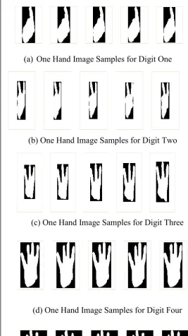
Therefore, we have designed, developed and implemented RTNDSLT system using fingertip based recognition. At the same time, we have established algorithms such as Peak-and-Valley Detection (Algorithm 1), and Peak-Point Detection (Algorithm 2) algorithm. Moreover, we have applied on Sample-Image-Database (Algorithm 3) algorithm used for storage of images in the training dataset. Training dataset required for implementation of fingertip based recognition method is constructed using a program for Fingertip Knowledge Dataset is used to generate training dataset for fingertip based recognition method. Moreover, training dataset is constructed using Sample-Image-Database algorithm (Algorithm 3). We have constructed training dataset of size 1100 samples using this algorithm. In this context, we present sample image database for one hand image samples for five digits is as shown in Figure 12 ranging from one to five as depicted in Figure 12 (a) to Figure 12 (e) respectively. Further, minimum Euclidean distance between training dataset images feature vectors and running image (i.e. extracted BLOB) feature vector is calculated. Least Euclidean distance is used to recognize the best suitable pattern as Devnagari number. Lastly, sound mapping phase is applied to convert Devnagari number (i.e. text) to speech using audio files.
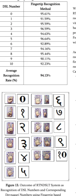
Consequently, we have evaluated experimental results of our RTNDSLT system in real-time using fingertip based recognition method. Accordingly, recognition rate achieved by RTNDSLT system using fingertip based methods is presented in Table 2. It is observed that RTNDSLT system achieves a recognition rate of that recognition rate is 94.13% using the fingertip based recognition method. Here, recognition of DSL numbers and corresponding Devnagari number using fingertip based method act as outcome of RTNDSLT system. The outcome using aforesaid BOF methods is represented in Figure 13.
Figure 12. One Hand Image
(a)
One Hand Image Samples for Digit One
(b) One Hand Image Samples for Digit Two
(c) One Hand Image Samples for Digit Three
(d) One Hand Image Samples for Digit Four
Table 2. recognition rate of rtndslt system using fingertip recognition method
DSL Number Fingertip Recognition Method
0 95.61%
1 91.59%
2 95.59%
3 96.59%
4 94.63%
5 96.64%
6 92.89%
7 94.16%
8 95.44%
9 90.11%
10 92.23%
Average Recognition
Rate (%)
94.13%
Figure 13. Outcome of RTNDSLT System as Recognition of DSL Numbers and Corresponding
Devnagari Numbers using Fingertip based Recognition Method
VI.
COMPARATIVE PERFORMANCE OF
RTNDSLT SYSTEM
We now present the comparative performance of RTNDSLT system with other HGRSs used for recognition of DSL numbers. On the basis of some vital factors such as approaches, techniques, background, and recognition rate, a comparative performance is presented as shown in Table III. Following are the important observations associated with the execution of RTNDSLT system:
As compared to existing HGRSs, RTNDSLT system recognizes 11 DSL numbers from 0 to 10 using the fingertip recognition method. It attains the recognition rate of 94.13% using Two Hands Single Camera approach in the cluttered background.
Numeric HGRS is designed for identification of DSL numerals using histogram and skin color segmentation techniques, accomplishes the detection rate of 93.1% including mixed lighting conditions in the static background. HGRS_TM is developed to recognize 10 DSL
numbers using template matching, acquires the detection rate of 90.1% using Single Hand Single Camera approach in the static background.
HGRS_FT is designed for detection of DSL numbers using FT, achieves a recognition rate of 89% using Single Hand Single Camera approach in static background.
Using EOH in HGRS_EOH, DSL numbers are recognized with the recognition rate of 86.2 % along with Single Hand Single Camera approach in the complex background has been reported.
HGRS_DCT is devised using DCT technique to detect DSL numbers and acquires the lowest detection rate of 82.2% using Single Hand Single Camera approach in the complex background.
recognition techniques for identification of 11 DSL numbers accomplishes the lowest recognition rate of 58.88% and 43.3% respectively in cluttered background using Two Hands Single Camera approach.
However, it is evident from Table III that highlighted the performance of RTNDSLT system shows effective outcome as compared to other HGRSs for identification of DSL numbers.
Table 3. Comparative Performance of HGRSs and RTNDSLT system
VII.
CONCLUSION
Auditory handicapped users normally make use of sign language for communication purpose. In order for an ordinary person to communicate with deaf people, we have devised Real-time Numeric Devnagari Sign Language Translator (RTNDSLT) system. It mainly deals with the detection of DSL numbers using Two Hands Single Camera approach in cluttered background. The architecture of RTNDSLT system is fragmented into five consequent phases namely; image capturing, image pre-processing, hand tracking, image post-pre-processing, and sound mapping. We have introduced fingertip based recognition method in image post-processing phase to enhance the performance of system in real-time. Further, we have implemented a system using fingertip based recognition algorithms such as Peak-and-Valley Detection, and Peak-Point Detection
algorithm. Two handed DSL number images and sample database images are the inputs provided to RTNDSLT system. Here, DSL number images captured using web camera of resolution 10 Mega Pixels at a distance of 1 meter from camera with mixed lighting condition. These captured images are stored in training dataset using Sample-Image-Database algorithm and forms training dataset of size 1100. The system identifies 11 DSL numbers and accomplishes the recognition rate of 94.13% using fingertip based recognition method with recognition time of 0.03 seconds.
VIII.
REFERENCES
[1]. M. Gharasuie, et. al., "Real-time Dynamic Hand Gesture Recognition using Hidden Markov Models", in Proceedings of 8th Iranian Conference on Machine Vision and Image Processing (MVIP), 2013,pp. 194-199.
[2]. F. Wang, et. al., "Simulating a Smartboard by Real-time Gesture Detection in Lecture Videos", IEEE Transactions on Multimedia, vol. 10, no. 5,pp. 926-935, 2008.
[3]. H. Zhu and C. Pun, "Real-time Hand Gesture Recognition from Depth Image Sequences", in IEEE Proceedings of International Conference on Computer Graphics, Imaging and Visualization,2012, pp. 49-52.
[4]. T. Starner, et. al., "Real-time American Sign Language Recognition using Desk and Wearable Computer based Video", IEEE Transactions on Pattern Analysis and Machine Intelligence, vol. 20, no. 12, pp. 1371-1375, 1998.
[5]. F. Chen, et. al., "Hand Gesture Recognition using a Real-time Tracking Method and Hidden Markov Models", Image and Vision Computing, vol. 21,pp. 745-758, 2003.
[6]. D. Wu, et. al., "Deep Dynamic Neural
Networks for Multimodal Gesture
[7]. N. Dardas and N. Georganas, "Real-time Hand Gesture Detection and Recognition using Bag-of-Features and Support Vector Machine Techniques", IEEE Transactions on Instrumentation and Measurement, vol. 60, no. 11, pp. 3592-3607, 2011.
[8]. R. Zhang, et. al., "Hand Gesture Recognition with SURF-BOF based on Gray Threshold Segmentation," in IEEE Proceedings of 13th International Conference on Signal Processing (ICIP),2016, pp. 118-122.
[9]. H. Gamal, et. al., "Hand Gesture Recognition using Fourier Descriptors", in IEEE Proceedings of 8th International Conference on Computer Engineering and Systems (ICCES), 2013, pp. 274-279.
[10]. Z. Liu, et. al., "Research on Chinese-Japanese Sign Language Translation System", in IEEE Proceedings of 5th International Conference on Frontier of Computer Science and Parameter Estimation for the Automated Setup of a Hand-Gesture Recognition System", IEEE Transactions on Systems, Man, and Cybernetics-Part A: Systems and Humans, vol. 35, no. 6,pp.932-944,2005. Subjective Quality of Service of Conversational Mobile Multimedia Applications Delivered over the Internet: A Methodology Study", IEEE Transactions on Multimedia, vol. 4, no. 1, pp.59-67,2002.
[15]. S. Nikhil, et. al., "Design and Development of a DSP Processor based Reconfigurable Hand
Gesture Recognition System for Real-time Applications", in IEEE Proceedings of International Conference on Signal and Image Processing, 2010,pp.39-44.
[16]. G. Mao, et. al., "Real-time Hand Detection and Tracking against Complex Background", in IEEE Proceedings of 5th International Conference on Intelligent Hiding and Multimedia Signal Processing, 2009, pp. 905-908.
[17]. Y. Zhu, et. al., "Toward Real-time Human-Computer Interaction with Continuous Dynamic Hand Gestures", in IEEE Proceedings of 4th International Conference on Automatic Face and Gesture Recognition, 2000, pp. 544-549.
[18]. Y. Guan and M. Zheng, "Real-time 3D Pointing Gesture Recognition for Natural HCI", in IEEE Proceedings of 7th World Congress on Intelligent Control and Automation, 2008, pp.2433-2436.
[19]. J. Wei, et. al., "The Hand Shape Recognition of Human Computer Interaction with Artificial Neural Network", in IEEE Proceedings of International Conference on Virtual Environments, Human-Computer Interfaces and Measurement Systems, 2009, pp. 350-354. [20]. A. Dib, "A Real-time Visual SLAM for RGB-D
Cameras based on Chamfer Distance and Occupancy Grid", in IEEE/ACME Proceedings of International Conference on Advanced Intelligent Mechatronics, 2014, pp. 652-657. [21]. Y. Fang, et. al., "A Real-time Hand Gesture
Recognition Method", in Proceedings of International Conference on Electronics, Communications, and Control (ICECC), 2011, pp. 2475-2478.
[23]. A. Chan, et. al., "Real-time Tracking of Hand Gestures for Interactive Game Design", in IEEE Proceedings of International Symposium on Industrial Electronics (ISIE), 2009, pp. 98-103. [24]. J. Lee, et. al., "Real-time Gesture Interface
based on Event-Driven Processing from Stereo Silicon Retinas", IEEE Transactions on Neural
Networks and Learning Systems,
vol.25,no.12,pp.2250-2263,2014.
[25]. P. Huang, et. al., "Real-time Stereo Matching For 3D Hand Gesture Recognition", in IEEE Proceedings of International Society Design Conference (ISOC), 2012, pp. 29-32.
[26]. Y. Yao and C. Li, "A Framework for Real-time Hand Gesture Recognition in Uncontrolled Environments with Partition Matrix Model based on Hidden Conditional Random Fields",in IEEE Proceedings of International Conference on Systems, Man, and Cybernetics, 2013,pp.1205-1210.
[27]. N. Bhat, "Real-time Robust Hand Gesture Recognition and Visual Servoing", in IEEE Proceedings of Annual India Conference (INDICON), 2012, pp. 1153-1157.
[28]. J. Lee, et. al., "Real-time Gesture Interface based on Event-Driven Processing from Stereo Silicon Retinas", IEEE Transactions on Neural Networks and Learning Systems, vol. 25, no. 12,pp. 2250-2263, 2014.
[29]. P. Neto, et. al., "Real-time and Continuous Hand Gesture Spotting: an Approach based on Artificial Neural Networks", in IEEE Proceedings of International Conference on Robotics and Automation, 2013, pp. 178-183. [30]. X. Li, et. al., "Hand Gesture Recognition by
Stereo Camera using the Thinning Method", in IEEE Proceedings of International Conference on Multimedia Technology, 2011, pp. 3077-3080.
[31]. R. Mohana and A. Reddy, "Signer-Independent SLR System using PCA and Multi-class SVM", Praise Worthy Prize International Review on Computers and Software (IRESOE), vol. 9, no.
12, 2014. doi:
https://doi.org/10.15866/irescos.v9i12.4838 [32]. J. Pansare and M. Ingle, "Real-time Static Hand
Gesture Recognition for American Sign Language (ASL) in Complex Background", Journal of Signal and Information Processing, vol. 3, no. 3,pp. 364-367, 2012.
[33]. J. R. Pansare and M. Ingle, "A Real-time Devnagari Sign Language Recognizer(α-DSLR) for Devnagari Script", Worlds Conference on Smart Trends in Systems, Security and Sustainability(WS4 2017), 2017.
[34]. J. R. Pansare and M. Ingle, "Comprehensive Performance Study of Existing Techniques in Hand Gesture Recognition System for Sign Languages", International Journal of Computer Science and Information Technology, vol. 7, no. 3,pp. 1343-1347, 2016.
[35]. J. R. Pansare and M. Ingle, " Vision-based approach for American Sign Language Recognition using Edge Orientation Histogram", IEEE, pp. 86-90, 2016. doi:10.1109/ICIVC.2016.7571278
[36]. J. R. Pansare, et al., "Real-time static hand gesture recognition system in complex background that uses number system of Indian Sign Language," Int. J. Adv. Res. Comput. Eng. & Technology, vol. 2, no. 3,pp. 1086-1090, 2013.
[37]. J. R. Pansare, et al., "Real-time static Devnagri Sign Language translation using histogram," International Journal of Advanced Research in Computer Engineering & Technology, vol. 2, no. 4,pp. 1-5, 2013.