C
o m p u t i n g
S
u r f a c e
Overview of the Control Area Network (CAN)
The information supplied in this document is believed to be true but no liability is assumed for its use or for the infringements of the rights of others resulting from its use. No licence or other rights are granted in respect of any rights owned by any of the organisations mentioned herein.
This document may not be copied, in whole or in part, without the prior written consent of Meiko World Incor-porated.
© copyright 1995 Meiko World Incorporated.
The specifications listed in this document are subject to change without notice.
Meiko, CS-2, Computing Surface, and CSTools are trademarks of Meiko Limited. Sun, Sun and a numeric suffix, Solaris, SunOS, AnswerBook, NFS, XView, and OpenWindows are trademarks of Sun Microsystems, Inc. All SPARC trademarks are trademarks or registered trademarks of SPARC International, Inc. Unix, Unix System V, and OpenLook are registered trademarks of Unix System Laboratories, Inc. The X Windows System is a trade-mark of the Massachusetts Institute of Technology. AVS is a tradetrade-mark of Advanced Visual Systems Inc. Verilog is a registered trademark of Cadence Design Systems, Inc. All other trademarks are acknowledged.
Circulation Control:
Meiko’s address in the US is:
Meiko
130 Baker Avenue Concord MA01742
508 371 0088 Fax: 508 371 7516
Meiko’s address in the UK is:
Meiko Limited 650 Aztec West Bristol
BS12 4SD
Tel: 01454 616171 Fax: 01454 618188
1.
The Control Area Network . . . .
1
Introduction. . . 1
Network Hierarchy . . . 1
CAN Messages . . . 2
Network Protocol . . . 3
Prioritisation . . . 4
Network Error Detection and Recovery . . . 4
Example — Snooping the CAN . . . 5
Appendix A — Packet Format . . . 7
Header Data . . . 7
1
The Control Area Network
1
Introduction
The Control Area Network (CAN) is a low bandwidth serial network. It is used by the CS-2 to carry control, diagnostic, and remote console traffic between proc-essors. The CAN is independent of the CS-2 data network and does not therefore impact on its performance.
An understanding of the CAN is not required for normal operation of the CS-2. It is typically used by the resource management system to maintain the machine database, and by Pandora to create remote console connections and to gather component operating status. The information in this document is therefore pro-vided for information only.
Network Hierarchy
The CAN is hierarchical, with the number of nodes on each network limited (by the electrical characteristics of the CAN transceivers) to around 30 nodes.
2 S1002–10M140.00
1
Figure 1-1 L-CAN Connections within a Processor Module
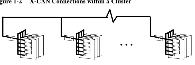
The modules within a Cluster (3 bays, up to 24 modules) are interconnected by the X-CAN, and the interconnection of Clusters is via the G-CAN. The transfer of network traffic from the L-CAN to the X-CAN is handled by each module’s controller, whereas the transfer from X-CAN to G-CAN is via nominated routers (selectable from Pandora).
Figure 1-2 X-CAN Connections within a Cluster
CAN Messages
A node requests status information from, or sends control requests to, another CAN node by sending a message to it. The information or function that is re-quired by the sender is specified by addressing an object at the recipient. Objects are either hardware devices or software functions, the mapping from an object id
Processor Board (max. 4 per module)
SPARC Processor (max. 4 per board)
H8 Board Controller (1 per board)
H8 Module Controller
L-CAN within Module
4 S1002–10M140.00
1
Prioritisation
Message priorities are used at two stages; during arbitration between CAN de-vices on the L-CAN, and during routing between network levels by a routing processor. The two stages of prioritisation are represented by the two priority bits in the CAN message packet; the header defines the priority between CAN devic-es (either 0 for high priority, or 1 for low), and addrdevic-ess data specifidevic-es the priori-tisation for routed messages. A high priority message might indicate a power supply failure, whereas less urgent messages (switch errors) are recorded by low priority messages. During routing the priority in the message’s address field is used to reduce congestion at the routers and on the X-CAN/G-CAN networks, and may be modified by the router processors to give highest priority to message responses and those making their way down the CAN hierarchy. Note that a low priority message sent to a node can be overwritten by a high priority message, causing the low priority message to be scrapped.
Network Error Detection and Recovery
Packets are acknowledged (ACK’ed) if they reach their destination and are inter-preted correctly. A not-acknowledge (NACK) is sent if they fail to be correctly interpreted at their destination.
Reasons for failure are:
•
Bad message. Perhaps the sender attempted to write to a read-only object, or an object that doesn’t exist.•
Hardware errors. Either the message or the acknowledgement failed.•
Hardware overruns. No spare input buffer at the transceiver.Bad messages, or messages to non-existent objects, are signalled to the sender by the return of a not-acknowledge packet.
The Control Area Network 7
1
Appendix A — Packet Format
CAN packets are 10 bytes in length consisting of 2 bytes of header information, 4 bytes address data, and an optional 4 bytes of message data.
Header Data
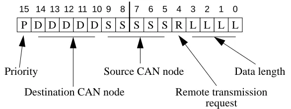
The 2 byte message header identifies the source node, destination node, and mes-sage priority.
Figure 1-3 Message Header (2 bytes)
The fields in the packet header have the following meanings:
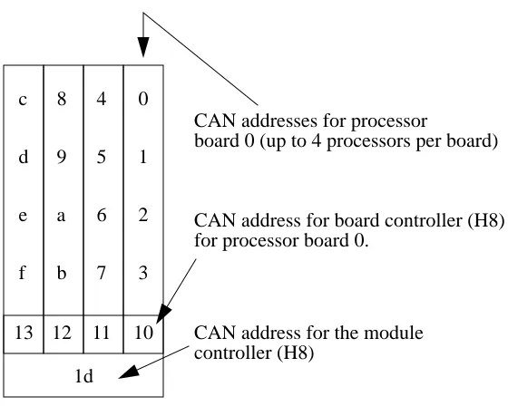
Within a module CAN node ids are allocated as shown in Figure 1-5.
Bit(s) Meaning
15 Message priority (for arbitration on the L-CAN). 0 is high, 1 is low.
14-10 Destination CAN node id. (in the range 0–29).
9-5 Source CAN node id. (in the range 0–29).
4 Remote transmission request (always 1 for the CS-2).
3-0 Length of following data. This will be either 4 or 8 for the CS-2; 4 bytes are required for the address data, and an optional 4 bytes for object-specific data.
P D D D D D S S S S S R L L L L
7 6 5 4 3 2 1 0 15 14 13 12 11 10 9 8
Priority
Destination CAN node
Source CAN node
Remote transmission Data length
8 S1002–10M140.00
1
Address Data
The action performed at the destination node is specified by the address data. This defines the message type (Write to object, read from object etc.), and the ad-dress of the object that is to be targeted.
Figure 1-4 Object Addressing (4 bytes)
The fields in the address data have the following meanings:
Bit(s) Meaning
31 Message priority for arbitration by the X-CAN/G-CAN routers. 0 is high, 1 is low.
30-28 Message type (see below).
27-0 The address of the object that the transaction is to apply to. This if a full machine address consisting of a 6 bit cluster id, 6 bit module id, a 6 bit node id, and a 10 bit object id. A broadcast is specified by 111110; 111111 means never route to this level. Object id’s are listed in the header files/usr/include/sys/cankobj.h and/opt/ MEIKOcs2/etc/include/canio/canobj.h.
Object address (cluster, module, node, and object ids) AnAnAnAnAnAnAoAo
15 14 13 12 11 10 9 8
AoAoAoAoAoAoAoAo
7 6 5 4 3 2 1 0
AcAcAmAmAmAmAmAm
23 22 21 20 19 18 1716
P T T T AcAcAcAc
31 30 29 28 27 26 2524
The Control Area Network 9
1
Message types are:
Id Meaning
000 Read request; the address identifies an object to be read. For use by master CAN nodes only (typically the H8 processors).
001 Write request; the address identifies the object to be written to. For use by master CAN nodes only (typically the H8 processors).
010 Write request without acknowledge from destination; the address identifies the object to be written to. For use by master CAN nodes only (typically the H8 processors).
011 Data.
100 Write acknowledge.
101 Unused.
110 Write a not-acknowledgement.
10 S1002–10M140.00
1
Figure 1-5 CAN Addresses within a Module
0
1
2
3
10 4
5
6
7
11 8
9
a
b
12 c
d
e
f
13
1d
CAN addresses for processor
board 0 (up to 4 processors per board)
CAN address for board controller (H8) for processor board 0.