Analysis of Two Spindle Amber Charkha
Mr. Gaurao D. Surkar*1 Dr. G. V. Thakre*2Dr. M. J. Sheikh*3 Prof. U. D. Gulhane*4
Department of Mechanical Engineering, Bapurao Deshmukh College of Engineering, Sevagram, Rashtrasant Tukadoji
Maharaj Nagpur University, India *1,2,3,4
ABSTRACT:- The Charkha is a small device which can be used to spin fiber, such as cotton, into yarn. Fabric from this yarncan be used to make all sorts of clothing. Increasing demands of the cotton fabrics, now a days, has made itnecessary to increase the production of cotton fabrics. To increase the production it is necessary to study the factors affecting the performance of the women workers working on Amber charkha. Most of the Amber charkha in rural areas are handoperated (i.e. they run with the help of human energy input). This paper highlights some of thefactors which are responsible for their performance. The various factors that are affecting the productivity are technical factor, their weight and cost of the two spindle amber charkha. Each of these factorsplays an important role in the overall performance of the workers. The detailed study is carried out todesign and analysis of two spindle of Amber charkha. The basic necessity of this study is tominimize its weight and price which would help the workers forachieving better productivity with work satisfaction.
KEYWORDS:-Amber charkha , spin fiber, cotton fabrics, yarn. etc.
1. INTRODUCTION
Today era is marching towards the rapid growth of industrialization higher the rate of production higher is the profit is the requirment of today’s global marketing. Textile sector is also emerging sector. Synthetic and blended material, like polyester became available at very low price compared to Khadi. The low capacity and high cost rendered handmade fabrics most incompatible, which made weavers and artisans drift away from the loom. The in-human working conditions of the early industrialization and the confidence in the mechanical view of the world of the 19th century in the possibility of planning and creating good conditions provoked the founding of a separate science discipline. Already in 1857, Mr. Jastrzebowski from Poland proposed in the journal Nature and Industry to take care of the scientific approach regarding the problems that are imposed by work and to create a separate science in order to obtain from this science the best with the least efforts with the highest satisfaction for the own and public welfare and by acting fair with regard to the own conscience and others. He called this new scientific branch as Human Engineering or Ergonomics. This name, however, was forgotten later. Starting in the middle of the last century, many activities happened in the various countries that dealt with a scientific view of human work.
The common man shuns the handmade fabric, because of the rough texture, stale colours and unattractive designs. He likes the machine-made fabrics because of the competitive disadvantages the handmade fabric suffers from. Organizations decided to focus on the techniques to make Khadi textile acceptable with a popular appeal. It decided to conduct R&D on product diversification with new designs and fashion appeals for Khadi. Organizations chose to play the role of a technology adviser to nurture the locally available and technically qualified human-resources in the cotton region in designing of new products from Khadi. To begin with, it was decided to design handbags first.
II . LITERATURE REVIEW
Prof. G. V. Thakre (2011) suggested in order to increase the production it is necessary to study the factors affecting the performance of the women workers working on Amber charkha. Most of the Amber charkha in rural areas are hand operated. There are various medical, technical and environmental factors which affect the productivity of women workers working on Amber charkha. This paper discusses some of those factors which are responsible for this. This paper analyses by comparing the actual readings with the standard norms available in the literature. The exhaustive work has been carried out to study the different factors affecting the productivity of Amber charkha. The major requirement of the study is to provide comfortable sitting arrangement and good working environment.[1]
fabrics, now a day has made it necessary to increase the production of cotton fabrics. To increase the production it is necessary to study the factors affecting the performance of the women workers working on Amber charkha. Most of the Amber charkha in rural areas are hand operated. The various factors that are affecting the productivity are top arm is unable to give variable pressure to different pulley. one that the people should get engaged in a focused activity and create one’s own gainful employment thereby contributing to the country's economic wealth. This paper reveals the factors affecting the productivity of amber charkha.[2]
N. U. Alone, Prof. J. F. discussed on whether to control Lilliput Ginning Machine by either hand crancking or bicycleaccelerating. The principal conclusion is that leg muscles are clearly greater than arm muscles so withbicycle accelerating ready to deliver more drive/torque. This was only a general suspicion and not outlineparticular so a particular examination obliged that should be possible to get more particular answers.Pedal worked and hand cracking setup was created, utilizing Anthropometric Dimensions ofMadhya Pradesh ranch labourers, and point of interest trial Comparison between hand Cranking versusBike accelerating is figured and thought about.[3]
Haidar F. AL-Qrimli and Karam S. Khalisuggested the purpose of this work is to present a clear fundamental thought for designing and investigating straight bevel gear made of composite material. Composite materials have the advantage of being light, producing low noises, and extra loading capacities. Due to these properties, it is highly preferable over conventional materials. A comparison between different types of material used in a gear structure will be shown. The outcome shows that a new form of cheap material may be useful for designing a new type of lighter and stiffer gear, designed for robotic arm applications or any power transmission application.[4]
A. Athisaya et.al.(2014) investigated aboutGears which are the most important component in a power transmission system. Their effectiveness should not decrease with a constantprolonged application and should have well anti wear properties. The assembled gear transmits mechanical energy from a primemover to an output device. A gearbox can also change the speed, direction, or torque of mechanical energy. Gearbox isindicated when the application involves high speeds, large power transmission where noise abatement is important. Thus gearneeds to be redesigned, providing energy saving by weight reduction, providing internal damping, reducing lubricationrequirements, without increasing cost.. Composite materials offer the advantage ofa flexible design that can be tailored to the design requirements. The specific composite materials Glass filled polyamide inparticulate form is used for herringbone gears owing to better strength, recyclability, low density and less friction.Glass/epoxyis used for gear housing and shafts for strength requirements, orthotropic properties. Finite element analysis allows entiredesigns to be constructed, refined, and optimized before the design is manufactured with dynamic effects in low cost.[5]
M.S. Navle and Dr. A. V. Damale (2016) proposed a Gear trains used to transmit the power in various industrial applications. For gear train, various conflicting and dependent parameters needs to be, analyzed during its design and manufacturing. The study of conflicting dependent parameters with various optimization tools is presented in this paper as review. Total number of research papers studied are thirty-six which are further grouped in five categories like design method used, softwareused etc. The design parameters are considered for optimizations are face width, module and number of teeth on pinion and gear etc. The exhaustive literature review reviled that genetic algorithm is the most commonly used optimization technique for designing industrial gear train. The gear trains are optimized by various methods. The conventional methods have shown laborious work required. Theorigin of new evolutionary optimization methods used in gear train optimization methods shows considerable savingsin materials and weight due to reduced weights. Also the improved life of the optimized gear train shows that evolutionary optimization technique can be effectively used for gear train optimization.[6]
Working Of Two Spindle Amber Charkha
The input material to the charkha is roving/sliver which contains large number of fibres in its cross section. The numbers must be reduced to about 100 in the yarn cross section. The reduction of fibres in the cross section is effected through drafting. In charkha 3-line single-apron drafting system is used (Fig. 1). During drafting the fibres are firmly nipped between the bottom steel fluted roller and the weighted top pressure roller. The pressure is applied by spring weighting system.
The roller pairs rotate at an incremental speed resulting stretch (i.e. draft) in the material nipped between the rollers. The controlled two stage stretching operations (i.e. drafting) elongate the feed roving and bring it to the required yarn dimension from the point of view of mass per unit length.
Once the drafted product emerges from the nip of the front pair of roller, it is to be twisted to impart strength to the fibre matrix. Twist is imparted by the combination of ring and traveller. The traveller is a small loop of wire loosely mounted on the ring and hence free to move on the circular ring. The spindle which holds the package (bobbin) causes the traveller to rotate on a ring. The yarn loop between the front roller to the bobbin via the traveller, causes required force to be imparted on the traveller by the spindle. Every revolution of traveller causes the yarn to be twisted around its own axis. The twisted yarn is simultaneously wound on the package. The ring rests on a platform which is made to oscillate from bottom to top of the package at a certain frequency. As the ring moves up and down, the traveller also follows the same and hence the yarn is guided from bottom to top of the bobbin for laying.
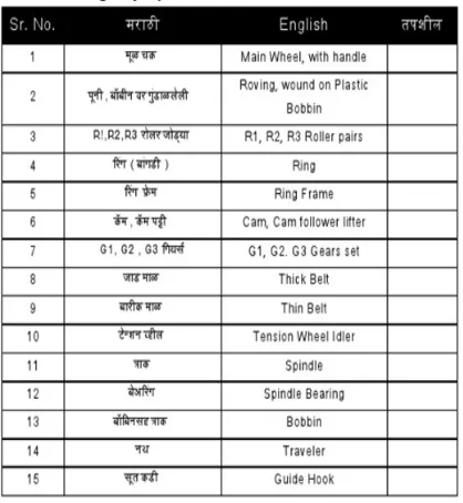
Following are the two images of two spindle charkha with naming of each part shows in table number 1:-
Table1: courty image of naming table (author-MadhavSahasrabudhe)
The systematic view of wireframe model of two spindle amber charkha which shows the gear arrangements and the working of charkha is given below
Figure B: Wireframe model of Two Spindle Amber charkha
Drafting
The bottom drafting rollers made of steel are mounted on an inclined roller stand having fixed brackets. The top rubber covered rollers are mounted in a pendulum lever arm which is pivoted in the machine frame. The lever can be swung to lift all the rollers together. The top rollers are pressed against the bottom steel rollers by spring pressure. The bottom rollers are positively driven and top rollers are surface driven.
Fig. C:Drafting arrangement of charkha
Twisting
Twist is imparted to the yarn by the rotating traveller (Fig. 2). Each revolution of the traveller imparts one turn of twist to the strand. The traveller rotates on the surface of the ring. The traveller does not have its own drive. It is dragged by the yarn that passes through it on to the bobbin surface which is mounted on the spindle. The yarn is pulled by the rotating spindle.
Mathematically the yarn twist is the ratio of traveller speed to delivery rate. The traveller speed practically being very close to spindle speed the twist is
The strength of yarn is manipulated by varying twist. Strength generally increases with twist. However too high twist make the yarn hard and also reduces productivity as twist is usually increased by reducing delivery. In order to change twist the delivery by front drafting rollers is changed.
Package Formation
For package formation the yarn needs to be wound around the package and laid uniformly across the entire length of it. As the traveller and spindle rotate in the same direction, the difference in the peripheral speeds of the traveller and the spindle causes the yarn to be wound on to the package. The speed difference is due to the lagging of the traveller relative to the spindle due to continuous delivery of yarn from front roller and traveller ring frictional drag. Since the traveller also acts as a guide for the yarn it is oscillated back and forth across the entire length of the package for laying the yarn uniformly. This oscillating movement is imparted to the ring rail which holds the ring on which the traveller runs.
Power analysis of two spindle Amber Charkha
Available power is 18 watt
FOR CALCULATING ACTUAL POWER BY WEIGHT ADDING METHOD IN PAN 1.4 kg force required to rotate the handle
Torque=force× length
= 1.4× 0.2× 9.8 ……….{ length of handle = 0.2m } T= 2.8 Nm
= …………(ref 8)
= × × . ………..{ rpm of handle is 60}
P =17.34 watt
PART 1: Power required to spinning the bobbin
I= …………(ref 8)
I= . × . ……… { bobbin wt is 150gm}
I=1.69× 10 Kgm2
RPM of bobbin is 6691 rpm
Therefore w= …………(ref 8)
= ×
w = 700
α =
=
=
α=350 r/s2
T=I×α…………(ref 8) = 1.69 × 350 × 10-5
T = 5.9× 10⁻³nm
=
=2 × 6691 × 5.91 × 10 60
P=4.14 = 5 watt { For 1 bobbin } P1=10 watt { For 2 bobbin }
Now Power losses through belt and gear Drive
1) First Stage=n=95% …………(ref 8)
= 10/0.95
= 10.52 watt
2) Second Stage=n=95% …………(ref 8)
= 10/0.95
3)Third Stage=n=98% …………(ref 8)
= 10/0.98
= 11.31 watt
Torque applied is given at gear T=12
=
11.27= × × ----{rpm of gear12=317rpm}
T=0.34N.m
F=0.34/0.0025 ---{radius of pulley=0.025mm} F=13.2N/9.8 kg
F=1 kg
PART 2: FOR BOBBIN LIFTING
Work done= F× V
= 9.8× 0.4× 0.15/3 { bobbin wt + pan wt =400gm } { dist. covered=0.15 in time 3 sec }
Work done= 0.196 watt P=0.196 watt
TORQUE REQUIRED FOR CAM
{ W = 0.628 } {n=6 rpm}
{ 6 sec required to complete half revolution of cam } T=P× 60/w
T=0.196× 60/0.628
T=19N.m
Power losses in Cam Follower
Efficiency of cam follower= 90 % First stage P2=0.196/0.9
= 0.218 watt
Second stage n=98 %…………(ref 8) P2=0.222
Second stage n3=0.98 …………(ref 8) P2=0.2265 watt
P2=0.23 watt
For Bobbin LiftingP2=0.23 watt PART 3: FOR FIRST ROLLING ACTION
for 10 daN = 10× 9.81× 1.0197 ….{ daN= DEKA NEWTON } F=100 N.m{ 1 Newton = 0.1 daN }
T= F X R
=100 X 0.0135 ---{Radius of roller=13.5} T= 1.35 N.m
=2 60
P3 =14.84 watt
Efficiency of roller action= 98 % …………(ref 8) P3=14.84/0.98
P3= 15.14 watt
PART 4: ROLLING ACTION FOR R2 AND R1
for 30 daN = 30× 9.81× 1.0197 ….{ daN= DEKA NEWTON } F=300 N.m{ 1 Newton = 0.1 daN }
T= F X R
=300 X 0.0135 ---{Radius of roller=13.5} T= 4.05N.m
= ---{RPM of rollerR1=10RPM}
P =4.23 watt---{For roller R1}
for 20 daN = 20× 9.81× 1.0197 ….{ daN= DEKA NEWTON } F=200 N.m{ 1 Newton = 0.1 daN }
T= F X R
=200 X 0.0135 ---{Radius of roller=13.5} T= 2.7N.m
P =3.11watt---{For roller R2}
Efficiency of R2= 0.98 % …………(ref 8) P=3.11/0.98
= 3.17 watt
FOR R1 AND R2 =4.239+3.17
P4=7.409 WATT
Efficiency of P4= 0.98 % …………(ref 8) P4=7.049/0.98
P4 =7.19 WATT
TOTAL POWER
= 11.31+0.23+15.14+7.19
P = 34 watt ……{ theoretical power } { Total }
P = 34watt { theorotical power } { Total }
P= therotical power× factor of safety = 34× 2
=68 { design power }
Design Power = 58 watt
FOR CALCULATING ACTUAL POWER BY WEIGHT ADDING METHOD IN PAN
1.4 kg force required to rotate the handle Torque=force× length
= 1.4× 0.2× 9.8 ……….{ length of handle = 0.2m } T= 2.8 Nm
= …………(ref 8)
= × × .
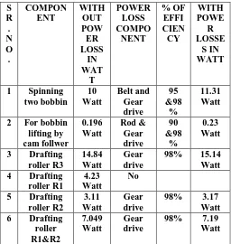
Fig D: Result block diagram for power distribution. TABULAR RESULT: S R . N O . COMPON ENT WITH OUT POW ER LOSS IN WAT T POWER LOSS COMPO NENT % OF EFFI CIEN CY WITH POWE R LOSSE S IN WATT
1 Spinning two bobbin 10 Watt Belt and Gear drive 95 &98 % 11.31 Watt
2 For bobbin lifting by cam follwer 0.196 Watt Rod & Gear drive 90 &98 % 0.23 Watt
3 Drafting roller R3
14.84 Watt
Gear drive
98% 15.14 Watt 4 Drafting
roller R1
4.23 Watt
No
5 Drafting roller R2
3.11 Watt
Gear drive
98% 3.17 Watt 6 Drafting
roller R1&R2 7.049 Watt Gear drive
98% 7.19 Watt
III.CONCLUSION
From the findings and shortcomings of the exhaustive literature study it is concluded that to improve the performance of workers the charkha machine need to redesign considering the ergonomic aspects. Further it is decided to reduce the weight and size in order to make it users friendly and cost effective.The power analysis is take place for the exact power consumption of the two spindle charkha existing machine. The proposed machine will improves the production with low weight and cost than the existing machine.
ACKNOWLEDGEMENT
I would like to thanks Dr. G. V. THAKRE Professor and Head of Department, MechanicalEngineering, B.D.C.E Sevagram, forhis guidance and valuable suggestions. I would thank to my college for providing valuable facilities which helps me in carrying outmy research work. I also express thanks to my parents, friendsand colleagues.
REFERENCES
[1] Dr.G. V. Thakre , “Assessment of factors affecting the productivity of amber charkha Ergonomics Evolution of workers.” et al. / International Journal of Engineering Science and Technology (IJEST), ISSN: 0975-5462, Vol. 3 No. 7871, 11 November 2011.
[2]R.Chattopadhyay, R.B.Chavan and R.K.Nayak ,“NMC Charkha: A Design Analysis’’ from Technological Considerations Department of Textile Technology Indian Institute of Technology, New Delhi 110 016, India.
[3] N. U. Alone, Prof. J. F. Agrawal, “Experimental Validation of best suitable mechanisms for manually powered Lilliput gin ”, International Engineering Journal For Research & Development
[4] Haidar F. AL-Qrimli, Karam S. Khali, Ahmed M. Abdelrhman, Roaad K. Mohammed A &Husam M. Hadi “A Review on a Straight Bevel Gear Made from Composite” .
[5] A. AthisayaSagayaRajan G. ShaikUsmansha “Optimization & Analysis of Forging Press Gear Box” March, 2014, Vol 3 Issue 3. [6] M.S. Navle, Dr. A. V. Damale “Weight Optimization of the Gear Train – AReview” Vol. 3, Special Issue 1, March 2016. [7] Andure M.W. , Jirapure S.C. , Dhamande L.P “Advance Automobile Material for Light Weight
Future – A Review” , International Conference on Benchmarks in Engineering Science and Technology ICBEST 2012.