Copyright to IJIRSET www.ijirset.com 710
ISSN (Online) : 2319 - 8753
ISSN (Print) : 2347 - 6710
I
nternationalJ
ournal ofI
nnovativeR
esearch inS
cience,E
ngineering andT
echnology An ISO 3297: 2007 Certified Organization, Volume 2, Special Issue 1, December 2013Proceedings of International Conference on Energy and Environment-2013 (ICEE 2013)
On 12th to 14th December Organized by
Department of Civil Engineering and Mechanical Engineering of Rajiv Gandhi Institute of Technology, Kottayam, Kerala, India
EFFECT OF VARIABLE GAS ORIFICE GEOMETRY ON
GAS-ON-LIQUID IMPINGING INJECTORS
Rakesh P.
Associate Professsor, Department of Mechanical Engineering, College of Engineering, Trivandrum, Kerala, 695016, India
ABSTRACT
Impinging jet injectors has often been a preferred con-figuration in liquid propellant rockets, the most common form of which is the Liquid-on-Liquid doublet. This config-uration provides numerous advantages that it can be pro-posed as an alternative to coaxial injectors for engines em-ploying gas-liquid propellants. Efforts to achieve this re-sults in Gas-on-Liquid impinging injectors employing iden-tical orifices. Nevertheless a problem identified with it tha t it could not give desired mass distribution for a given mass ratio (MR). This problem could be corrected by using vari-able gas orifices. In the present work the effect of employ-ing variable gas orifices is investigated. It has been found that at low MR the SMD (Sauter mean diameter) obtained by using variable gas orifices are comparable and at high MR the small orifice yields low SMD. For the MR used for cryogenic application the large orifice require only low pressure budget rendering it a suitable choice.
NOMENCLATURE
MSR Mass ratio (liquid to gas) SMD Sauter mean diameter
∗Address all correspondence to this author.
1.INTRODUCTION
Copyright to IJIRSET www.ijirset.com 711
also important that the basic mechanistic features of sprays from such injectors are to be understood before one looks into their performance as engine compo-nents. The present experimental work aims to resolve some of these issues.
The basic geometric and operational parameters of im-pinging injectors [2] are the diameter, length and inclina-tion of the orifices, inter-orifice distance which along with the inclination decides the pre-impingement development of the jets, the pressure drop across the orifices and the op-erating pressure and temperature conditions. While like-impinging configuration with identical conditions on the two jets provides symmetric impinging and the eventual spray characteristics, the unlike impinging is a little more complex even for liquid-on-liquid jets. One can expect the gas-on-liquid impinging to be still more complex because of large density differences and expansion of jets down-stream of the orifice.
Most of the published work on impinging injectors deal with liquid-on-liquid type of atomizers, although only a few among them deal with unlike media. Parametric stud-ies on such atomizers [3] have given insight on the extent of influence that different variables exert with respect to fina l spray features. The orifice diameter determines the jet di-ameter and the mass flow rate of the liquid for a given pres-sure drop. The influence of orifice on drop size is described in Douglass et al. [4] smaller the jet diameter, smaller the mean drop size. The orifice length to diameter ratio and the surface finish of the orifice have a role on the jet de-velopment. A progressive increase in the L/D tends to in-crease the losses by friction and hence to reduce the jet ve-locity, which in turn will have an effect of increasing drop size. It was found that [4] greater the impingement angle, greater the amount of propellant back-flow. In fact propel-lant back-flow is proportional to the cosine of the impinge-ment angle. The angular distribution and mixing unifor-mity also depends on the impingement angle [5]. The nor-mal component of momentum of liquid jet increases with an increase in impingement angle, which is expected to in-crease the quality of atomization. As mentioned earlier, the inter-orifice distance and the impingement angle will together decide the preimpingement length which when in-creased progressively is likely to introduce disturbance in the velocity profile of the liquid jet with free boundary, due to interaction with the surrounding gaseous medium. Fur-ther, it has been also found that mis-impingement of jets cause rotation of jets and affect mixing uniformity and drop size [6].
The reports available on gas-on-liquid configuration are scanty. One such study [3] has shown that the dominant factors for gas- liquid impingement which influence drop size are the injected momentum ratio of jets, the dynamic pressure of injected gas and orifice diameter ratio. For con-stant orifice diameter ratio increase in dynamic pressure decreases the spray diameter [3]. The effect of the ratio of liquid orifice to gas orifice as studied by Mehegan re-veals that for constant dynamic pressure it increases the spray drop size. The spray shaping effect of the variable gas orifice configuration has been shown to some extent by Douglass [4]. This configuration does not seem to have at-tracted much interest later although it appears to have cer-tain application potential as well as possess very interesting physics. The study by Rakesh et al. [7] revealed that normal gas mometum to liquid mass ratio as an important parame-ter in describing the spray at various operating conditions. However the study with equal sized injectors found spray deviation towards the wall at desired mass ratio to be a ma-jor problem. The present study therefore re-examines this by employing variable gas orifice size for a fixed liquid ori-fice which may solve the problem. The gas and liquid used in present study are air and water in proportions which sim-ulate the fuel and oxidizer components of the propellants in rockets. A limitation, however is that the typical Reynolds number and Weber number of jets encountered in actual rocket engines are higher than the ones experienced in the laboratory conditions.
2.EXPERIMENTAL DETAILS
Copyright to IJIRSET www.ijirset.com 712
impinging injectors. It consists of a two stage reciprocating compressor with an intercooler driven by a three phase 10 hp motor. The air from the compres-sor is stored in an air storage tank which is designed for air at pressure up to about 15 atm. From the air storage tank two air lines are taken, one of which is connected to a wa-ter storage tank of about 40 l capacity and the other end to the control board for the impinging injectors. The air line is then connected to the air injector on the left side of the injector plate through a valve and a pressure gauge. A wa-ter tapping is taken from the bottom of the water storage tank and is connected to a filter on the control board. The line from the water filter is then led to one of the injectors through a control valve and a pressure gauge.
Figure 2 shows the details of the injector used for the study. It consists of an injector body which is modular in design so that injectors of different diameters can be in serted with relative ease. The injector is smoothly con-verged so as to minimize pressure loss. The arrangement permits variations in orifice sizes, inter-orifice distance and the inclination of the jets. The orifice sizes in the present work range between 0.5 and 1.5 mm and the pressure drop up to 7 atm. Calibration runs have shown that typical ori-fice discharge coefficient was above the sharp edge value of 0.61 but rarely above 0.9. Under the operating con-ditions the liquid side Reynolds number works out to be around 30.000 and the Weber number about 10.000. These are lower than those encountered in rocket motors largely because of the orifice size limitations in the laboratory.
FIGURE 1. SCHEMATIC OF EXPERIMENTAL SETUP.
FIGURE 2. SCHEMATIC OF INJECTOR ASSEMBLY
Copyright to IJIRSET www.ijirset.com 713
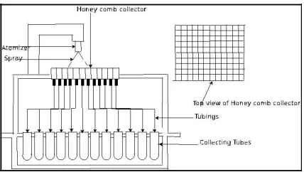
FIGURE 3. SCHEMATIC OF THE PATTERNATOR USED IN THE STUDY
The droplet size distribution was measured using Malvern Mastersizer X particle analyzer which works on the principle of diffraction of a laser beam in the presence of droplets in the spray. The instrument provides the line of sight averaged diffraction data. A large number of ex-periments are conducted to bring out the effect of variable gas orifice area on the Gas-on-Liquid impingement pro-cess. This includes oversizing and undersizing the gas ori-fice in relation to the liquid orifice.
3. RESULTS
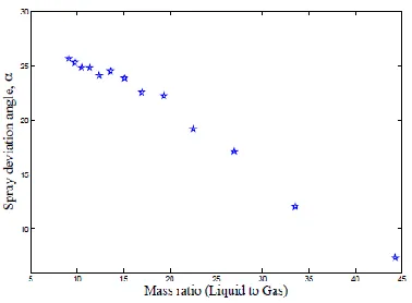
Experiments with equal orifice Gas-on-Liquid imping-ing injectors have revealed that for a required mass flow ra-tio it is difficult to obtain a desired mass distribution. Mor e-over as the gas pressure drop increases for a fixed liquid pressure drop the resulting spray mass get skewed to one side of the combustion chamber resulting in hotspots on the walls, thus resulting in combustion chamber damage. The study of the spray deviation angle reveals that it is very much depending on the momentum ratio (MR) of the jets. Since the density of gas is less than that of liquid, a very high pressure drop is required for the gas jet to achieve the same mass flow rate of liquid. Thus for the required mass ratio's in some applications the equal orificed impingement may give skewed spray distribution
A mass distribution study has been conducted for find-ing the spray mass concentration at different mass ratio's. The mechanical patternator mentioned earlier has been used for the purpose. Figure 5 shows the mass distribu-tion for various gas and liquid pressure drops. Inorder to study the effect of momentum ratio on the mass distribution
Copyright to IJIRSET www.ijirset.com 714
(b) Spray deviation angle variation with MSR
FIGURE 4. SPRAY DEVIATION ANGLE VARIATION WITH MSR
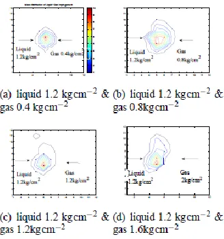
of Gas-on-Liquid impinging jets, test were carried out by keeping the pressure drop of water at 0.8 kg cm−2 and the air pressure drop varying from 0.4 kg cm−2 to 3.6 kg cm−2 thus changing MR from above unity to below unity.The re-sult of the mass distribution study is shown using contour plots which is suitable for any injector.
It was observed that initially the mass distribution is el-liptical and when the gas pressure drop is increased a dent is formed on the elliptical surface. This dent increases with MSR and after some MSR the dent size doesn't vary much. We can see from the above contour plots that the location of maximum mass region represented by the red region in the contour plot shifts with gas pressure drop and after a particular MSR it's position is mainly stagnant. It was ob-served that that as the MSR increases the spray major axis width increases.
Thus we have seen from the above plots that for re-quired mass ratio's of about 10, the spray mass distribution may not be a desired one.
FIGURE 5. EFFECT OF MASS RATIO ON THE MASS DISTRIBUTION OF GAS-ON-LIQUID
Copyright to IJIRSET www.ijirset.com 715
Thus in order to obtain the desired mass distribution experiments are done with vari-able gas orifices. The size of the gas orifice is varied from 0.5 to 1.5 mm.The pressure drop for gas nozzle was varied from 0.4 kg cm−2 to 4.8 kg cm−2 and that of liquid nozzle kept constant at 1.2 kg cm−2. Figure show the plot show-ing the effect of orifice diameter on SMD at various mass ratio's. The plot revealed that that SMD obtained with various gas orifices depends upon the MSR. As MSR increases the SMD in the case of large orifices increase rapidly be-cause most of the mass goes out without impinging the liquid jets. The gas jet issuing out of the orifice diverges rapidly ( divergence phenomenon varies depending upon the gas jet is subsonic or under expanded sonic). This divergence along with the large width cause most of the gas jet to pass without impinging the liquid jet. The large gas jet may also reduce the divergence of the spray. For a given MSR the small orifice gives a small SMD. This is beacuse for a small orice, to keep the same mass flow rate as that of large orifice, large dynamic pressure should be high. This dependance of the dynamic pressure on drop size has been verified by Mehegan.
FIGURE 6. EFFECT OF VARIABLE GAS ORIFICE ON SPRAY SMD
FIGURE 7. MASS DISTRIBUTION PLOTS FOR LIQUID DIAMETER 0.5mm& GAS ORIFICE
DIAMETER 1.2mm (a)LIQUID 1.2kg cm−2 & GAS 0.4kg cm−2, (b)LIQUID 1.2 kg cm−2 & GAS 0.8 kg cm−2, (c)LIQUID 1.2kg cm−2 & GAS 1.2kg cm−2, (d)LIQUID 1.2 kg cm−2 & GAS 1.6kg cm−2
Copyright to IJIRSET www.ijirset.com 716
liquid orifice diameter being 0 .5 mm.
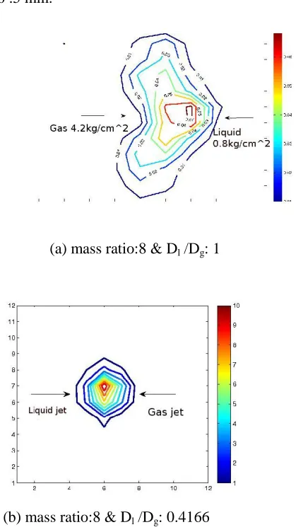
(a) mass ratio:8 & Dl /Dg: 1
(b) mass ratio:8 & Dl /Dg: 0.4166
FIGURE 8. MASS DISTRIBUTION AT VARIOUSDl/Dg(a)MSR:8 & Dl /Dg: 1, (b) MSR:8 & Dl /Dg:0.4166
Thus for the process of getting uniform distribution gas orifice diameters were changed for a constant liquid orifice diameter. It was found that as the gas injector diameter increases in relation to the liquid diameter more uniform distribution is obtained. As the gas diameter increases in relation to the liquid diameter, more gas mass flow rate is obtained at a less pressure drop. Thus more or less a ellip-tical mass distribution can be obtained at desired gas mass flow rate . Moreover for a particular liquid to gas orifice diameter as the gas pressure increases in relation to the liq-uid diameter the distribution becomes more non-uniform as confirmed from the mass distribution studies. The fol-lowing plot shows a comparison of the mass distribution obtained for equal orifice gas and variable gas orifice noz-zle for a mass ratio of 8. Thsu Fig. 8 and Fig. 6 confirm that using variable gas orifice geometry helps to achieve the desired spray characterictics.
4. CONCLUSION
Copyright to IJIRSET www.ijirset.com 717
injectors it is difficult to obtain desired mass dis-tribution for a given mass ratio as the gas jet needs more pressure drop for a given mass flow rate. The study with variable gas orifice injectors reveals that at in the range of mass flow ratio's used with cryogenic applications the de-pendance of SMD on gas orifice size is negligible. At high mass ratio's the small orifice gives better atomization whic h may be due to it's high dynamic pressure at same mass flow rate. The mass distribution plots with varisble gas orifice injectors confirms that desired mass desired mass distribu-tion can be obtained which makes it superior to the equal orifice configuration.
ACKNOWLEDGMENT
The author thank University Grants Commission of India for supporting the research under the UGC-CAS scheme. Thanks are also due to Prof. B.N. Raghunandan, I.I.Sc. Bangalore for his expert guidance on the subject.
REFERENCES
[1] Anderson, W., Ryan, H., Pal, S., , and Santoro, R. “Fundamental studies of impinging liquid jets”. AIAA Materials Specialist Conference-Coating Technology for Aerospace Systems.
[2] U.P.Kamath, 1998. “A comparative study of atom-ization characteristics of injectors in space propellant thrusters”. PhD Thesis, Indian Institute of science, Bangalore, India, june.
[3] Mehegan, P. F., Campbell, D. T., and Schenerman., C. H., 1970. Investigation of gas augmented injectors. NASA CR-72703 1, California, May.
[4] Douglass., H. W., 1976. Liquid Rocket Engine Injectors. Nasa space vehicle design criteria, nasa sp-8089, California.
[5] F.W.Hoehn, J.H.Rupe, and J.Sotter, 1971. Liquid-phase mixing of bipropellant doublets. Rept. TR 32- 1546 1, Jet Propulsion Lab, California Institute of
Technology, December.
[6] Gadgil, H. P., 2007. “Study on Impinging-Jet Atom-izers”. MS Thesis, Indian Institute of Science, Banga-lore, Karnataka, India, January.