ISSN(Online): 2319-8753 ISSN (Print) : 2347-6710
International Journal of Innovative Research in Science,
Engineering and Technology
(An ISO 3297: 2007 Certified Organization)
Vol. 5, Special Issue 13, October 2016
A Logistic Approach to Minimize the Train
Delay
Sudipto Basak1
Department of Information Technology, Kalyani Government Engineering College, Kalyani, West Bengal, India 1
ABSTRACT: Train is one of the most major transportation suites across the whole world. A major percent of civilization use railway for their journey day by day. As railway carries hundreds, thousands of people’s life in its track it should posses with full of safety. Congestion is increasing in railway day by day, so it should be on time, trying to minimize the delay as much as possible. Our paper mainly concern on train’s delay and taking an approach to minimize it. In this paper we mentioned some of the technologies that uses in Railway system besides we proposes our technical approach that uses traditional Bluetooth technology to cope up the above mentioned scenario. We also mention the limitations and possible remedies to overcome these by some assumptions.
KEYWORDS: Anti-Collision Device (ACD), Bluetooth, Railway Collision Avoidance System (RCAS), Ditressing, Audio Frequency Track Circuit (AFTS)
I. INTRODUCTION
Indian Railways is one of the biggest transportation systems in India that is continuing his journey for more than 150 years. Many technical improvements had been done so far to increase the safety, reliability and efficiency of the system. Our main concern of the current study is minimizing the train delay. Train delay has become an inherent part of this system and still shows its dominant effect in foggy winter. As the signal become almost invisible even from the closed range, drivers facing problem to propagate & reduce the train speed & this leads to a delay which also has an chain reaction effect. Here we provide an idea that help us to cope up with the situation & tries to minimize the delay as much as possible. We expect that Ditressing (checking the specified gap between two lines) should be done on regular basis. In future we also expect to give track related information to the driver as much as possible. In the next section of the paper we mainly discuss some related works, a problem statement, then we describe or proposed approach and ends up with conclusion with future scope.
II. RELATED WORKS
Lot of research had been done to improve the reliability and safeties for Railway system and we also expect that new technologies will evolve in future. Here we will discuss some of the well known related works that had been done so far and also helpful for our working purpose.
In [1] we get the idea of role of weather that causes disturbances on railway system. Bad weather directly or indirectly affects the train operator performances causing delays and cancellations of trains, net result loss of railway system. Snow, leaves, high temperatures and variations of temperatures put negative result in punctuality.
In [2] gives us the idea of the effect of weather or climate change on railway transport and infrastructure. It shows that snow, fog and rain accounts for a noticeable amount of accidents. In general we can say climate change likely causes an increase in heat-related disruption.
A new technology, Audio Frequency Track Circuit has been described in [3]. It mainly confirms the absence of train in a section of track. It also describes its failure in presence of breaks. At the end of the paper the author shows its proposed mechanism effectiveness with the help of PSpice simulation tools.
ISSN(Online): 2319-8753 ISSN (Print) : 2347-6710
International Journal of Innovative Research in Science,
Engineering and Technology
(An ISO 3297: 2007 Certified Organization)
Vol. 5, Special Issue 13, October 2016
The author represents a new approach for track-train data transmission for automatic rain control in [5]. It mainly focuses on the safety and reliability in which sample coding scheme have been verified by experiment in which injecting of audio-frequency Gaussian noise into a practical train circuit have been performed.
In [6] the author describes a new application that uses synchronizable error-control coding for detects trains with track-train data transmission with audio frequency track circuits. A new FSK modulated coding format is used in which a fixed duration-message telegram is transmitted. Data’s are encoded by conventional Hamming codes which includes error control-bits and with a final parity check.
Currently running and adopting new technologies, famously known as Anti collision Device (ACD) and Railway Collision Avoidance System (RCAS). ACD is invented and used by Indian Railway System. It mainly work with the help of GPS satellite with device installed in the Loco and mainly focuses to prevent head-on rear-end and side collision etc. It also provides information on unmanned level crossing. But ACD have several disadvantages over its advantages. It not depends on Railway’s signaling system and GPS’s performance in India is still arises some question and its accuracy is quite less than accurate ACD is still not full proof. A new version of ACD known as TCAS is on the development stage. It seems to have more centralized system than ACD and have a deep coupling with Railway’s signaling system.
Problem Statement regarding curvature on train track:-
Given a curvature in terms of (x, y, z) we are estimating (r, )
Solution:
Figure 1
Here OB = r (radius of the circle)
CX = y; AB = z; ACB = x (curvature of the circle) <AOB = (angle of curvature)
( − ) +( ) =
( ) = -( − )
( ) = y.(2r–y)
(2r−y) = ( ) .( )
r = ( ) .( )
Now we have to calculate x (as given in the picture)
X=2πr*( )
= π
=
π.(( ) .( ) )
III. PROPOSED METHOD
ISSN(Online): 2319-8753 ISSN (Print) : 2347-6710
International Journal of Innovative Research in Science,
Engineering and Technology
(An ISO 3297: 2007 Certified Organization)
Vol. 5, Special Issue 13, October 2016
To do this we mainly plant Bluetooth devices beside the track to propagate signal information. There will be few Bluetooth devices (no. will vary s per requirement) apart from each other by specific distance (depending on their range). We mainly use Bluetooth devices because it can send signal in all directional. It has low cost as compared to sensor’s which are unidirectional. Using sensor’s we can only send signal to a straight line and we would need more sensors to cover a curve area/track. To cover a curve track we would have to fit sensors according to the signal direction (tangent to the curve). This scenario can be easily solved by much fewer no of Bluetooth devices as compared to sensors. Also by taking any two points on the curve & calculating their distance we can calculate the curvature radius & angle. In eq. (i) & (ii) we show how we can estimate these values. Using both eq. we can also optimize the plantation of Bluetooth devices (For a curve path we can cover more distance in terms of curve path that is more than straight path for a given Bluetooth coverage radius). Thus it can help us to minimize the delay due to invisibility of signal. In Figure 2 we show the overall setup of our approach.
Figure 2
Besides planting Bluetooth device we have to consider its real life application also. So we have to be aware all types of shortcoming of this scheme and at the same time providing a solution for the same. In the following section in our paper we have to make few assumptions that should be taken into account along with our proposed scheme.
ISSN(Online): 2319-8753 ISSN (Print) : 2347-6710
International Journal of Innovative Research in Science,
Engineering and Technology
(An ISO 3297: 2007 Certified Organization)
Vol. 5, Special Issue 13, October 2016
IV. ASSUMPTIONS
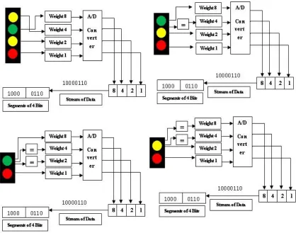
Assumption 1: Detection of signal by a loco for its own track among several tracks as there is normally more than 1 track & every track is installed with Bluetooth devices.
We mainly use pairing/token technology like our conventional mobile phone that will be different for each track. Each track has its own pairing. So when a loco receives more than one signal it only accepts to which it’s pairing matches & discards other signal information (See Figure 3). Thus the loco can propagate with right information.
Figure 3
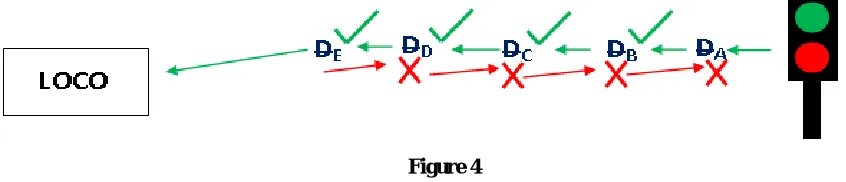
Assumption 2: Let there are 5 (usually will exist more in real life application) Bluetooth devices A, B, C, D, E where A is the nearest & E is the farthest from any approaching signal post. Now B sends information to C but due to Omni-directional property vice-versa will happen & violating our principle.
Besides paring, we also use ID to each & every Bluetooth devices. We will fixed the ID in decreasing order (for ex. A is the highest, E is the lowest). Now any Bluetooth devices can receive at most two signals from its neighbors (other track Bluetooth devices’ signal will be discarded due to unmatched pairing/tokens) it will only receive the information from the largest ID & discard the other (See Figure 4). Thus solve the problem.
Figure 4
Assumption 3: Not planting of Bluetooth devices all along the track, if not necessary.
ISSN(Online): 2319-8753 ISSN (Print) : 2347-6710
International Journal of Innovative Research in Science,
Engineering and Technology
(An ISO 3297: 2007 Certified Organization)
Vol. 5, Special Issue 13, October 2016
station & we know after getting the Home signal driver can guess what will be the Starter signal (See Figure 5). For example If the train has a predefined stoppage at any particular station, whatever be the Starter signal it will stop after getting a ‘proceed’ information from the Home signal.
Figure 5
Assumption 4: Reflection of updated ID to the loco when the loco when the loco runs on one track & switches to another track after sometime.
First of all we start planting devices only where the trains are allowed to speed up. For any junction station, where too many crossing are provided (trains usually propagate slowly in these type of junction), we will not plant Bluetooth devices. Although Bluetooth devices provide Home signal information must be there & when the crossing are minimized by a certain level then we again apply our usual policy. We mainly fix a device underneath the loco’s surface. After every ‘Point’ where there is a chance to change track we will plant the device between the two lines of the track, obviously after the point facing forward direction. This device will act as an ID changer. This will update the ID of the device situated in the loco’s cabin of the respective track. We can say it is one type of photocopy procedure (See Figure 6).
Figure 6
Assumption 5: We have stated that we will use different ID’s for different track, ID changer will update the latest ID whenever track changes occur or not. In real life application, we see any particular track is used for both ups & down. We have to distinguish between them & make proper guide the system.
ISSN(Online): 2319-8753 ISSN (Print) : 2347-6710
International Journal of Innovative Research in Science,
Engineering and Technology
(An ISO 3297: 2007 Certified Organization)
Vol. 5, Special Issue 13, October 2016
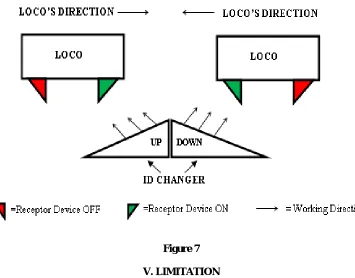
update. For this problem, we will perform a little bit of modification to our principle. ID changer will look like a slope that have a particular direction as well as the receptor (which is just vertically rotated) fitted under the loco (See Figure 7). So it will update only one value instead of two. Obviously one of these two values will work for upward & one for downward direction. Now a little performance we will expect from driver’s end. When he stars the loco to run he must have to turn on the ‘Virtual Eye’ situated in its cabin according to its direction of propagation and also have to turn off the receptor device of other end (otherwise it will take both values and make disaster). Obviously an ID used for upward direction should matches with the Bluetooth devices facing forward. Otherwise problem will occur. One word we can say that ID changer consist two different ID’s should be installed on those track which acts for both purpose. A track work as unidirectional can be suited with ID changer having one ID, as there is no need for two different ID’s and also no need to plant two ID Changer devices.
Figure 7 V. LIMITATION
At end we can say that this proposed approach is purely theatrical and not tested in real time environment. It should be tested in real life to check its faulty, limitation etc and we have to check how its cop up in real time system also.
VI. ACKNOWLEDGEMENT
I would like to thank Dr. Malay Bhattarcharya, Assistant Professor of Indian Institute of Engineering, Science and Technology, Shibpur and Mr. Md. Iqbal Quarishi, Assistant Professor of Kalyani Government Engineering College, Kalyani for their moral support and suggestion.
VII. CONCLUSION AND FUTURE SCOPE
ISSN(Online): 2319-8753 ISSN (Print) : 2347-6710
International Journal of Innovative Research in Science,
Engineering and Technology
(An ISO 3297: 2007 Certified Organization)
Vol. 5, Special Issue 13, October 2016
fractures, broken parts etc beside signal information. Hope we will come up with better solution to solve those problems. Continuous modification of these schemes is also expected.
REFERENCES
[1] Yuanni Xia, Jos N. Van Ommeren, Piet Rietveld Willem Verhagen “Railway infrastructure disturbances and train operator performance: The role of weather”, Transportation Research Part D 18 (2013) 97–102.
[2] Mark J. Koetse *, Piet Rietveld, “The impact of climate change and weather on transport: An overview of empirical findings”, Transportation Research Part D 14 (2009) 205–221.
[3] C. Gautham Ram, A. Nithya, V. Jayashankar, P. R. Goundan, “Fail Safe Operation of Audio Frequency Track Circuits for Railway Signaling” , India Conference (INDICON), 2009 Annual IEEE, Pages: 1-5.
[4] R.J. Hili, D.N. Weedon, “Synchronizable error-control coding for railway track circuit data transmission”, Vehicular Technology Conference, 1987. 37th IEEE, Pages: 206-213.
[5] R.J. Hili, D.N. Weedon, “Safety and Reliability of Synchronizable digital coding in railway track-circuits”, Reliability, IEEE Transaction, and Vol: 39, Issue 5, Pages: 581-591.