Limitations of the Load Time Function Approach
for Assessment of Complex Structures
Alexander Iliev1, Anton Andonov2, Marin Kostov3
1 Specialist, Risk Engineering Ltd., Sofia, Bulgaria 2 Chief Expert, Risk Engineering Ltd., Sofia, Bulgaria
3 Professor, Dept. of Earthquake Engineering, Bulgarian Academy of Sciences, Bulgaria
ABSTRACT
The classical approach for analyses of effects on nuclear structures due to aircraft impact is requiring definition of a load time function (LTF) that is consequently applied on the target. This chain of analyses poses a lot of benefits and has been well proved in the past for impacts of small and military aircrafts on rigid walls. The recent challenges for detailed analysis of large passenger aircraft crash on complex nuclear structures require careful reconsideration of some of the steps.
In this paper we consider some effects that the complexity of the target geometry may cause and change the usual LTF definition for impact on a flat rigid wall. We consider two types of rigid barriers – offset plane walls and cylindrical walls. In both cases the impact is more complex and the form of the LTF is changed. The engines of the aircraft that are usually an important element of the penetration analyses are showing significantly different load pattern.
Despite the large model uncertainties of a complex missile-target interaction, it may lead to better and more realistic assessment of the loads due to large aircraft impact on complex structure.
INTRODUCTION
Airplane impact on nuclear power plants (NPP) is an important safety issue. It is considered, that the starting point, was the request of the US National Regulatory Commission (NRC) in 1968 for safety evaluation of the Three-Mile Island NPP against accidental aircraft impact, Riera (1980). As part of this assessment, Riera (1968) has developed a method for calculation of the load time function (LTF) of an airplane impact on a rigid target. This model is considered as a pioneering study of aircraft impact problem and is still widely used today. In this method, the impact force time history is first determined based on the aircraft crushing strength information and impulse conservation principles, assuming that the target is rigid. The obtained force time-history is then applied to a finite element model of the structure in a time history analysis. Consequently, the structural capacity is evaluated, based on the internal forces and the associated stresses of the computed response.
With the development of computer hardware, the computational analyses based on Finite Element Method (FEM) are becoming more and more sophisticated. In the last 10 years, significant progress has been made of explicit missile-target interaction analysis. In this method, a combined dynamic analysis model of both the missile and target is developed, and the dynamic response is determined as an initial velocity problem. The nonlinear models are typically significantly larger and more complex than those used for the force time-history analysis method. The advantage of this method is that the airplane is represented very realistically as multi degree of freedom system, which provides significant potential for more accurate results. The complex missile-target interaction can be used for a direct analysis of the impacted target or to define a load time function based on impact at rigid wall. In both cases significant uncertainties are present, first due to the computational methods and secondly due to the inherent uncertainty of impact initial conditions (mass, speed), Kostov et al (2013).
“Methodology for Performing Aircraft Impact Assessments for New Plant Designs”. IAEA (2012) has prepared a draft of “Safety Assessment of NPP Structures against Human Induced External Events”. Both documents discuss the safety assessment of NPP subjected to airplane impact. Certain guidelines and recommendations on the application of the loading by use of load-time function and by direct simulation of missile impact are presented.
This paper aim to discuss part of the main concepts of the LTF definition and the application in case of complex irregular structures. In some cases the straightforward application of the LTF approach may lead to erroneous
conclusions
.SCOPE OF THE PROBLEM
The classical approaches for impact analyses imply that a LTF is determined based on the aircraft crushing strength information and impulse conservation principles, assuming that the target is plane and rigid. In reality, majority of the containments of the NPPs in operation use cylindrical shells with a dome at the top. Current practice is to derive the LTF of an airplane on a planar rigid wall and then to apply it to the cylindrical shell or the dome of the containment.
There are few sources that give guidelines how to apply the load time function to the target. According to NEI (2011) "The aircraft and engine are assumed to strike perpendicular to the centerline of the structure, thereby subjecting the structure to the maximum force of the aircraft. Because the containment is curved, missing the centerline reduces impact forces".
Another issue is that the airplane may break up into pieces, each of which may become a separate missile with its own trajectory, IAEA (2012). IAEA (2012) suggests that an analysis of the missiles that could be produced and their significance should be made on the basis of engineering judgment, with due regard for the possibility of simultaneous impacts on separate redundant systems.
This paper aims to present cases when due to complex irregular structures, the application of a LTF concept is difficult and should be carefully planned and prepared
.
MISSILE MODEL
Detailed impact simulation of an airplane requires finite element code with explicit time integration and nonlinear capabilities. LS-DYNA is a general-purpose finite element program, suitable for such calculations. It is one of the few finite element programs capable to analyze large deformation dynamic response of three- dimensional inelastic solids and structures including damage and failure. The program contains substantial material library and complex three-dimensional contact-impact algorithm which meet exactly the requirements of the current study.
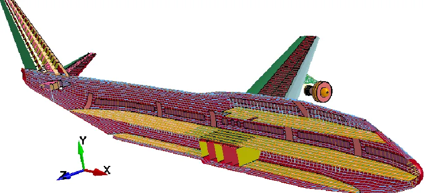
The finite element model of Boeing 747-400 airplane used in the presented analyses is based on REL (2009). Since airplanes are extremely complex structures, for the need of our study, some simplification are done and secondary components of the airplane are not presented in the finite element model. The main components of the missile that are represented in the finite element model are:
Fuselage with frames and stringers;
Two passengers and one luggage deck;
Centroplan with ribs and stringers;
Engines with fixation at wings;
Horizontal and vertical stabilizers with ribs and stringers.
Components of the airplane that have dimensions of the cross section significantly smaller compared to their length as stringer, frames and deck girders are modelled with beam elements. Plane components of the airplane as the skin of the fuselage and ribs in the wings and the stabilizers are modelled with shell elements. At places with concentration of stringers, such as the wings and the stabilizers, mesh is refined in such manner that connectivity between the components is assured.
Belytschko-Tsay formulation is used for all shell elements and Hughes-Liu with cross section integration for all beam elements. The finite element model consists of 39357 beam elements and 53929 shell elements connected with 48306 nodes.
The fuel of the airplane is modelled with variation of mass density at the specific locations of the reservoirs. The airplane is assumed to be fully loaded and Maximum Take-off Weight (MTOW) from 394t is used. View of Boeing-747 finite element model is shown at Figure 2.
NON PLANAR TARGET MODEL
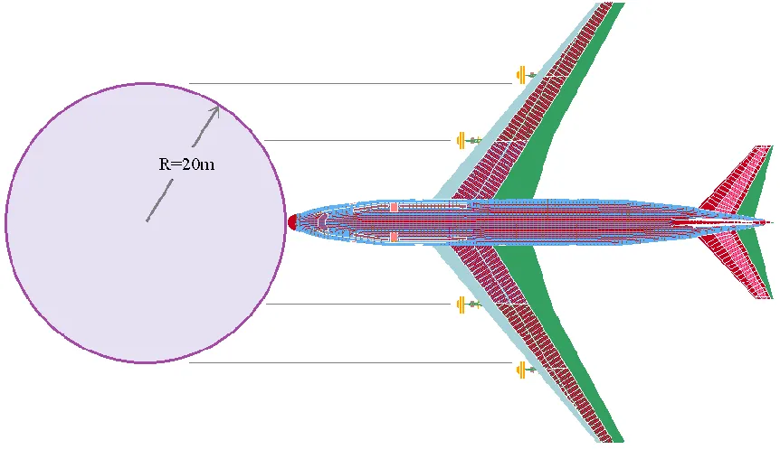
In case of target structures with complex geometry, the application of a predefined load-time function may be difficult. An example of such case is presented at Figure. 1, where the outer parts of the auxiliary building will prevent a plane to approach the containment, i.e. the outer structure may slice the wings of the airplane and change the trajectory of the missile. Is it appropriate to apply a load-time function, derived from a single planar rigid wall, by projecting the stamp of the missile to the expected impact locations? To verify such kind of application, the following analyses were performed.
Two different setups of the rigid wall are being compared. In the first case, the rigid wall is being divided into three parts, RW-1, RW-2 and RW-3. In this case the three parts of the rigid wall are being aligned at one line, therefore resulting to Riera's classical prerequisites. At the second case RW-1 and RW-3 are shifted at 20m ahead, therefore simulating the NPP layout at Figure.1. This setup of the rigid wall will be named “offset wall”.
Figure 3. Different setup of a rigid wall.
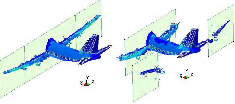
Figure 4 shows the impact simulation at time 0.3 seconds. It can be seen that in case of an “offset” rigid walls, the wings are sliced along with the external engines.
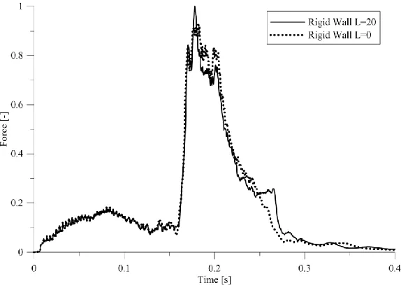
Reaction history of RW-1 and RW-3 are shown in Figure 5. It can be seen that the reaction history in case of “offset wall” is higher. This is caused by the fact that the external engines along with the associated part of the wings crush with higher velocity than in the “planar” rigid wall setup. This shows that if we apply a load-time function, derived for plane rigid wall, by simply projecting it to the impact location, we will underestimate the maximum impact force from the external engines by 40%. This shall be taken into account if safety related equipment is situated in such auxiliary structures surrounding the containment.
Figure 5. Load-Time Function derived for RW-1 and RW-3 for different setup of the rigid wall
Although the difference in the reaction force for RW-1 and RW-3 is considerable, the reaction histories for RW-2 tend to be from the same order. Considering the high level of uncertainties inherent for such complex missile-target interaction analyses, it seems to be practical to use load time function derived for classical setup of the rigid wall- aligned at one line. However, these conclusions are valid for the geometry of the current case study. For cases where the distance between the offset walls is smaller, the force reduction in RW-2 (main target) can be higher.
CYLINDRICAL TARGETS
An essential component of the nuclear power plant is the containment structure. The containment has to prevent the reactor installation from external impacts as well as to provide a tight physical barrier against release of radioactive materials in case of severe internal accidents. Common practice for containment structures is to use cylindrical shells in height with dome at the top. Most of the NPPs in operation have containment with radius between 15m and 25m, depending on the position of the steam generators (vertical or horizontal). For the current study we have investigated two cylinders, one with radius of 20m (Figure 6), which represent most of the containment in operation and one with radius of 50m to take an idea of the influence if the cylinder's curvature. It should be pointed out that the distance between the two external engines for Boeing 747-400 is approximately 43m.
The aircraft is assumed to strike perpendicular to the centerline of the structure, thereby subjecting the structure to the maximum force of the aircraft. This is not going to be the case for the maximum impact force of the engines as they obviously will be decelerated due to crushing of the nose and a portion of the fuselage, i.e. engine impact force that is applicable for penetration analysis could be underestimated.
Figure 6. Airplane impact at cylindrical shell with radius 20m
internal engines impact the cylinder at approximately 45 degrees, which is followed by stave off of the engines, observed at Figure 8. The external engines are observed to break off the wings at t=0.4s and since the distance between them is larger than the diameter of the cylinder, an impact was not realized. It should be mentioned that the peaks associated with the impacts of the engines are associated with much smaller impact area, i.e. much higher impact pressure, when the load time function is applied to the target building through a decoupled analysis. Therefore, despite that the peak impact force varies in about 5-10%, the use of a load-time function derived for a flat wall applied in decoupled analysis on a cylindrical containment will yield to conservative results. Having in mind this conservatism and the high computational effort for missile target interaction, it seems to be practical to use the “classical” load time function in aircraft impact analyses, especially for preliminary assessment.
Figure 7. Load-Time Function for different geometry of the target
CONCLUSION
The loads due to large aircraft impact on rigid targets with complex geometry setups are showing considerable different load pattern in comparison to LTF on rigid flat walls. Current findings show that in cases of a complex geometry of the target structure a careful evaluation of the predefined load time function should be performed. Special attention should be paid on different deceleration of airplane parts and their equivalent load forces.
In cases of cylindrical structures with relatively small diameter (in comparison to the airplane wing spread), the impact of the engines should be investigated separately. Applying a LTF derived for planar wall to a cylinder will lead to more conservative results, especially for the zones affected by the engines. In such cases complex missile target analysis shall provide more accurate results, but requires more complicate models and higher computational costs.
When auxiliary structures are surrounding the reactor containment the access of a large plane for direct impact could be difficult or impossible. In such cases, the impact load on the main target, i.e. containment, will be reduced due to initial destruction of part of the airplane in the surrounding auxiliary structures. For the case study presented herein, this reduction was found to be insignificant in comparison to the uncertainty embedded in such kind of analyses. On the other side, parts of the missile that may affect buildings surrounding the containment should have higher impact velocities, i.e. higher penetration potential. This shall be taken into account if important equipment is situated in such surrounding auxiliary buildings.
ACKNOWLEDGMENT
These analyses are partially supported by a research grant of the European Commission, research project RiskProtecCI, HOME/2010/CIPS/AG/045.
REFERENCES
Riera, J. D. (1980). “A critical reapraisal of nuclear power plant safety against accidental aircraft impact”,
Nuclear Engineering and Design, vol.57, 193-206.
Riera, J. D. (1968). “On the stress analysis of structures subjected to aircraft impact forces”, Nuclear
Engineering and Design, vol.8, 415-426.
Kostov, M., Iliev. A, Andonov, A. (2013). “Load Time Function definition for large commercial aircraft impact: Parametric Study”, Structural Mechanics in Reactor Technology (SMiRT22), San Francisco, USA.
(2009) “Assessment of Impact Load Curve of Boeing 747-400“, Risk Engineering Ltd (REL), Sofia, Bulgaria.
(2011). “Methodology for Performing Aircraft Impact Assessments for New Plant Designs”, Nuclear Energy Institute (NEI).