Leak Before Break Procedure for SFR Reactors and HTR Reactors –
Improvements and Validation
Hubert Deschanels1), Cécile Krakowiak2), Yann Kayser3), Jan Patrice Simoneau1) and Jean Luc Berton2)
1) AREVA NP– 10-12 Rue J. Récamier 69456 LYON Cedex 06 FRANCE
2) Commissariat à l'Energie Atomique CEN CADARACHE 13108 ST PAUL LEZ DURANCE Cedex France 3) Commissariat à l'Energie Atomique CEN SACLAY 91191 GIF sur YVETTE Cedex FRANCE
ABSTRACT
A large cooperative program involving CEA, EdF and AREVA NP has been conducted in France, in the field of Research and Development for Fast Reactors and more recently for High Temperature Reactors (ANTARES program), in order to make progress in LBB analyses. Experimental work was carried out by CEA.
The paper presents the improvements on the methodology and the main results that contribute to extend and validate some aspects of Appendix A16 LBB procedure.
For HTRs, pressurized helium is favourable for a reliable LBB demonstration. A detectable leak rate is expected even though the Crack Opening Area is low. Relevant helium leak models and the experimental validations are in progress.
For the SFR's conditions, the application of LBB procedure leads to conservative results, and a good correlation with experimental results is generally observed. The crack shape after wall penetration has been found conservatively evaluated, either under fatigue or creep fatigue conditions.
In a nutshell, further experimental work is necessary to adapt and consolidate the methodology for potential ANTARES applications (HTRs) and to limit overestimations of the size of expected detectable cracks (HTRs and SFRs). This paper also discusses improvements that would be needed for potential applications in the near future.
1. INTRODUCTION
The concept of Leak-Before-Break (LBB) is aimed to demonstrate that leakage of an appropriate gas or fluid through an hypothetical crack can be detected well before the crack could attain conditions of instability.
For more than ten years a large cooperative program has been conducted in France by CEA, EdF and AREVA-NP in order to develop defect-assessment-procedures and LBB methods. As a result, extension and validation of the RCC-MR appendix A16 LBB procedure have been carried out [1].
2. RCC-MR APPENDIX A16 LBB PROCEDURE
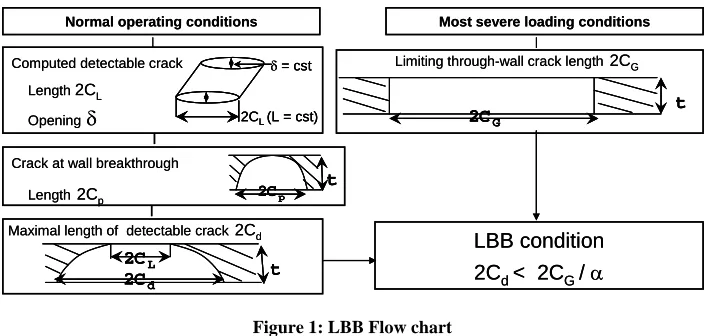
From Figure 1, it can be seen the overall scheme of the procedure [1] and [2].
Normal operating conditions
Computed detectable crack
Length2CL
Opening
δ
Most severe loading conditions
Limiting through-wall crack length2CG
Crack at wall breakthrough
Length2Cp 2Cp
t
Maximal length of detectable crack2Cd
LBB condition
2C
d< 2C
G/
α
2CG t
2CL
2Cd t
δ = cst
2CL (L = cst)
Normal operating conditions
Computed detectable crack
Length2CL
Opening
δ
Most severe loading conditions
Limiting through-wall crack length2CG
Crack at wall breakthrough
Length2Cp 2Cp
t 2Cp
t
Maximal length of detectable crack2Cd
LBB condition
2C
d< 2C
G/
α
2CG t
2CG t
2CL
2Cd t
2CL
2Cd t
δ = cst
2CL (L = cst)
δ = cst
2CL (L = cst)
Figure 1: LBB Flow chart
The lengths used in the LBB procedure are related to the dimensions of the detectable crack or that of the critical crack, as shown in Figure 2. The LBB condition is expressed by: 2Cd < 2CG / α , where the advised value for α is 2, the length 2Cd is the maximal dimension of the detectable crack, and 2CG is the limiting crack length.
2ci (initial crack)
2cp (At wall breakthrough) 2cd (Detectable through-wall crack; maximal length) 2cG (Limiting crack length; Length of critical through-wall-crack)
t
2cL (Detectable through-wall crack; minimal length)
Figure 2: LBB Verification
Evaluation of the Crack Opening Profile (COP) for leak area with complex crack shape is in progress [3].Current solutions are poorly adapted to thick structures and complex-shaped cracks, e.g. through-wall semi-elliptical cracks where the crack length is largely greater on one surface than on the other. Such feature appears to be characteristic of expected detectable defects in HTR or in SFR components. Main features of on-going works and recent improvements are described by Section 5.5.
3 BRIEF REVIEW OF AVAILABLE LBB METHODS
Most of the LBB applications are relative to piping systems and are based on the NUREG 1061 methodology [4]. This component seems to be suitable for the verification of the LBB approach. For instance, pipes are usually made of ductile material and the service conditions induce global bending moment load type. These features are favourable to the applicability of the LBB.
The LWR and the High Temperature Reactor HTR (see § 4.3) service conditions are characterised by high pressure.
On the contrary, SFR conditions are under low pressure and thermal gradient through the wall thickness. HTR components are also submitted to thermal radial gradients.
Main LBB procedures are briefly described below:
- Light Water Reactor LWRs approaches
NUREG 1061[4] was written for piping systems. It is a “global approach” type, rectangular through wall crack is assumed and safety margins are prescribed.Reference [5] discusses methodologies used in European (EU) countries. The German and UK LBB methodologies (R6 [6], BS [7]) are of the “detailed approach” type. However “global approach” procedure is suggested at design stage [6] and [7] and no stringent safety factors are prescribed.
- Sodium Fast Reactor SFRs approaches
• The DCRC report 13 procedure [8] was set up for the main vessel of the Fast Breeder Reactor.
• The RCC-MR-Appendix A16 ones [1] was written for vessel and piping systems.
• The JAPC procedure [9] and [10] deals with piping systems. Margin coefficient on leak rate is 2 instead of 10 for EU procedures.
The SFR procedures are of the “detailed approach” type. This feature of the methodology is based on the rules previously proposed in the framework of the former EFR project [8] and leads to a maximization of the detectable crack length 2Cd.
4. LBB APPLICATIONS
4.1 General Description
The structures considered here are designed and manufactured as high quality classed components including non destructive examination and operating conditions are monitored. Generally speaking, any significant degradation mechanism is prevented by the design provisions and In Service Inspection should allow for detecting it. However, hypothetical through wall crack is assumed, one aim of the LBB approach is to check the adequate mitigations of consequences.
There is no real past experience in the verification of the applicability of the LBB approach to thick vessels. Some of the unfavourable specificities have been pointed out [11]. Section 4.3 deals with pressurized vessels (thick vessels) as the applications for pipings and for thin vessels are described by Section 4.2.
4.2 Applications for SFRs
The LBB concept was used for the Main Vessel (MV) and pipings of the SPX ([12] to [14]) and PHENIX plants. As far as the MV is concerned, the LBB approach has been applied to verify the absence of risk as regards the core supporting function and to help in the definition of the In-Service Inspection (ISI) program. Generally speaking, the low level of membrane primary stresses, which is favourable for the integrity of the vessel, makes the application of LBB more difficult due to small crack opening areas.
4.3 Applications for HTRs
Two concepts of high temperature reactors are developed by AREVA NP in the frame of the ANTARES program. Both are provided with a so-called Pressure Boundary, comprising several connected vessels and enveloping the Nuclear Heat Source (NHS) and the Primary Heat Transfer System. The NHS would be largely common to both projects. The pressure of the Helium Primary coolant is about 50 to 70 bars depending on core inlet temperature.
Thick wall vessel is unfavourable to LBB [11]. However, the following points are in favour of LBB arguments for the ANTARES concepts:
- leak conditions are under pressurized helium,
- the 9Cr1Mo (candidate material) exhibits high fracture toughness and tearing modulus. As a result, a large limiting crack length is expected. In addition, the low Paris law exponent m, which is lower than 2, leads to smaller crack length at breakthrough than that provided by the standard master curve one (m~4).
5 RECENT AND ONGOING PROGRAM FOR HTR APPLICATIONS
5.1 Reliable Leak-rate through a Crack
Depending on the loading conditions, some potential cracks could be partially opened or almost closed. Thus, blocking effects may occur with liquid (e.g., water or sodium), leading to uncertain detection. In contrast, pressurized helium leak is more certain. This means that significant leak-rate through a potential Through Wall Crack (TWC) is expected despite the fact that the crack opening is very small for short cracks (cf. § 5.3).
5.2 Leak Detection
An on-line primary helium leak detection system could be based on the spectrometry technique which exhibits high sensitivity. This technique allows detection of very low content of helium (as low as 0.1 ppm). In case of leakage, the concentration is expected to be significantly higher than 100 ppm and higher than the background noises. In nominal operating conditions, very small crack size leads to exceed this concentration. Nevertheless, during normal operation, helium coming from sources other than the primary circuit should be in the atmosphere surrounding the Pressure Boundary: such a leak rate has been called Qdim. This could degrade the capability to detect very small leakages of the Pressure Boundary. The minimal detectable leak rate, Qmin, has to be as low as possible but above Qdim.Preliminary estimation of Qmin accounting for uncertainties leads to 0,5 Nm
3
/h. A thoroughly updated estimation should be conducted taking into account actual data relevant for the final design.
5.3 Leak Rate Calculation
In narrow channels, such as cracks, the validity of Navier-Stokes equations is linked to the ratio of the mean free path λ of the fluid molecules over the characteristic distance of the channel L, called the Knudsen number (Kn), and according to literature, those equations are valid for Kn < 10-3 (empirical limit). As an example, for a crack opening greater than 10 µm, helium pressure 71 bar and helium temperature 450°C, the Knudsen number is less than 10-3. It is therefore possible to use a classical method for hydraulic computations even though the crack opening is limited.
In order to illustrate the different flow regimes, leak models [15] have been investigated under different assumptions: laminar compressible isothermal (viscous friction bases either on the inlet or the outlet viscosity), turbulent adiabatic (with or without singular pressure losses). Furthermore, for large openings, the gas velocity is blocked by the nozzling effect (sonic flow). For small openings where friction dominates, a sonic model leads to largely overestimated leak rates as compared with isothermal and adiabatic models which are much close to each other, but for large openings, friction becomes negligible and the sonic model is applied.
δ (CMOD)= cst
L = cst Laminar
Turbulent
Sonic
Flow rate (kg/s)
1.E-09 1.E-07 1.E-05 1.E-03 1.E-01 1.E+01 1.E+03 1.E+05
10 100 1000 10000
δ
(µm)
Fl o w r a te (k g/ s )laminar (µ inlet) laminar (µ outlet) Sonic blockage turbulent - ρ average Star-cd
turbulent - friction only
Sonic model
δ (CMOD)= cst
L = cst Laminar
Turbulent
Sonic
Flow rate (kg/s)
1.E-09 1.E-07 1.E-05 1.E-03 1.E-01 1.E+01 1.E+03 1.E+05
10 100 1000 10000
δ
(µm)
Fl o w r a te (k g/ s )laminar (µ inlet) laminar (µ outlet) Sonic blockage turbulent - ρ average Star-cd
turbulent - friction only
δ (CMOD)= cst
L = cst
δ (CMOD)= cst
L = cst Laminar
Turbulent
Sonic
Flow rate (kg/s)
1.E-09 1.E-07 1.E-05 1.E-03 1.E-01 1.E+01 1.E+03 1.E+05
10 100 1000 10000
δ
(µm)
Fl o w r a te (k g/ s )laminar (µ inlet) laminar (µ outlet) Sonic blockage turbulent - ρ average Star-cd
turbulent - friction only
Sonic model
Figure 3: Helium Leak Rate Computation
Figure 3 presents the flow rate versus the crack opening for the different assumptions. Laminar regime could be significant for short cracks (small crack opening), turbulent regime should happen for crack openings in the range 80 µm to about 1 mm, after that nozzling would happen for greater crack openings. The retained values of the leak flow rate should be the minimum of the curves bundle.
Furthermore, the flow rate has also been calculated by the Star-CD CFD tool. This general purpose commercial code solves the Navier-Stokes and energy equations using a finite volume approach. The values obtained (square symbols) are quite close to the analytical formulations. Hence, the use of a finite volume formulation allows taking into account the actual COP, to get new margins.
If we take into account the COP through the wall thickness, for the case where the minimal value (inner skin) of hydraulic diameter crack is 25 µm (laminar region), the leak rate calculated by the Star-CD CFD code is found to be ten times higher than the one obtained by assuming cylindrical COP with the minimal Crack Mouth Opening Displacement (CMOD) through the wall. In addition, a greater leak rate is expected accounting for the actual COP instead of assuming a rectangular through wall crack shape. For a diverging COP, the leak rate should be 1/3 above that of the converging COP.
In a nutshell, the leak rate is highly dependent on assumptions made for the COP. Generally speaking, simplified approaches do not account for the real COP. As a result, an accurate and reliable correlation between the crack size and the leak rate is required. Thus, works conducted on a more realistic shape of the COP are of major importance [3] and experimental validation will be conducted (see § 6.2).
5.4 Main Features for Potential Applications
Preliminary studies of LBB analyses on HTR components showed the necessity to develop relevant Helium leak models for which the sole knowledge of the Crack Opening Area (COA) is not sufficient: A complete 3D description of the through-wall defect geometry under loading is needed, in particular the so-called Crack Opening Profile (COP) [3]. - Cross vessel
Preliminary applications of the RCC-MR A16 Leak Before Break (LBB) procedure (see Figures 1 and 2) have been performed by using a parametric study [16]. It has been shown that the secondary bending stresses due to a small temperature gradient through the thickness will be very detrimental to LBB, leading to a large detectable crack (2Cd ~ 0,5 m). This effect is unfavourable to LBB arguments. In any case, it is shown that the evaluated detectable crack should not lead to a significant depressurization, even if the transient arises just after the detection [16].
- Reactor Pressure Vessel RPV
The location of the circumferential welded junction close to the flange is unfavourable to LBB arguments due to the specificities of the flange area (where significant bending stresses are expected, caused by large thermal gradient
∆T~130° and by geometrical discontinuities).
For the standard part of the RPV (thickness = 150 mm), the thermal gradient through the wall thickness is about 30°C. The opening (CMOD) of a rectangular through wall crack is tiny, less than 18 µm for L = 80 mm, but a higher crack length (160 mm) leads to a detectable crack with a CMOD greater than 40 µm.
However, the maximal crack length of the detectable crack is very large (2Cd ~ 1 m) according to the A16 procedure [1] (see Figure 1 and 2).
5.5 Improvements on Methodology 5.5.1 General description
Some required extensions of validation and improvements have been pointed out:
- The leak area computation with complex crack shape (ongoing work) [3].The aim is to establish a correlation between the hydraulic path shape and the mechanical loading.
- Validation extension of the current A16 master curve to the tube geometry,
- Evaluation of the crack shape at breakthrough accounting for ligament instability (to be conducted).
5.5.2 Evaluation of leak area with complex crack shape
Paper [3] first presents an analytical formulation for the 3D geometry of a postulated circumferential, semi-elliptical through-wall defect in a tube, depending on the geometry and the thermo-mechanical loading of the structure. This formulation is based on the simplified assumptions of the current A16 Appendix of the RCC-MR. It is a generalization, through the thickness of the structure, of the COA formula that is traditionally used only at the penetrated surface, where the leak is supposed to be detected.
Second, 3D Finite Elements calculations that were performed in order to validate the proposed analytical description of defect opening are described. Results of both approaches are compared and discussed.
5.5.3 Extension of master curves validity domain
An extension validation has been performed on master curve [17]:
- for thick tubes (See Figure 4), the current A16 master curve, which is relevant for plate geometry, is found to be pessimistic whether the initial circumferential crack shape is rectangular (CDRI) or semi elliptical (CDSI).
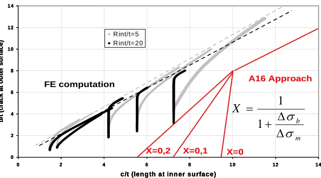
- the current procedure has been extended to pure bending stress loading conditions (See Figure 5). In fact, the A16 procedure [1], as well as the JAPC procedure, uses a master curve for post-penetrated crack length but for limited loading types (X>0.2) [18].
X=1 – Ri/t=5 X=0.25 – Ri/t=5
Figure 4: Master curve extension for piping
0 2 4 6 8 10 12 14
0 2 4 6 8 10 12
c/t (leng th at inn er su rface)
b
/t (crack at o
u
ter su
rface)
R int/t=5 R int/t=20
A16 Approach
FE computation
m b
X
σ
σ
∆
∆
+
=
1
1
Figure 5:Crack shape evolution after wall penetration
5.5.4 Summing up
Recent and ongoing work mainly shows that the present RCC-MR A16 appendix LBB procedure leads to significant overestimations of the size of the expected detectable defects when applied to HTR components. Further experimental and theoretical works are needed to answer the pending questions, as a possible reduction of the margins.
Validation extensions of the procedure (cf. § 5.5.3) have been conducted. Evaluation of leak area with complex crack shape is in progress [3].
6 EXPERIMENTAL WORKS
6.1 Description of Main Features
Previous experimental work was done for the Superphénix plant on piping systems (c.f. § 6.4) and on large plates for the former EFR program (c.f. §6.5). Specimens were made of austenitic stainless steel.
Experimental work was carried out by the CEA in order to check some points of the A16 procedure [11]:
- main results related to the crack shape evolution were provided by the CHARLIE tests (piping) under high temperature conditions.
14
X=0 X=0,1
X=0,2
0 2 4 6 8 10 12 14
0 2 4 6 8 10 12 14
c/t (leng th at inn er su rface)
b
/t (crack at o
u
ter su
rface)
R int/t=5 R int/t=20
0 2 4 6 8 10 12 14
0 2 4 6 8 10 12 14
c/t (leng th at inn er su rface)
b
/t (crack at o
u
ter su
rface)
R int/t=5 R int/t=20
A16 Approach
FE computation
m b
X
σ
σ
∆
∆
+
=
1
1
X=0 X=0,1
X=0,2
- leak rate and COA were investigated under different conditions through CHARLIE and PLAFAR (plate) tests. - CHARLIE - FAR 3 is in connection with the instability of cracked piping under high cyclic loading (cf.§ 6.6). Specific tests are required for HTR applications (see § 6.2).
6.2 Helium Leak Tests DEDIFAR
The test program requires the definition of similar conditions to conduct tests at room temperature instead of high temperature. The ongoing test program is mainly composed of:
- the validation of the pressure drop under laminar leak with small values of the CMOD (δ), 25 and 200 µm. - the investigation on the effect of diverging Crack Opening Profile (COP), and that of the converging COP, - a ”global” test with real crack shape or, if required, a specific test to account for complex COP.
6.3 CHARLIE – FAR 1 test
The actual through-wall-crack obtained after 499 cycles under creep-fatigue crack growth was characterised by two lengths, L1 = 47,5 mm and L2 = 7 mm (See Figure 6), which are the dimensions of the crack on the skins of the tube. After that, water leak tests were performed.
The calculation of the crack-opening-displacement considers the minimal size of the crack, and this assumption leads to underestimate the crack-opening area and, consequently, the leak rate. An equivalent crack length, based on an average crack length is proposed by [19]. Better results are obtained using a more realistic assumption for the crack length, as shown in Figure 6. As mentioned in section §5.5.2, on going work [3] is looking at this issue.
L1 = 7 mm (rear surface)
δ
L2= 47.5 mm (front surface)
L1 = 7 mm (rear surface)
δ
L2= 47.5 mm (front surface)
L1 = 7 mm (rear surface)
δ
L2= 47.5 mm (front surface)
L1 = 7 mm (rear surface)
δ
L2= 47.5 mm (front surface)
Figure 6:CHARLIE - FAR 1 Test: Calculated/experimental crack opening δ (L_eq: Equivalent crack length)
6.4 SPX1 Elbow Test
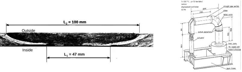
A large scale elbow is submitted to a cyclic bending load [20], Figure 7 shows experimental device. A longitudinal initial notch is located at the crown (outer skin), which is well known to be the worst location for LBB demonstration. The master curve is found to be quite pessimistic, leading to about two times the crack length at wall breakthrough. In addition, the back face crack length is significant (47 mm). The ratio (L2-L1)/L2 is then about 0.53 (see figure 7). The A16 procedure is found to be pessimistic with large margins.
L2= 100 mm
L1= 47 mm
Outside
Inside
L2= 100 mm
L1= 47 mm
L2= 100 mm
L1= 47 mm
Outside
Inside
Figure 7:SPX1 Elbow Test - Just Through Wall Crack at Wall Breakthrough
6.5 Large PLATE Test
A through wall crack in large plate was obtained under pure bending load [21]. Low cycle range was applied which leads to long crack length at wall breakthrough (pessimistic) and one and a half million cycles was needed. The wall thickness of the 2 m x 2 m test plate is 35 mm and the initial crack (3 mm deep x 170 mm long), is the maximal realistic
technological defect relevant for a SFR main vessel. The exponent of the Paris law is quite high at about 4,3 (pessimistic). Up to a depth of about 70% the wall thickness, the crack length does not change significantly (cf. figure 8) despite the large number of cycles (3 105 cycles). The master curve is found to be pessimistic and the “back face” crack length is significant (230 mm) at wall breakthrough. The ratio (L2-L1)/L2 is then 0.63, which is favourable to LBB.
0 5 10 15 20 25 30 35
0 100 200 300 400
Crack semi-length [mm]
C rack d e p th [m m ] experimental results w all breakthrough
negligible crack length changes
rear surface
front surface 0
100 200 300 400 500 600 700 800 900
0 1 2 3 4 5
Million of cycles
S e mi -c ra c k l e ngt h [ m m] Top surface bottom surface
L1= 230 m m
L2= 620 m m
t At wall breakthrough
0 100 200 300 400 500 600 700 800 900
0 1 2 3 4 5
Million of cycles
S e mi -c ra c k l e ngt h [ m m] Top surface bottom surface
L1= 230 m m
L2= 620 m m
t At wall breakthrough
L1= 230 m m
L2= 620 m m
t At wall breakthrough
Figure 8:Large plate through wall crack shape up to and after breakthrough
The calculated leak rates, using DCRC procedure [8], were found smaller than the experimental results. A residual crack opening area was observed due to plastic effects, which is also favourable to LBB.
6.6 CHARLIE - FAR 3 test
The validation of the computation of the limiting crack length (2CG) has to address a large number of issues, such as:
- large crack extension prediction and aging effects,
- applicability of J under non proportional loadings,
- crack growth under combined fatigue and tearing.
The test specimen is an aged butt joint piping containing through-wall-crack submitted to fully reverse cyclic tension/compression loading (global bending moment), at room temperature.
A thermal ageing treatment of 3000 hours at 650°C was conducted on a weld junction in order to take into account operating conditions on the tearing characteristics.
Crack growth calculations using A16 procedure were conducted. The number of cycles leading to the propagated crack length was found to be in quite good agreement with experimental results and slightly pessimistic.
Further works could deal with evaluation of the cyclic effect on the J-R curve on the basis of IPIRG results [22].
7 IMPROVEMENTS NEEDED FOR HTRs and SFRs
The main technical issues are pointed out here and are related to:
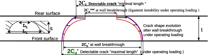
- The crack shape at wall breakthrough accounting for ligament instability (c.f. Figure 9).The aim is to define a realistic shape of the through wall crack which could be defined by the ratio L2/L1 or (L2-L1)/L2.
- The leak area with complex crack shape, i.e., different crack lengths, L1 and L2, on the opposite sides of the wall thickness. An on-going program is aimed at solving this issue for HTR conditions [3].
- The limiting crack length evaluation (2CG) under large crack extension and/or high cyclic loading conditions.
2Cp’at wall breakthrough
t
2C
LDetectable crack"minimal length "2Cprearat wall breakthrough (ligament instability under operating loading )
2C
d’
Detectable crack "maximal length" (under operating loading )L
1L
2t
Crack shape evolution after wall breakthrough under operating loading
Front surface Rear surface
2Cp’at wall breakthrough
t
2C
LDetectable crack"minimal length "2Cprearat wall breakthrough (ligament instability under operating loading )
2C
d’
Detectable crack "maximal length" (under operating loading )L
1L
2t
L
1L
2t
Crack shape evolution after wall breakthrough under operating loading
Front surface Rear surface
Figure 9:Realistic Crack Shape Through the Wall Thickness for relevant COP
8 CONCLUSIONS
Improvements on methodology have been conducted in order to extend and validate the LBB procedure and experimental work has been carried out.
For HTRs, pressurized helium is favourable to a reliable LBB demonstration. A detectable leak rate is expected even though the Crack Opening Area is low. Relevant helium leak models and the related experimental validations are under progress. Besides, Crack Opening Profiles of a TWC of complex shape under representative mechanical cyclic loads are studied and the first results tend to show that a reduction of the margins of the A16 LBB procedure for HTR applications might be proposed and justified.
For SFR conditions, the application of LBB procedure leads to conservative results, and good correlation with experimental results is generally observed. The crack shape after wall penetration has been found to be conservatively evaluated, either under fatigue or creep fatigue conditions.
In a nutshell, further theoretical and experimental work is necessary to adapt and consolidate the methodology for potential ANTARES applications (HTRs) and to limit overestimations of the size of the expected detectable cracks (HTRs and SFRs). This paper also discusses improvements that would be needed for potential applications in the near future.
REFERENCES
1. RCC-MR, "Design and construction rules for mechanical component of FBR nuclear island", Tome I – Volume Z - Appendix A16 "Guide for Leak Before Break and defect assessment ", Edition 2002 – AFCEN
2. Drubay B., Marie S., Chapuliot S., Lacire M.H., Michel B., Deschanels H. - A16 "Guide for defect assessment at elevated temperature", PVP 80 (2003) 499-516
3. Krakowiak C., Kayser Y. and Deschanels H. “Leak Before Break procedure for high temperature Reactors – Crack Opening Profile Studies for Complex-Shaped Defects in Thick Components
4. NUREG 1061 Vol.3 “Report of the US NRC Piping Review Committee. Evaluation of Potential for pipe Breaks” – Nov. 1994
5. "Leak before break assessment of pressurised components" EUR 17574 EN European Commission Nuclear Science and Technology
6. Milne I. et al., "Assessment of the Integrity of Structures Containing Defects", R/H/R6 – Revision 4, May 2006. 7. BS7910 Annex F “Guide on methods for assessing the acceptability of flaws in metallic structures”, 1999
8. EFR B40151465/B DCRC Committee Report 13 "Leak before break procedures for sodium boundary components". December 1992
9. Shimakawa T., Miura N., Fujioka T, Kashima K., Nitta A. “Flaw assessment methodology for FBR components 13rd SMIRT conference, Porto Alegre, Brasil – August 1995
10. Miura N., Nakayama Y. and Tkahashi Y. “Development of Flaw Evaluation Guideline for FBR Components 15th SMIRT, Seoul, Korea, 1995, pp. V-137-144
11. Deschanels H., Drubay B., Michel B., Cambefort P., Marie S. “Leak Before Break procedure for high temperature applications – Improvements and Validation” ICAPP ’03 Córdoba, Spain, May 4-7, 2003
12. Turbat A., Deschanels H., Spérandio M., Faidy C. ”The use of LBB concept in French fast reactors : Application to SPX plant” LBB 95 LYON
13. Deschanels H., Spérandio M., Turbat A. ”Numerical simulations of crack opening areas for LBB applications SMIRT 13 Conference, paper E01/3 – Porto Alegre, Brasil – August 1995
14. Bhandari S., Deschanels H., Spérandio M., Faidy C., Setz A.W. Tests on large scale LMFBR piping, Part II: Analysis of through-cracked straight pipes DN700 tested under bending at RT and 550°C, SMIRT 12 Conference, Stuttgart (15-20. Aug. 1993) paper GF10/2
15. R Comolet Mécanique expérimentale des fluides Tome II “Dynamique des fluides réels” 4ème édition Masson 1994. 16. Lejeail Y. Cabrillat M.T., Krakowiak C., "Application of a Leak Before Break Procedure to a HTGR Cross-Duct"
HTR 2004 Conferences
17. Kayser, Y., Marie, S., Poussard, Ch. And Delaval, Ch., "Leak before Break procedure – Recent Modifications of RCC-MR A16 Appendix and Proposed Improvements", Proposed at International Journal of Pressure Vessels and Piping, IPVP-D-07-00003, Under Review.
18. Nam K.W, Ando K., Ogura N. and Matui K., "Fatigue life and penetration behaviour of a surface-cracked plate under combined tension and bending", Fatigue Fract. Engng. Mater. Struct. Vol. 17, No. 8, pp. 873-882, 1994 19. AHN S.H. and al, Fatigue crack growth and penetration behaviour in pipe subjected to bending load", SMIRT 14,
Lyon 1997.
20. Large scale elbow test "Fracture mechanics considerations in breeder reactor design" Final report 1984, Novatome-Ident No.AFAL.MAT.850.GEN.SN.001
21. Sharples JK, Melvin G, O’Donnell IJ and Bate SK. Report Of Wide Plate Test SSTP13 to investigate Leak-Before-Break of EFR Primary Vessel. AEA/RS/4315, FR/SIWG/FESG/P(93)63
22. Wilkowski G., Olson R., Scott P., Hopper A., Mayfield M., "The IPIRG Programs – Advances in Pipe Fracture Technology", LBB95 specialist meeting on Leak Before Break, Lyon, France 1995, Oct 9 - 11, Proceedings of the U.S. Nuclear Regulatory Commission, NUREG CP-0155, 1997.