Design and Fabrication of Regenerative
Braking System and Modifying Vehicle
Dynamics
D.Kesavaram 1, K.Arunkumar 2, M.Balasubramanian 3, J.Jayaprakash 4, K.Kalaiselvan 5
Assistant Professor, Department of Mechanical Engineering, TRP Engineering College, Tiruchirapalli, India1
UG Scholars, Department of Mechanical Engineering, TRP Engineering College, Tiruchirapalli, India 2,3,4,5
ABSTRACT: A regenerative brake is an energy recovery mechanism which slows a vehicle or object by converting
its kinetic energy into a form which can be either used immediately or stored until needed. The conventional brake setup involves many energy loses and hence in our work, the conventional brake setup is replaced by mounting an alternator assembly in the wheel hub. During the forward motion of the vehicle, the alternator’s rotor rotates freely. During the application of brakes, the input supply is given to the alternator and as a result the rotor coils provide a rotational magnetic flux which cuts the stator conductor which is rotating along with the flywheel and hence an induced voltage is obtained from the alternator output which is stored in a battery. By increasing the alternator load the conductor gradually slows down and hence acts as a brake. The time required to stop the vehicle is directly proportional to the load connected to the alternator. Then by increasing the diameter of the front wheel of the vehicle, the stability of the 2 wheeler can be improved as it modifies the rear suspension effect and provides more contact between the wheel and the ground during braking. The suspension action can also be utilized for any useful purpose by placing a piston and cylinder arrangement having one-way valve lead to compressed air tank.
1. INTRODUCTION
A brake is a mechanical device that inhibits motion by absorbing energy from a moving system. It is used for slowing or stopping a moving vehicle, wheel, axle, or to prevent its motion, most often accomplished by means of friction.Most brakes commonly use friction between two surfaces pressed together to convert the kinetic energy of the moving object into heat, though other methods of energy conversion may be employed. Still other braking methods even transform kinetic energy into different forms, for example by transferring the energy to a rotating flywheel. When the brake pedal of a modern vehicle with hydraulic brakes is pushed against the master cylinder, ultimately a piston pushes the brake pad against the brake disc which slows the wheel down. On the brake drum it is similar as the cylinder pushes the brake shoes against the drum which also slows the wheel down.
1.1 Brake components
Brake Pads: steel backing plates used in disk brakes; friction material is bound to the surface facing the rotor
and is usually made of ceramic, metal or other hard-wearing composite materials
Brake Shoes: 2 pieces of sheet steel welded together that carry the brake lining
Brake Drum: rotating drum-shaped component used in drum brakes
Brake Lining: heat-resistant, soft but tough material with a high friction characteristic housed inside a brake
shoe
Rotor: cast iron brake disc connected to wheel and/or axle; sometimes made of reinforced carbon-carbon,
ceramic matrix or other composite
Piston: a moving component contained by a cylinder
o Floating Calipers: moves relative to rotor; uses a piston on a single side of disc to push inner brake pad into braking surface before pulling caliper body in to apply pressure on opposite side of disc; also known as a sliding caliper
o Fixed Calipers: does not move relative to rotor and is sensitive to imperfections; uses one or more
single pairs of opposing pistons to clamp from each side of the rotor
Disc Brakes: A friction system using a wheel brake to slow the rotation of the automobiles wheels; brake pads
are pushed against the brakes rotor with a set of calipers
Drum Brakes: A friction system using a set of shoes or pads to press against a brake drum
Single-Circuit Hydraulic Brakes: A master cylinder fed by a reservoir of hydraulic brake fluid and
connected by a system of metal pipes and rubber fittings attached to wheel cylinders.
Antilock Braking System (ABS): an electrical control unit, hydraulic actuator and individual wheel speed
sensors that work together to prevent brakes from locking up when they are slammed on by rapidly pumping brakes when a potential lockup is detected; each wheel is controlled individually to maintain traction
Power Brake Booster: a system utilizing the vacuum power naturally produced in an engine to amplify a
drivers foot pressure to stop even very heavy vehicles
Air Brakes: a system using air instead of hydraulic fluid to activate a standard disc or drum brake, usually used in buses, trucks and trailers
Advanced Emergency Braking System (AEBS): an autonomous safety system that employs sensors to
monitor a vehicles proximity to others in the vicinity. Brake systems, whether powered by air, hydraulics or computer, are engineered for automotive safety. Service brakes allow drivers to stay safe while manoeuvring their vehicle in ordinary driving situations. Another form of brakes makes up the system in a passenger vehicle, in order to protect from a collision while stopped parking brakes.
II. PROBLEM IDENTIFICATION
2.1 Drum Brakes – Problems
Drum brakes, like most other brakes, convert kinetic energy into heat by friction This heat should dissipate into the surrounding air, but can just as easily transfer to other braking system components. Brake drums must be large to cope with the massive forces involved, and must be able to absorb and dissipate a lot of heat. Heat transfer to air can be aided by incorporating cooling fins onto the drum. However, excessive heating can occur due to heavy or repeated braking, which can cause the drum to distort, leading to vibration under braking.
The other consequence of overheating is brake fade.[4] This is due to one of several processes or more usually an accumulation of all of them.
1. When the drums are heated by hard braking, the diameter of the drum increases slightly due to thermal
expansion, so the shoes must move farther and the driver must press the brake pedal farther.
2. The properties of the friction material can change if heated, resulting in less friction. This can be a much larger
problem with drum brakes than disc brakes, since the shoes are inside the drum and not exposed to cooling ambient air. The loss of friction is usually only temporary and the material regains its efficiency when cooled, but if the surface overheats to the point where it becomes glazed the reduction in braking efficiency is more permanent. Surface glazing can be worn away with further use of the brakes, but that takes time.
2.2 Energy loss through heat
due to adverse weather conditions. The water reduces the frictional properties of the brake system and must be removed to restore braking ability. This is a very dangerous situation and drastically reduces the stopping ability of the vehicle until the system is dry. The use of many clips and springs makes overhaul of the brake drum assembly very time-consuming. Because of the enclosed drum.asbestos dust is collected in the brake cavity and certain parts of the brake drum.
2.3 Disk brakes – Problems
1. It is expensive compare to drum brake.
2. More skills require to operate disk brake compare to drum brake that’s the reason why some people are not
comfortable with disk brake
3. If any air remains in disk brake system, it can cause accident as the brake will not work effectively.
4. Disk brake assembly has more moving parts and much complex than drum brake.
5. It requires lot of effort at maintenance front like brake fluid (bleeding), change of brake pads etc compare to
drum brake.
6. Brake squeal occurs due to vibrations between the brake disk/rotor and brake pads or brake pads and caliper.
Brake noise occurs due to reason other than mentioned in brake squeal.
7. Apart from above mentioned maintenance tips brake squeal can be reduced by installing insulator shims on the
back of brake pads. It provides cushion to brake pads and reduce vibrations. You can also apply moly-based dry lubricant on the back of pads or apply a noise suppressing compound on the back of pads to reduce vibrations. If the manufacturer has provided semi-metallic pads then it can also be reason of brake noise. You can use non-metallic ceramic pads or Non-asbestos organic pads to reduce noise. Sometimes the design of pads is also a reason for brake squeal.
2.4 Anti lock Brakes – Problems
Despite the fact that anti-lock brakes are proven to be a safety feature in most situations, and insurers consider them to significantly lower risk for a vehicle, not all drivers are sold on this option for a car or truck. Here are some of the down sides that drivers find in this kind of brake system.
Inconsistent stop times. However, some drivers report that they find stopping distances for regular conditions
are lengthened by their ABS, either because there may be errors in the system, or because the clunking or noise of the ABS may contribute to the driver not braking at the same rate.
Expense. An ABS can be expensive to maintain. Expensive sensors on each wheel can cost hundreds of
dollars to fix if they get out of calibration or develop other problems. For some, this is a big reason to decline an ABS in a vehicle.
Delicate systems. It's easy to cause a problem in an ABS by messing around with the brakes. Problems include
disorientation of the ABS, where a compensating brake sensor causes the vehicle to shudder, make loud noise or generally brake worse.
2.5 Braking torque
Torque is a force exerted on an object; this force tends to cause the object to change its speed of rotation. A car relies on torque to come to a stop. The brake pads exert a frictional force on the wheels, which creates a torque on the main axle. This force impedes the axle's current direction of rotation, thus stopping the car's forward movement.
2.5.1 Determination of hydraulic braking torque
Assumptions
No. of piston, n = 2
Diameter of piston, D = 40 mm
Coefficient of friction, µ= 0.9
Piston area, A = (πd2 /4)*2
= 2512 X10-6 m2
Pressure of Fluid, P = 30 psi
= 3.44 x 10⁵ N/m2
Braking torque, T = µ*n*P*A*R
Where
R= Distance at which pressure is applied from the Centre
T = 0.9*2*3.44 x 105*2512 X10-6*75x10-3
T = 62.21 Nm
Braking Torque, T = 62.21 Nm
2.5.2 Damping energy loss
Assumptions:
Mass of the vehicle, m =150 Kg
Stiffness, k = 75 N/mm = 75*103 N/m
Damping ratio, E = 0.8
W = 22.36 rad/sec
Wd = Wn2– a2
Wd =22.362-1.792
Wd =22.28 rad/sec
Time period, tp =2 /wd
tp =0.282 secs
Potential Energy Loss
U =(K*u2)/2 U= 6.619 KJ Kinetic Energy Loss
T = (m*v2)/2
T=5.671 KJ
Total energy loss, E = K + T E = 6.619 + 5.671 E = 12.362 KJ
III. PROCESS METHODOLOGY
3.1 Regenerative braking
A regenerative brake is an energy recovery mechanism which slows a vehicle or object by converting its kinetic energy into a form which can be either used immediately or stored until needed. This contrasts with conventional braking systems, where the excess kinetic energy is converted to unwanted and wasted heat by friction in the brakes. In addition to improving the overall efficiency of the vehicle, regeneration can greatly extend the life of the braking system as its parts do not wear as quickly.
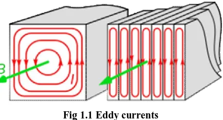
3.2 Eddy currents
Fig 1.1 Eddy currents
(left) Eddy currents (I, red) within a solid iron transformer core. (right) Making the core out of thinlaminations parallel to the field (B, green) with insulation between them reduces the eddy currents. Although the field and currents are shown in one direction, they actually reverse direction with the alternating current in the transformer winding.
Eddy currents generate resistive losses that transform some forms of energy, such as kinetic energy, into heat. This Joule heating reduces efficiency of iron-core transformers and electric motors and other devices that use changing magnetic fields. Eddy currents are minimized in these devices by selecting magnetic core materials that have low electrical conductivity (e.g., ferrites) or by using thin sheets of magnetic material, known as laminations.
Induction heating makes use of eddy currents to provide heating of metal objects.
3.3 Steps involved
Step 1 : Part identification & selection
Step 2: Calculating the braking torque
Step 3: Design of the setup
Selecting the components Arranging the components
Fixing the components using fasteners
Step 4: Provide supply to Alternator input
Step 5: Calculating the electrical energy obtained
IV. ENERGY RECOVERY MECHANISM
4.1 Energy Stored In A Vehicle
Flywheel energy storage works by accelerating a rotor (flywheel) to a very high speed and maintaining the energy in the system as rotational energy. When energy is extracted from the system, the flywheel's rotational speed is reduced as a consequence of the principle of conservation of energy.
4.2 Determination Of energy Stored In A Vehicle
Assumptions
Weight of the vehicle, Wv= 150 Kg
Weight of the rider, Wr= 50 Kg
Total Weight, Wt = Wv+ Wr
= 150+50
Wt =200 Kg
Speed of the vehicle, V = 60 km/hr
=60*5/18 m/sec
Kinetic Energy, E = mv2/2
= 200*16.672/2 = 27788.89 kgm2/sec2
4.3 Experimental Components 4.3.1 Brake disc
A disc brake is a type of brake that uses calipers to squeeze pairs of pads against a disc in order to create friction that retards the rotation of a shaft, such as a vehicle axle, either to reduce its rotational speed or to hold it stationary
Fig 1.2 Metallic Brake disc 4.3.2 Alternator
An alternator is an electrical generator that converts mechanical energy to electrical energy in the form of alternating current. A conductor moving relative to a magnetic field develops an electromotive force (EMF) in it.
Fig 1.3 14.2V Lucas TVS Alternator
4.3.3 Flywheel
We found difficulty in testing this setup in an automobile, So that we made a separate setup consists of flywheel and an alternator coupled to it.
The flywheel is designed to store certain energy and the experiment is done based on how much input current should be given to nullify the energy to stop the flywheel. The results were theoretically compared with other application of automobile
Energy stored in a flywheel
Weight of the flywheel = 10kg
Velocity of rotation = ΠDN/60
Speed of rotation =1100 RPM
Diameter of flywheel =20cm =0.2m
Energy stored = mv2 /2
Fig 1.4 Assembled view
V. RESULTS AND DISCUSSION
Table 1.1 Braking time
S.No SPEED
(RPM)
LOAD VOLTAGE
(Volt)
CURRENT (Amps)
TIME (Secs)
1 1100 0 14.5 - 5.15
2 1100 1 12.5 0.9 4.74
3 1100 2 12 1.6 4.53
4 1100 3 11.8 2.5 3.91
5 1100 4 11.5 2.9 3.59
6 1100 5 11.2 3.8 2.80
Table 1.2 Energy recovered
S.No LOAD POWER
(Watts)
ENERGY
(Joules) %ENERGY RECOVERED
1 0 - - -
2 1 11.25 53.325 8.055
3 2 19.2 54.36 8.211
4 3 29.5 44.84 6.77
5 4 33.35 41.285 6.236
6 5 42.56 42.56 6.429
Mean energy recovered = 7.141% of energy
From the above table 1.2, we found that with increase in load the alternator tends to slow down as the amount of current required is high. Hence the flywheel connected to the alternator also tends to slow down which results in braking effect.The load to alternator can be increased either by using an external load or by increasing the number of batteries connected to the alternator. The time required to bring the flywheel to rest is directly proportional to the load connected.
5.1 Energy Recovered From Various Automobiles (Theoretical Values)
Assume all the vehicles are travelling at 60Km/Hr and the passengers travelling in it are travelling with a mass of 50Kg each.
Table 1.3 Theoretical values
VEHICLE WEIGHT (TONNES)
NET WEIGHT (TONNES)
ENERGY STORED
(KILOJOULES) ENERGY RECOVERED (KJ)
Bike 0.15 0.2 27.78 1.98
Car 1.5 1.8 250.1 17.86
Bus 16.2 19.2 2667.733 190.5
Truck 16.2 25.2 3501.4 250.03
Train 112.8 1080 15006 1071.578
5.2 Vehicle Stability 5.2.1 Centre of Gravity
Centre of gravity of a body is that point, through which the resultant of the system of parallel forces formed by weights of all the particles constituting the body passes for all positions of the body. In a uniform gravitational field, it is also known as the "Centre". It is denoted as "C.G" or "G"
5.2.2 Determination Of Centre Of Gravity
Height of Centre of Gravity = H1+[ ]
Where
Ln = New wheelbase =
Data’s from splendor plus bike
L1 =127 cm
H1 =30 cm
H2 =35 cm
W1 =70 Kg
W2 =80 Kg
W3 =75 Kg
Total weight WT = 150 Kg
Wf =75-70 = 5 Kg
Ln =
= 122.08 cm
H = 30+ [ ]
Height of CG = 44.765 cm from the ground
Wheelbase
Weight acting Weight acting
On front wheel on rear wheel
Front wheel weight percentage = = 0.4667
Rear wheel weight percentage = = 0.5333
CG from front wheel = 0.4667 * wheel base
= 0.4667*127 = 59.27 cm
CG from rear wheel = 0.5333* wheelbase
5.2.3 Inference
During the application of sudden brakes, the back wheel of a vehicle tends to create a moment with respect to the back
axle, hence it decreases the point of contact between the wheel and the road and so skidding occurs. To
overcome this, if we increase the diameter of the front wheel, the back wheel tends to create moment in the counter
direction which helps to provide more stability to the vehicle while braking. By placing a piston and cylinder
arrangement connecting to a tank using a one way valve, the suspension action can be obtained as a compressed air output.
VI. CONCLUSION
Thus the energy wasted due to damping effect and the inertia of the vehicle is recovered as Equivalent electrical energy and it has no moving parts, hence no wear and tear. The load to alternator can be increased either by using an external load or by increasing the number of batteries connected to the alternator. The time required to bring the flywheel to rest is directly proportional to the load connected. The friction brake is a necessary back-up in the event of failure of the regenerative brake as the regenerative braking effect drops off at lower speeds, and cannot bring a vehicle to a complete halt reasonably quickly. Regenerative and friction braking must both be used, creating the need to control them to produce the required total braking. The mean energy required from this braking system is about 7.141 % of total energy required to provide the braking in conventional methods.
By modifying the vehicle dynamics, the suspension effect can be altered which will give more stability to the vehicle, because it provides more contact between rear wheel and the ground .The suspension action can also be utilized for any useful purpose by placing a piston and cylinder arrangement having one-way valve lead to compressed air tank.
REFERENCES
1. Engine braking system using alternator stator windings -Michael J. Dins, Michael R. Kleczewski,Robert K. Lindorfer, Jr., Hal R. Johnson
2. Electric vehicle having dynamic braking and regeneration-Marvin D. Jennings
3. Method for eliminating fuel use during dynamic braking -AjithKuttannair Kumar, Peter Loring Valentine
4. Apparatus for providing controlled mechanical braking torque -Rodney E. Schwartz, Steven T. Clauter, Gary M. Orman
5. Enginebraking system usingalternator stator windings -Robert K LindorferJr, Hal R Johnson, Michael R Kleczewski, Michael J Dins
6.