Fast Fourier Transform Using Advanced
Processor
K.Vijayalakshmi, K.Jyostsna Vanaja, R.Sruthi,
Asst. Professor, Dept. of ECE, CIET, India
Dept. of ECE, CIET, India
Dept. of ECE, CIET, India
ABSTRACT: OFDM systems are widely used in both wired and wireless communication systems. FFT/IFFT is one of
the key processing in the implementation of OFDM systems such as WiBro, DAB and UWB systems. Most of the researches on the implementation of FFT processors have focused on reducing the complexities of multipliers, memory and control circuits involved in the IFFT/FFT process. Modification in the architecture for pipelined FFT processor is proposed, to reduce the register size required for FFT processor. In OFDM, the FFT processors are used at the receiver side of the system. The single-path delay-feedback architecture is used to exploit the spatial regularity in signal flow graph of the algorithm.
KEYWORDS: FFT- Fast Fourier Transform, IFFT – Inverse Fast Fourier Transform, OFDM – Orthogonal Frequency
Division Multiplexing, WiBro – Wireless Broadband, DAB – Distributed Audio Band.
I. INTRODUCTION
IEEE 802.11a , HIPERLAN standard uses Orthogonal frequency division multiplexing as Modulation and Multiplexing technique for many communication systems such as WiBro, DMB, DVB-T, and DSL [1] [2].OFDM is commonly implemented in many emerging communications protocols because it provides several advantages over the traditional FDM approach in the dispersive environment. More specifically, OFDM systems provides greater spectral
efficiency, reduced inter symbol interference (ISI), and it is resilience to multi-path distortion. FFT/IFFT processor is one of the key components in the implementation of OFDM systems. Various researches have
been carried out to design efficient FFT processors in terms of area and power. In general, it is known that pipeline FFT architectures have suitable properties for VLSI implementation of real-time applications [3] ~ [7]. It is known that R2iSDF (Radix-2i Single-Path Delay Feedback) FFT architecture is one of the most efficient FFT structures in terms of memory and control circuit. Radix-22 FFT algorithms have the same multiplicative complexity as radix-4 algorithms, but still retains the simple radix-2 butterfly structures [7- 8]. The need for large point-size FFT processors has been increased due to the increasing demand for broadband and mobility in communication systems. While the number of FFT stages increases logarithmically as the FFT point-size increases, the number of required registers increases linearly. In large point-size FFT designs, the registers occupy more than 70% of the chip area, which causes severe restrictions to the chip design. In most OFDM systems, the number of different input signals to FFT in the receiver is limited. As an example, in 16-QAM systems, the FFT receives only 16 different input signals. In this paper, we propose a register size reduction method based on the observation that the number of different FFT input signals is limited in most OFDM systems. In addition, we focus on reducing the registers in the first two stages in FFT architecture since the two stages require 75% of the total registers.
FFT & IFFT IN OFDM: The Fast Fourier Transform (FFT) and its inverse (IFFT) is one of the fundamental
converted into frequency domain signal. (Complex form) IFFT operation converts the frequency domain signal into the time domain signal. This time domain signal is same as that of the OFDM signal. In OFDM systems, subcarriers are generated by IFFT process, on which the information is mapped and is transmitted through the dispersive channel after up-conversion. At the receiver side and the FFT process is used. The Cooley–Tukey algorithm, named after J.W. Cooley and John Tukey, is the most common fast Fourier transform (FFT) algorithm. It re-expresses the discrete Fourier transform (DFT) of an arbitrary composite size N = N1N2 in terms of smaller DFTs of sizes N1 and N2, recursively, in order to reduce the computation time to O(N log N) for highly-composite N (smooth numbers). In FFT the input signals are in the normal order and the output signals are in the reverse order. In IFFT the input signals are in the reverse order and the output signals are in the normal order.The DFT of the first N/2 points and combine them in a special way with the DFT of the second N/2 points to produce a single N-point DFT. Each of these N/2-point DFTs can be calculated using smaller DFTs in the same way. One (radix-2) FFT begins, therefore, by calculating N/2 2-point DFTs. These are combined to form N/4 4-point DFTs. The next stage produces N/8 8-point DFTs, and so on, until a single N-point DFT is produced [3].
Processor & Butterfly Operation: The principle of FFT algorithm is based upon decomposing the computation of
DFT of a sequence of length ‘n’ into successive smaller DFT. Parallel data streams are used as inputs to an IFFT. The input is in the normal order and the output is in the bit-reversed order. The algorithm has an in-place calculation, which leads to reuse of available memory. The basic computational element of the Fast Fourier Transform is the butterfly. Each butterfly requires one complex multiplication and two complex additions.
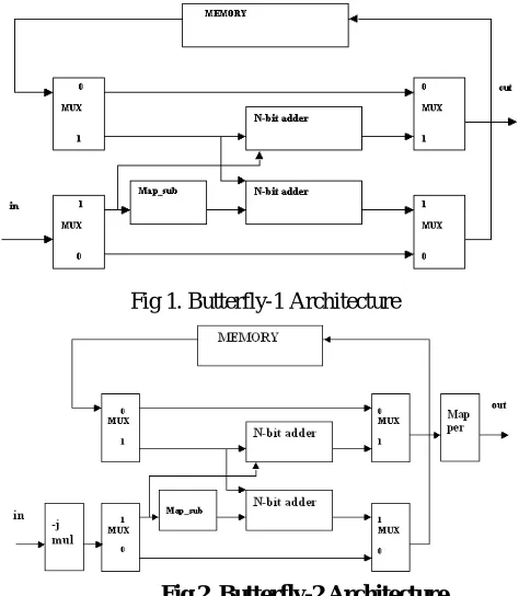
In the butterfly - 1 architecture, if the mux select value is zero then no operation is performed. If the mux select value is one then the two inputs are added in the N-bit adder unit. At the Map_sub block the negative conversion of the input value is takes place and then is added with another input value in the N- bit adder unit. These output values are stored in the memory for the next operation. The same operation is performed in the butterfly-2 structure, but at the input side –j multiplier operation is performed. The pipeline FFT processor can be divided into three main building blocks. i.e. memory, simplified butterfly elements and complex multipliers. Each stage in FFT is computed with a set of processing elements and the result is fed back to the same processing elements for the computation of next stage.
Fig 1. Butterfly-1 Architecture
The orthogonality allows for efficient modulator and demodulator implementation using the FFT algorithm on the receiver side, and inverse FFT on the sender side. Although the principles and some of the benefits have been known since the 1960s, OFDM is popular for wideband communications today by way of low-cost digital signal processing components that can efficiently calculate the FFT. In OFDM serial input data is converted into parallel input data. After conversion, base band modulation technique is applied such as PSK, QPSK, and QAM etc... After this operation, data converted into frequency domain signal (complex form) IFFT operation converts the frequency domain signal into the time domain signal. This time domain signal is same as that of the OFDM signal.At the receiver side, the original information is added with noise signal. That noise signals removed by simple equalization technique with one tab or two-tab equalizer. Then the FFT operation coverts the time domain signal into the frequency domain signal. After performing these operations, the parallel data is converted into the serial data.
II. PIPELINE SYSTEMS
Pipeline FFT processor is a specified class of processors for DFT computation utilizing fast algorithms. It is characterized with real-time, non-stopping processing as the data sequence passing the processor. It is an AT2 non-optimal approach with AT2 = O(N3),since the area lower bound is O(N). However, as it has been speculated [l] that for real-time processing whether a new metric should be introduced since it is necessarily nonoptimal given the time complexity of O(N). Although asymptotically almost all the feasible architectures have reached the area lower bound [2], the class of pipeline FFT processors has probably the smallest “constant factor” among the approaches that meet the time requirement, due to its least number, O(logN), of Arithmetic Elements (AE).The difference comes from the fact that an AE, especially the multiplier, takes much larger area than a register in digital VLSI implementation. It is also interesting to note the at least R (1ogN) AEs are necessary to meet the real-time processing requirement due to the computational complexity of R (N1ogN) for FFT algorithm.
III. PIPELINE OPERATION
Another major area/energy consumption of the FFT processor comes from the memory requirement to buffer the input data and the intermediate result for the computation. For large size transform, this turns out to be dominating [3, 4]. Although there is no formal proof, the area lower bound indicates that the “lower bound” for the number of registers is likely to be Q(N).This is obviously true for any architecture implementing FFT based algorithm, since the butterfly at first stage has to take data elements separated N/r distance away from the input sequence, where ris a small constant integer, or the “radix”. Putting above arguments together, a pipeline FFT processor has necessarily R (log, N) AEs and R (N) complex word registers. The optimal architecture has to be the one that reduces the “constant factor”, or the absolute number of AEs (multipliers and adders) and memory size, to the minimum.
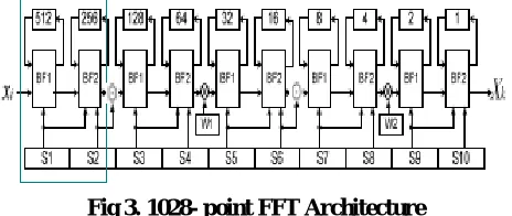
Fig 3. 1028- point FFT Architecture
IV. RESULTS
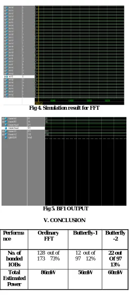
Fig 4. Simulation result for FFT
Fig 5. BF1 OUTPUT
V. CONCLUSION
Performa nce
Ordinary FFT
Butterfly-1 Butterfly
-2
No. of bonded
IOBs
128 out of 173 73%
12 out of 97 12%
22 out Of 97
13% Total
Estimated Power
Thus from the simulation, the above observation is made. It compares the conventional FFT process and the pipelined process as given by the proposed architecture. Simulation result clearly indicates that pipelined architecture uses less IOBs(Input and Output Bonds)The reduction is around 1/6th of that required for the conventional method. Similiarly the power dissipation by piplined architecture in average is around 37% less than the conventional one.Thus this paper tried to achieve a reduction in area required for FFT process. Also it gives reduction in power dissipated.
REFERENCES
[1] TTAS.KO-06.0064R1, Specifications for 2.3GHz band Portable Internet Service - Physical Layer, Telecommunications Technology Association, Dec. 2004.
[2] ETSI, “Digital Video Broadcasting (DVB): Framing Structure, Channel Coding and Modulation for Digital Terrestrial Television,” ETSI EN 300 744 v1.4.1, 2001.
[3] E. H. Wold and A. M. Despain, "Pipeline and parallel pipeline FFT processors for VLSI implementation," IEEE Trans. Comput., C-33(5), pp.414-426, May 1984.
[4] S. -S. He and M. Torkelson, “A new approach to pipeline FFT processor,” Proc. 10th Int’l Parallel Processing Symp. (IPPS ’96), pp. 766-770, 1996.
[5] Y. Chang and K. K. Parhi, "An efficient pipelined FFT architecture," IEEE Transactions on Circuits and Systems II, vol. 50, no. 6, pp. 322- 325, Jun. 2003.
[6] El-Khashab, A. M., Swartzlander, E. E., Jr. "A modular pipelined implementation of large fast Fourier transforms," IEEE Transactions on Signals, Systems and Computers, vol. 2, pp. 995-999, 2002.