PacketCable™ Applications
DECT SIP Specification
PKT-SP-DECT-SIP-I02-090917
ISSUED
Notice
This PacketCable specification is the result of a cooperative effort undertaken at the direction of Cable Television Laboratories, Inc. for the benefit of the cable industry and its customers. This document may contain references to other documents not owned or controlled by CableLabs. Use and understanding of this document may require access to such other documents. Designing, manufacturing, distributing, using, selling, or servicing products, or providing services, based on this document may require intellectual property licenses from third parties for technology referenced in this document.
Neither CableLabs nor any member company is responsible to any party for any liability of any nature whatsoever resulting from or arising out of use or reliance upon this document, or any document referenced herein. This document is furnished on an "AS IS" basis and neither CableLabs nor its members provides any representation or warranty, express or implied, regarding the accuracy, completeness, noninfringement, or fitness for a particular purpose of this document, or any document referenced herein.
© Copyright 2009 Cable Television Laboratories, Inc. All rights reserved.
Document Status Sheet
Document Control Number: PKT-SP-DECT-SIP-I02-090917 Document Title: DECT SIP Specification
Revision History: I01 – 02/26/09 I02 - 09/17/09
Date: September 17, 2009 Status: Work in
Progress
Draft Issued Closed
Distribution Restrictions: Author Only CL/Member CL/ Member/ Vendor
Public
Key to Document Status Codes
Work in Progress An incomplete document, designed to guide discussion and generate feedback that may include several alternative requirements for consideration.
Draft A document in specification format considered largely complete, but lacking review by Members and vendors. Drafts are susceptible to substantial change during the review process.
Issued A stable document, which has undergone rigorous member and vendor review and is suitable for product design and development, cross-vendor interoperability, and for certification testing.
Closed A static document, reviewed, tested, validated, and closed to further engineering change requests to the specification through CableLabs.
Trademarks
CableLabs®, DOCSIS®, EuroDOCSIS™, eDOCSIS™, M-CMTS™, PacketCable™, EuroPacketCable™,
PCMM™, CableHome®, CableOffice™, OpenCable™, OCAP™, CableCARD™, M-Card™, DCAS™, tru2way™, and CablePC™ are trademarks of Cable Television Laboratories, Inc.
Contents
1 SCOPE...1
1.1 Introduction and Purpose ...1
1.2 Requirements ...2
2 REFERENCES ...3
2.1 Normative References ...3
2.2 Informative References...3
2.3 Reference Acquisition ...3
3 TERMS AND DEFINITIONS ...4
4 ABBREVIATIONS AND ACRONYMS...5
5 OVERVIEW...6
5.1 DECT-SIP Reference Architecture...6
5.1.1 Functional Components...7
5.1.2 Protocol Interfaces ...8
5.2 Relationship to other specifications ...8
6 DECT-SIP REQUIREMENTS...10
6.1 Basic Calls ...10
6.1.1 Inbound Call ...10
6.1.2 Outbound Call ...11
6.1.3 PP initiated Call Release...12
6.1.4 Remote endpoint initiated Call Release ...13
6.1.5 Barge into Existing External Call...13
6.2 Common Feature Functions...14
6.2.1 Digit Maps ...14
6.2.2 Vertical Service Codes...15
6.2.3 Held Media ...15
6.2.4 Announcements ...15
6.2.5 In-Service and Out-of-Service States ...15
6.2.6 Early Media ...16
6.2.7 No Answer Timeout...17
6.3 Residential SIP Telephony Features ...18
6.3.1 Features with no additional DECT-SIP mapping requirement ...18
6.3.2 Caller ID...18
6.3.3 Call Forwarding Variable ...19
6.3.4 Selective Call Forwarding ...21
6.3.5 Hook-Flash Processing...21 6.3.6 Call Waiting...21 6.3.7 Call Hold ...22 6.3.8 Call Transfer...23 6.3.9 Three-Way Calling...27 6.3.10 Call History ...28 6.3.11 Emergency Services ...32 6.3.12 Do Not Disturb ...32 6.3.13 Distinctive Alerting ...32
6.3.14 Message Waiting Indicators ...32
6.3.15 Network-Based Call Screening ...33
A.1 Embedded Device (E-DVA) Requirements...35
A.2 Standalone Device (S-DVA) Requirements ...35
APPENDIX I ACKNOWLEDGEMENTS ...36
APPENDIX II REVISION HISTORY ...37
Figures
Figure 1 - E-DVA Reference Block Diagram...6Figure 2 - S-DVA Reference Block Diagram...7
Figure 3 - Inbound call ...11
Figure 4 - Outbound call with overlap sending ...12
Figure 5 - PP initiated call release ...13
Figure 6 - Remote endpoint initiated call release ...13
Figure 7 - Barge into existing external call...14
Figure 8 - Loss of Network Connectivity produces reorder tone...16
Figure 9 - Early Media...17
Figure 10 - Successful CFV Activation ...20
Figure 11 - CFV Status Change...21
Figure 12 - Call Waiting ...22
Figure 13 - PP initiated Call Transfer...24
Figure 14 - Remote endpoint initiated Call Transfer ...26
Figure 15 - Three Way Call ...28
Figure 16 - Auto Recall - Invocation ...30
Figure 17 - Auto Recall - Target becomes idle...31
Figure 18 - Message Waiting Indicator ...33
Tables
Table 1 - CFV Display Strings ...19Table 2 - SCF Display String...21
1 SCOPE
1.1
Introduction and Purpose
Note: All references to PacketCable in this document are PacketCable 2.0 unless specified otherwise.
This document specifies the requirements for implementing HD Voice services on the PacketCable infrastructure. It focuses on the functional specification of PacketCable client devices that extend the standard telephony functions to include:
a) DECT-based cordless telephony interface; b) Support for wideband voice; and
c) Interactions between the DECT cordless handsets and analog phones.
This specification introduces two types of the HD Voice client devices. One is an embedded device that integrates a DECT base station, a PacketCable client, and a DOCSIS cable modem; the other is a stand-alone device that integrates the first two elements but not a cable modem, and is connected to the PacketCable network via an external cable modem or router. The embedded device type is similar to an E-DVA, with the exception that it supports a DECT telephony interface in addition to analog telephony interfaces.
A substantial portion of the document is devoted to the requirements on the mapping between the signaling protocol on the DECT air interface and the PacketCable SIP signaling protocol on the network side. Special considerations are given to ensure that the user experience with the existing PacketCable feature set be preserved with the HD Voice client devices.
One general goal underpinning the development of this specification is to maximize the reuse of the existing PacketCable and DECT specifications and to minimize the changes to these specifications. In particular, no change is made to the PacketCable signaling protocol on the network side in order to support the HD Voice services, thus allowing the PacketCable infrastructure to be used as is. In addition, no major change is introduced to the DECT air interface signaling protocol. Rather, the document is mainly concerned with how to employ the existing DECT signaling scheme to realize the existing telephony features and how to bridge the signaling protocols on the air interface and the PacketCable network.
The scope of this specification is limited to the requirements that impact the device’s interoperability and the user’s basic feature interactions. No attempt is made to specify the device’s internal hardware and software architectures, the actual user interface, and supplementary functionality such as answer machine, phone book, etc. These areas, though important for a final product, are construed as either vendor-specific or operator-specific.
1.2
Requirements
Throughout this document, the words that are used to define the significance of particular requirements are capitalized. These words are:
"MUST" This word means that the item is an absolute requirement of this specification. "MUST NOT" This phrase means that the item is an absolute prohibition of this specification. "SHOULD" This word means that there may exist valid reasons in particular circumstances to
ignore this item, but the full implications should be understood and the case carefully weighed before choosing a different course.
"SHOULD NOT" This phrase means that there may exist valid reasons in particular circumstances when the listed behavior is acceptable or even useful, but the full implications should be understood and the case carefully weighed before implementing any behavior described with this label.
"MAY" This word means that this item is truly optional. One vendor may choose to include the item because a particular marketplace requires it or because it enhances the product, for example; another vendor may omit the same item.
2 REFERENCES
2.1
Normative References
In order to claim compliance with this specification, it is necessary to conform to the following standards and other works as indicated, in addition to the other requirements of this specification. Notwithstanding, intellectual property rights may be required to use or implement such normative references.
[CODEC MEDIA] PacketCable Codec and Media Specification, PKT-SP-CODEC-MEDIA-I07-090702, July 2, 2009, Cable Television Laboratories, Inc.
[DECT-HDV] PacketCable High Definition Voice with DECT Specification,
PKT-SP-DECT-HDV-I02-090917, September 17, 2009, Cable Television Laboratories, Inc. [DECT-PROV] PacketCable DECT Provisioning Specification, PKT-SP-DECT-PROV-I02-090917,
September 17, 2009, Cable Television Laboratories, Inc. [E-DVA] PacketCable Residential SIP Telephony E-DVA Specification,
PKT-SP-RST-E-DVA-I05-090528, May 28, 2009, Cable Television Laboratories, Inc. [EN 300 444] ETSI EN 300 444, Digital Enhanced Cordless Telecommunications (DECT); Generic Access
Profile (GAP), V2.1.1 (2008-10).
[PKT 24.229] PacketCable SIP and SDP Stage 3 Specification 3GPP TS 24.229,
PKT-SP-24.229-I05-090528, May 28, 2009, Cable Television Laboratories, Inc.
[RSTF] PacketCable Residential SIP Telephony Feature Specification, PKT-SP-RSTF-I05-090528, May 28, 2009, Cable Television Laboratories, Inc.
2.2
Informative References
This specification uses the following informative references.
[ARCH-FRM TR] PacketCable Architecture Framework Technical Report,
PKT-TR-ARCH-FRM-V06-090528, May 28, 2009, Cable Television Laboratories, Inc. [CMCI] DOCSIS Cable Modem to Custom Premise Equipment Interface,
CM-SP-CMCI-C01-081104, November 4, 2008, Cable Television Laboratories, Inc. [eDOCSIS] eDOCSIS Specification, CM-SP-eDOCSIS-I18-090529, May 29, 2009, Cable Television
Laboratories, Inc.
2.3
Reference Acquisition
• Cable Television Laboratories, Inc., 858 Coal Creek Circle, Louisville, CO 80027; Phone +1-303-661-9100; Fax +1-303-661-9199
• European Telecommunications Standards Institute (ETSI), 650, route des Lucioles, 06921 Sophia-Antipolis Cedex, France, Tel.: +33 (0) 4 92 94 42 00, Fax: +33 (0) 4 93 65 47 16,
3 TERMS AND DEFINITIONS
This specification uses the following terms:Digital Voice Adaptor Logical entity that is used to represent either E-DVA or S-DVA
Embedded Digital Voice Adaptor
The eDOCSIS device that integrates a DECT base station (FP) with a PacketCable E-DVA (embedded with cable modem)
Fixed Part The DECT base station
High Definition Voice The PacketCable service that offers wideband voice using DECT-based custom premise equipment
Information Element The constituent part of a DECT message
PacketCable Network The network that provides PacketCable services according to [ARCH-FRM TR]
Portable Part The DECT handset
Standalone Digital Voice Adaptor
The stand-alone device that integrates a DECT base station (FP) with a PacketCable client, separate from cable modem
4 ABBREVIATIONS AND ACRONYMS
This specification uses the following abbreviations:AS Application Server
DECT Digital Enhanced Cordless Telecommunications
DOCSIS Data-Over-Cable Service Interface Specification®
DVA Digital Voice Adaptor
E-DVA Embedded Digital Voice Adaptor
eDOCSIS Embedded DOCSIS
FP Fixed Part
HD High Definition
IE Information Element
NBCS Network-Based Call Screening
POTS Plain Old Telephone Service
PP Portable Part
RST Residential SIP Telephony
S-DVA Standalone Digital Voice Adaptor
SIP Session Initiation Protocol
5 OVERVIEW
This specification introduces two PacketCable client devices that allow the HD Voice services to be supported over the PacketCable network. In this document, the terms E-DVA and S-DVA are used as follows.
E-DVA: This is an eDOCSIS device with embedded cable modem, and is similar to a PacketCable E-DVA, with the main difference that it has a DECT base station embedded to provide the cordless telephony interface.
S-DVA: This is a standalone device with DECT base station and PacketCable client. It connects to the PacketCable network via an external cable modem.
The requirements in this document apply to both device types. To simplify the presentation, the term DVA is used to represent both variants of the device, unless explicitly stated otherwise.
5.1
DECT-SIP Reference Architecture
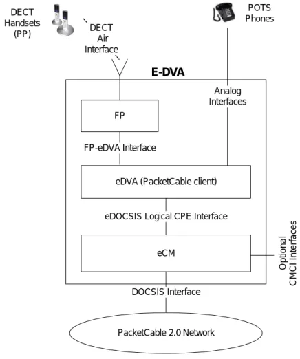
The high-level functional block diagrams of E-DVA and S-DVA are shown in Figure 1 and Figure 2.
eCM
eDVA (PacketCable client) FP
FP-eDVA Interface
eDOCSIS Logical CPE Interface
DOCSIS Interface Analog Interfaces Op ti o n al CM CI I n te rf a c es PacketCable 2.0 Network E-DVA POTS Phones DECT Air Interface DECT Handsets (PP)
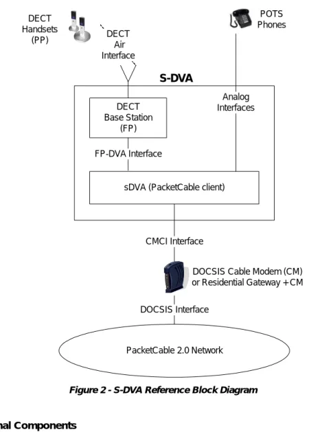
sDVA (PacketCable client) DECT Base Station (FP) FP-DVA Interface CMCI Interface DOCSIS Interface Analog Interfaces S-DVA DECT Air Interface
DOCSIS Cable Modem (CM) or Residential Gateway + CM POTS Phones DECT Handsets (PP) PacketCable 2.0 Network
Figure 2 - S-DVA Reference Block Diagram
5.1.1 Functional Components 5.1.1.1 PP
The DECT handset that is compliant with this specification. It provides the necessary user interface to the HD Voice services.
5.1.1.2 FP
The DECT base station embedded in an E-DVA or S-DVA. It supports one or more PPs, and interacts with eDVA or sDVA in mapping between the DECT and PacketCable signaling protocols.
5.1.1.3 eDVA
The eSAFE in an E-DVA that represents the PacketCable client to the network [eDOCSIS]. It interacts with the FP in mapping between the DECT and PacketCable signaling protocols.
5.1.1.4 sDVA
The logical component inside an S-DVA that represents the PacketCable client to the network. It interacts with the FP in mapping between the DECT and PacketCable signaling protocols.
5.1.1.5 eCM
The embedded DOCSIS cable modem [eDOCSIS]. To support the HD Voice services, eCM needs to be compliant with DOCSIS 1.1 or higher.
5.1.1.6 Cable Modem
The stand-alone cable modem that is used to connect the S-DVA to the PacketCable Network.
5.1.1.7 Residential Gateway
The gateway device that may be used to connect the S-DVA to the PacketCable Network via the cable modem.
5.1.1.8 Analog Phone
The POTS phone that provides the traditional telephony user interface.
5.1.1.9 PacketCable Network
The standard PacketCable compliant SIP network [ARCH-FRM TR]. No special requirements or restrictions are imposed on this network by HD Voice.
5.1.2 Protocol Interfaces
5.1.2.1 eDOCSIS Logical CPE Interface
The standard logical interface between the eSAFE and the eCM [eDOCSIS]. This interface is mandatory for E-DVA.
5.1.2.2 DOCSIS Interface
The standard broadband interface that is compliant with DOCSIS 1.1 or higher. This interface is mandatory for both E-DVA and S-DVA.
5.1.2.3 FP-eDVA Interface
The logical interface between the FP and the eDVA. Depending on the vendor implementation, this interface may or may not correspond to any well-defined physical entity. It simply represents the interactions between the FP and the eDVA, as specified in this document. This interface is vendor-specific.
5.1.2.4 Analog Interface
The standard POTS interface that is compliant with [E-DVA]. This interface is mandatory for both E-DVA and S-DVA.
5.1.2.5 CMCI Interface
The standard CPE interface that is compliant with [CMCI]. This interface is optional for both E-DVA and S-DVA.
5.2
Relationship to other specifications
• PacketCable DECT specification [DECT-HDV]:
The PacketCable DECT specification mandates the relevant parts of the DECT specification for the air interface between the PP and the FP. It also defines requirements for interactions between the FP and the PacketCable client that are embedded in the client device that interfaces to the PacketCable network. All requirements in the
PacketCable DECT specification are mandated for both the E-DVA and the S-DVA.
• PacketCable 24.229 delta specification [PKT 24.229]:
The PacketCable 24.229 delta specification defines SIP and SDP session requirements for the PacketCable UE and network components. This specification is application-agnostic and also includes requirements in the area of security, authentication, NAT/firewall traversal and others. This is also known as the PacketCable core network specification.
• PacketCable Residential SIP Telephony (RST) Feature specification [RSTF]:
The PacketCable Residential SIP Telephony (RST) Feature specification specifies interoperability requirements on the UE and Application Server to implement residential telephony features. All these features need to be supported on the DECT air interface. This specification leverages [PKT 24.229] for the application-independent requirements.
• PacketCable Residential SIP Telephony Embedded Digital Voice Adaptor [E-DVA]:
The PacketCable Residential SIP Telephony Embedded Digital Voice Adaptor specification specifies requirements for a device that integrates the cable modem with a PacketCable Residential SIP Telephony client that supports an analog interface to a POTS phone. It refers to [RSTF] for the feature signaling requirements and defines additional requirements in the areas of codec, security, provisioning, analog interface requirements, and others.
The current specification defines the mapping requirements between DECT and SIP for features specified in the above-mentioned documents. The current specification also defines device requirements for the E-DVA and the S-DVA. These requirements are based on [E-DVA] and enhanced to add requirements for HD voice codecs on the network interface, DECT interface provisioning, NAT traversal, and others.
6 DECT-SIP REQUIREMENTS
This section specifies requirements for DECT to SIP interworking. These requirements apply to the DVA as a whole, and their actual implementation involves the interactions between the FP and the eDVA (for E-DVA) or the sDVA (for S-DVA) shown in Figure 1 and Figure 2.
The DECT-SIP mapping in this section is mainly concerned with the signaling functionality. The DECT-SIP mapping in terms of voice media is straightforward and is considered vendor-specific: it involves the mapping between the voice payloads in the RTP packets on the network side and the DECT voice channel data over the DECT air interface.
6.1
Basic Calls
6.1.1 Inbound Call
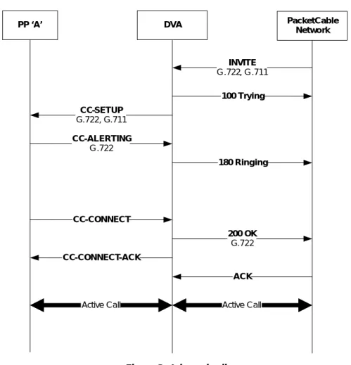
Upon receiving an INVITE for a new call when no other external call is present, the DVA MUST begin call establishment procedures as per [DECT-HDV]. The DVA populates the <<CALLING PARTY NUMBER>> and <<CALLING PARTY NAME>> IEs in the CC-SETUP or IWU-INFO based on the contents of the
P-Asserted-Identity header in the received INVITE, as described in Section 6.3.2. The DVA MUST populate the <<CODEC LIST>> IE in the CC-SETUP and subsequently carry out the codec negotiation with the calling party, according to the codec negotiation requirements in [DECT-HDV].
After the ringing is applied to the analog interface, the DVA MUST send a 180 Ringing message in response to the inbound INVITE.
Upon receiving the CC-CONNECT message from one of the PPs, the DVA MUST send a 200 OK message in response to the inbound INVITE unless the call has already been answered (by another PP or analog interface).
An example call flow for an inbound call is shown in Figure 3. PP ‘A’ PacketCable Network DVA INVITE G.722, G.711 CC-ALERTING G.722 CC-SETUP G.722, G.711 100 Trying ACK 180 Ringing CC-CONNECT 200 OK G.722 CC-CONNECT-ACK Active Call Active Call
Figure 3 - Inbound call
6.1.2 Outbound Call
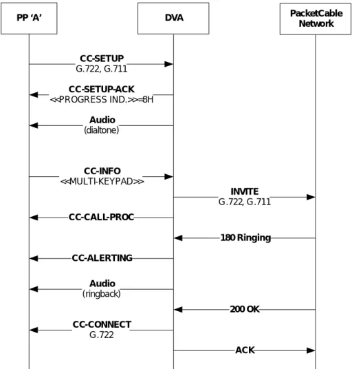
Upon receiving the CC-SETUP message without a <<CALLED PARTY NUMBER>> IE that results in DVA transition to off-hook status as per [DECT-HDV], the DVA MUST follow the procedures in [DECT-HDV] for outgoing call. This involves opening of the U plane with the CC-SETUP-ACK and presenting a dial tone to the user. This is referred to as overlap sending in [EN 300 444] and [DECT-HDV].
The PP sends dialed digits within <<KEYPAD>> or <<MULTI-KEYPAD>> IEs in one or more CC-INFO
messages as specified in [DECT-HDV]. When the digits are being received, the DVA MUST apply the digit map to the received dial string as defined in Section 6.2.1 and follow the defined digit map action. Normally, the action is to send an INVITE towards the network. In this case, the DVA MUST format the INVITE as per [RSTF].
Upon the receipt of 180 Ringing from the network, the DVA MUST send a CC-ALERTING message to the PP. The DVA MUST forward a ring back tone to the PP as in-band media.
Upon the receipt of 200 OK from the network, the DVA MUST send a CC-CONNECT message to the PP. If the remote end point is busy and cannot accept another call, the DVA receives a 486 Busy Here response to the outbound INVITE. In this case, the DVA MUST play a busy tone to the PP as in-band media.
An example call flow for an outbound call with overlap sending is shown in Figure 4. PP ‘A’ PacketCable Network DVA 180 Ringing INVITE G.722, G.711 CC-SETUP G.722, G.711 CC-SETUP-ACK <<PROGRESS IND.>>=8H Audio (dialtone) CC-INFO <<MULTI-KEYPAD>> CC-CALL-PROC CC-ALERTING Audio (ringback) 200 OK CC-CONNECT G.722 ACK
Figure 4 - Outbound call with overlap sending
6.1.3 PP initiated Call Release
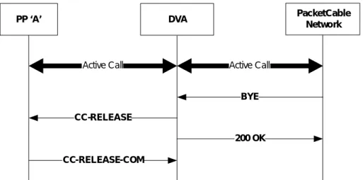
Upon receipt of a CC-RELEASE from the PP that results in DVA transition to on-hook state as specified in [DECT-HDV], the DVA MUST send a BYE towards to the network as specified in [RSTF].
The DVA MUST respond to the CC-RELEASE with a CC-RELEASE-COM to the PP as specified in [DECT-HDV].
An example call flow for a PP initiated call release is shown in Figure 5. PP ‘A’ Active Call PacketCable Network DVA 200 OK CC-RELEASE BYE CC-RELEASE-COM Active Call
Figure 5 - PP initiated call release
6.1.4 Remote endpoint initiated Call Release
Upon receipt of a BYE message from the network for an active external call, the DVA MUST initiate call release procedures by sending a CC-RELEASE message to each of the PPs currently involved in that call as specified in [DECT-HDV].
An example call flow for a remote endpoint initiated call release is shown in Figure 6. PP ‘A’ Active Call PacketCable Network DVA BYE CC-RELEASE-COM 200 OK CC-RELEASE Active Call
Figure 6 - Remote endpoint initiated call release
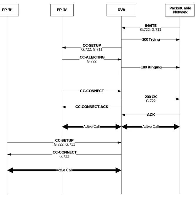
6.1.5 Barge into Existing External Call
A PP is automatically bridged into an existing external call between another PP and the remote PacketCable endpoint if the DVA has been configured for automatic barge-in as specified in [DECT-HDV]. The barge-in does not result in any signaling towards the PacketCable network and is handled locally on the DVA.
An example call flow for a barge-in scenario is shown in Figure 7. In this example, the PP 'A' is already involved in an external call. The PP 'B' goes off-hook, resulting in automatic barge-in. The DVA performs the media mixing function.
PP ‘A’ PacketCable Network DVA INVITE G.722, G.711 CC-ALERTING G.722 CC-SETUP G.722, G.711 100 Trying ACK 180 Ringing CC-CONNECT 200 OK G.722 CC-CONNECT-ACK Active Call Active Call PP ‘B’ CC-SETUP G.722, G.711 CC-CONNECT G.722 Active Call
Figure 7 - Barge into existing external call
6.2
Common Feature Functions
The PacketCable telephony features are based on a few shared common functions. The DECT interactions for these functions are specified below.
6.2.1 Digit Maps
Digit maps are provisioned on the DVA to inform it about how digits entered on the PP by the user should be interpreted. A digit map is an ordered set of regular expressions combined with some special tokens that represent actions to be carried out by the DVA when a regular expression is matched.
The PP forwards the user-entered digits to the DVA by following the corresponding procedure defined in
6.2.2 Vertical Service Codes
Vertical service codes (VSC) are dialed digit strings used to represent feature invocations. They are sometimes referred to as star codes or feature activation codes. A feature invocation is feature activation, feature deactivation, feature programming, or feature instance. A VSC does not have to begin with a star, nor is it restricted to a 3-digit string such as "*69." The actual digits that make up a VSC are defined by the digit map. The digit map also defines whether the VSC is processed by the DVA or forwarded to the network.
The PP forwards a VSC as user-entered digits to the FP in the DVA by following the corresponding procedure defined in [EN 300 444]. As the VSC digits are being received from the PP, the DVA applies the provisioned digit map to the digits as specified in Section 6.2.1.
6.2.3 Held Media
There are a number of service capabilities that make use of a call state that is 'held' and, as a result, also require that any active bi-directional media stream also be held. [RSTF] specifies media hold and retrieval in terms of SDP offer-answer procedures.
When service logic requires that the network media be held, the DVA MUST hold the media stream from it to the network by use of the held media procedures defined in [RSTF].
When service logic requires that currently held network media be resumed; the DVA MUST retrieve the media stream from it to the network by use of the media retrieval procedures defined in [RSTF].
6.2.4 Announcements
Users are alerted to some network conditions or states by announcements. Announcements could be informational tones or messages played to end users in response to events that occur in the network. An announcement could be stored or generated locally by the DVA to the end user, or could be received by the DVA as an audio from a network-based media server.
The DVA MUST follow [RSTF] in creating announcements. The DVA MUST send the created announcement to the PP as in-band media.
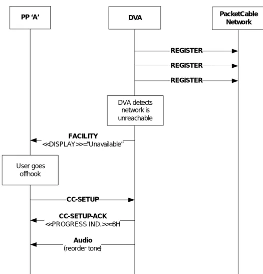
6.2.5 In-Service and Out-of-Service States
[DECT-HDV] specifies the procedure to proactively advertise to the DECT handsets that network connectivity has been lost. This procedure allows a message to be displayed on the handsets to inform the user that the network is down before the user goes off-hook.
As specified in [RSTF], the DVA is required to inhibit dial tone presentation to the user going off-hook when the STUN server can not be reached but network connectivity is present. The DVA is required to present a reorder tone to the user going off-hook when network connectivity has been lost (the last REGISTER transaction has failed). If the DVA receives a CC-SETUP message from the PP to initiate an external call after the most recent registration attempt failed, the DVA MUST complete the CC-SETUP transaction normally and present a reorder tone to the PP. If the DVA receives a CC-SETUP message from the PP to initiate an external call after the most recent registration attempt succeeded but the most recent STUN transaction failed, the DVA MUST complete the CC-SETUP transaction normally and refrain from presenting dial tone to the user.
In both the cases, the DVA MUST inform the PP user about this condition by following the procedures in [DECT-HDV] for Service Status.
PP ‘A’ PacketCable Network DVA REGISTER FACILITY <<DISPLAY>>=”Unavailable” CC-SETUP REGISTER REGISTER CC-SETUP-ACK <<PROGRESS IND.>>=8H Audio (reorder tone) DVA detects network is unreachable User goes offhook
Figure 8 - Loss of Network Connectivity produces reorder tone
6.2.6 Early Media
Early media is the media exchanged before the call is fully established. The media stream may be one-way or two-way.
The usual example of one-way media is the ring back when the DECT PP A calls network hosted UE B and A hears ring back tone from B via early media even before the network side SIP dialog is confirmed (which happens when B answers the call). An example of two-way media is PIN entry: the DECT PP A calls network hosted UE B that has Call Blocking services, and A is connected to a media server for collection of a PIN. The media stream is
bi-directional; one stream to the media server for PIN digit reception, the other from the media server to request the entry of the PIN. In both examples the call is not considered established as the SIP dialog initiating transaction is not complete.
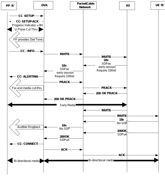
As specified in [DECT-HDV], the DVA is required to open the U-plane as part of the CC-SETUP transaction. As the U-Plane is connected immediately and prior to reception of any SIP response by the DVA, the application of audible ring back and any network-provided early media is entirely handled by the DVA with no additional signaling required on the DECT interface.
The DVA performs the following actions upon reception of SIP responses during call setup:
Figure 9 shows a representative call flow for the application of early media originating from the PacketCable network. It illustrates the procedural requirements detailed for the DVA.
Figure 9 - Early Media
6.2.7 No Answer Timeout
No Answer Timeout prevents an incoming call from causing the application of power-ringing indefinitely. Specifically, No Answer Timeout causes an inbound call to be rejected once the call has been offered and unanswered for a time exceeding the No Answer timer duration.
The behavior of this feature is triggered by timer expiration on the DVA. Upon expiration of the timer, the DVA
PP ‘A’ AS CC - SETUP 18x SDPas early session Require: 100rel U Plane Cut Thru
INVITE PacketCable Network DVA INVITE 18x SDPas early session Require: 100rel CC - SETUP - ACK Progress Indicator = 8H UE ‘B’ PRACK PRACK 200 OK PRACK 200 OK PRACK Early Media INVITE 18x No SDP 18x No SDP INVITE 200 OK SDPue 200 OK SDPue CC-CONNECT ACK ACK
FP provides Dial Tone
Far-end media cut-thru
Audible Ringback
CC - ALERTING CC - INFO
Bi-directional media Bi-directional media
the DVA MUST also terminate the call over the DECT interface following procedures in [EN 300 444] and [DECT-HDV].
6.3
Residential SIP Telephony Features
This section specifies DECT to SIP mapping requirements for the telephony features specified in [RSTF]. 6.3.1 Features with no additional DECT-SIP mapping requirement
The following [RSTF] features either do not involve the mapping between SIP messages and DECT messages, or the involved mapping is already covered by other sections of this specification, such as Section 6.1 and Section 6.2.
• Caller ID Per-Line Blocking
• Caller ID Per-Call Blocking (CIDS-Suppression)
• Caller ID Per-Call Delivery (CIDS-Delivery)
• Caller ID with Call Waiting (CIDCW)
• Anonymous Call Rejection
• Call Forwarding Don't Answer
• Call Forwarding on Busy Line
• Remote Activation of Call Forwarding
• Call Forwarding to Voice Mail
• Outbound Call Blocking
• Solicitor Blocking
• Collect Call blocking
• Operator Services
• Subscriber Programmable PIN
• Speed Dialing
• Customer-Originated Call Trace
• Screen List Editing 6.3.2 Caller ID
Caller ID Display is a feature that allows a subscriber to see who is calling before answering the call. Caller ID Display consists of two sub-features: Calling Number Display (CND) and Calling Name Display (CNAMD). For an incoming call, the Caller ID information, if available, is carried in the P-Asserted-ID header of the INVITE request. The P-Asserted-ID may not be available if the caller has requested the call to be anonymous. The DVA can convey the Caller ID information as <<CALLING PARTY NUMBER>> and <<CALLING PARTY NAME>> in the CC-SETUP or IWU-INFO message sent to the PP as specified in [DECT-HDV]. If the call time is available, the DVA sends the call time as a <<TIME-DATE>> IE in an IWU-INFO message per [DECT-HDV].
If the CND feature is activated, the DVA MUST set <<CALLING PARTY NUMBER> by following the requirements in [RSTF] for constructing the calling party number to be displayed.
If the CNAMD feature is activated, the DVA MUST set <<CALLING PARTY NAME>> by following the requirements in [RSTF] for constructing the calling party name to be displayed.
6.3.3 Call Forwarding Variable
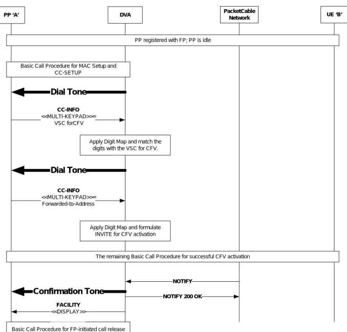
Call Forwarding Variable (CFV) is a feature that allows the subscriber to activate forwarding of all calls that go to the subscriber's public identity to another location. The forward-to address can be provided through subscriber interaction with the CFV feature, or the network operator can configure the forward-to address for a subscriber. With CFV, the forwarding happens before the DVA alerts (rings) the called party, so the forwarded public identity has no opportunity to answer the call.
When CFV is successfully activated or deactivated, the DVA MUST notify the subscriber by generating and transmitting an in-band confirmation tone to the PP on which the feature is being activated or deactivated. With CFV active, upon receiving a SIP NOTIFY message from the network about newly forwarded calls, the DVA MUST:
• Apply a ring splash to the PP, by following the ring generation requirements in [DECT-HDV].
• Send a FACILITY message to the PP with a <<DISPLAY>> IE that conveys the provisioned display string for newly forwarded calls defined in Table 1, if it is not a null string.
If the special conditions dial-tone is enabled for the subscriber with the CFV feature activated, then each time a subscriber with CFV activated goes off-hook, the DVA MUST play a locally-generated special conditions dial-tone as a reminder that CFV is active, by following the tone generation requirements in [DECT-HDV]. In this case, the DVA MUST also send a FACILITY message to the off-hook PP with a <<DISPLAY>> IE that conveys the provisioned display string for activation status defined in Table 1, if it is not a null string. If there are other active features that require their statuses to be conveyed to the PP as well, the DVA MUST concatenate all status-display strings (with appropriate spaces) and send the resulted string with a <<DISPLAY>> IE in a single FACILITY message.
Table 1 - CFV Display Strings
Data Type Persistence Default Value Range Scope Provisioning Requirement CFV display string for
newly forwarded calls
String Volatile Null string N/A Per FP Mandatory Read-Write CFV display string for
activation status
String Volatile Null string N/A Per FP Mandatory Read-Write
An example call flow for feature activation is shown in Figure 10. PP ‘A’ PacketCable UE ‘B’ Network CC-INFO <<MULTI-KEYPAD>>= VSC forCFV
PP registered with FP; PP is idle DVA
Basic Call Procedure for MAC Setup and CC-SETUP
The remaining Basic Call Procedure for successful CFV activation Apply Digit Map and match the
digits with the VSC for CFV.
Dial Tone
Dial Tone
CC-INFO <<MULTI-KEYPAD>>=
Forwarded-to-Address
Apply Digit Map and formulate INVITE for CFV activation
NOTIFY NOTIFY 200 OK
Confirmation Tone
Basic Call Procedure for FP-initiated call release FACILITY
<<DISPLAY>>
An example call flow for status change notification is shown in Figure 11.
PP ‘A’ PacketCable UE ‘B’
Network
PP registered with FP; PP is idle or active
DVA NOTIFY NOTIFY 200 OK FACILITY <<DISPLAY>> = CFV execution status
Figure 11 - CFV Status Change
6.3.4 Selective Call Forwarding
Selective Call Forwarding (SCF) is an incoming call management feature that allows the subscriber to define a special list of addresses and remote addresses. Incoming calls from public identities that are on the list are forwarded to the remote address. With SCF, the forwarding happens immediately and the original target public identity has no opportunity to answer the call.
With SCF active, upon receipt of a SIP NOTIFY message from the network about newly forwarded calls, the DVA MUST:
• Apply a locally-generated ring splash to the PP, by following the ring generation requirements in [DECT-HDV].
• Send a FACILITY message to the PP with a <<DISPLAY>> IE that conveys the provisioned SCF display string for newly forwarded calls defined in Table 2, if it is not a null string.
Table 2 - SCF Display String
Data Type Persistence Default
Value Range Scope
Provisioning Requirement
SCF display string for newly forwarded calls
String Volatile Null String N/A Per FP Mandatory
Read-Write
6.3.5 Hook-Flash Processing
Several telephony features allow the subscriber to use hook-flash to trigger feature logic. The hook-flash in turn prompts the PP to send to the DVA a CC-INFO message with a <<KEYPAD>> or <<MULTI-KEYPAD>> IE that has a value for Register Recall, as described in [DECT-HDV].
The DVA interprets the Register Recall indication as a hook-flash as described in [DECT-HDV], and MUST follow [RSTF] for the requirements related to hook-flash processing.
6.3.6 Call Waiting
The Call Waiting (CW) feature provides the subscriber with the ability to detect an incoming call while in an existing call, and to answer that call by hook-flashing, putting the existing call on hold.
tone, the DVA MUST apply the tone to the PP, by following the tone generation procedure in [DECT-HDV]. The DVA follows Section 6.3.2 for the mapping requirements for Caller ID with Call Waiting.
If multiple PPs are involved in an existing call when another call comes in, the DVA MUST apply the call waiting tone and the caller ID to all such PPs. In addition, the DVA MUST apply hook-flash signals from any of these PPs to the CW procedure. This allows the CW procedure to be controlled from any of these PPs.
An example call flow for Call Waiting is shown in Figure 12.
PP ‘A’ PacketCable UE ‘B’
Network
CC-INFO
<<CALLING PARTY NUMBERr>> = Number for ‘C’ <<CALLING PARTY NAME>>
= NAME for ‘C’
A stable call is established between ‘A’ and ‘B’
In-Band Call Waiting Tone
DVA UE ‘C’
INVITE ReqURI = ‘A’ INVITE
ReqURI = ‘A’
Hook flash received from the user
CC-INFO <<MULTI-KEYPAD>>
= Register Recall
RST procedure for holding ‘B’ and accepting ‘C’ Media: ‘A’ - ‘B’
Media: ‘A’ - ‘C’ IWU-INFO
<<TIME-DATE>>
Figure 12 - Call Waiting
6.3.7 Call Hold
During an active call, the Call Hold feature allows the user to place the call on hold, without ending the call. The call is kept on hold, allowing the user to initiate other calls without impacting the call state of the held call.
Activation of Call Hold is achieved by the user entering a hook-flash, receiving recall dial tone and dialing the defined VSC for Call Hold. Similarly de-activation (retrieval) of a call previously held by this mechanism is achieved by the user entering a hook-flash followed by the same VSC (i.e., the VSC acts as a toggle). The
requirements for handling a hook-flash are defined in Section 6.3.5. The requirements for handling the entry of the VSC are defined in Section 6.2.2.
On reception of the VSC for Call Hold for a currently active call, the DVA UE MUST hold the network media using the mechanisms defined in Section 6.2.3. On reception of the VSC for Call Hold for a currently held call, the DVA MUST retrieve the network media using the mechanisms defined in Section 6.2.3.
6.3.8 Call Transfer
Call Transfer is the transfer of one caller (the transferee) to another party (the transfer-to party), in which the transfer is initiated by the originator of the second call (the transferor). There are two common varieties of Call Transfer - consultative and blind. These are defined in [RSTF] in terms of the state of the second call: if the call is unanswered before completion of the transfer sequence, the transfer is considered blind; otherwise, it is consultative.
The DVA follows the procedures in [RSTF] for handling Call Transfer. User interaction with the service logic is via the use of hook-flash to both enable the initiation of a second call leg when on an active call, and subsequently to transfer the two remote parties. The requirements for handling a hook-flash are defined in Section 6.3.5.
6.3.8.1 Scenario 1: DECT PP Initiated Transfer
A DECT PP that is already part of an existing two-party call upon detection of hook-flash issues a CC-INFO as defined in Section 6.3.5. The DVA SHOULD hold the currently active call using the procedures defined in Section 6.2.3. The DVA then provides dial-tone to the PP and MUST follow basic call procedures (Section 6.1) to initiate a second call.
Completion of the transfer occurs when the PP goes on-hook and issues a CC-RELEASE to the FP. If the DECT PP goes on-hook while the second call attempt is still alerting, then this is termed a blind transfer. If the DECT PP goes on-hook after the second call attempt has been established, then this is termed a consultative transfer. On detection of the CC-RELEASE on the second call attempt, the DVA MUST make use of the procedures defined in [RSTF] to complete the call transfer via use of the REFER method. On reception of a NOTIFY indicating that the transfer was successful, the DVA MUST release all call legs on the PacketCable network.
Figure 13 shows a representative flow for the case where the transferor is a DECT PP: UE ‘B’ PP ‘A’ Core UE ‘C’ Active Call #1 CC-RELEASE 200 OK/ ACK DVA Active Call #2 Active Call Media Active Call #1 Active Call #2 AS
PP ‘A’ initiates call to to UE ‘C’; hold Call #1 leg. INVITE/ 200 OK.ACK SDP a=inactive INVITE/ 200 OK.ACK INVITE/ 200 OK.ACK SDP a=inactive INVITE/ 200 OK.ACK REFER/202
Refer-To: C?Replaces A-C
REFER/202 Refer-To: C?Replaces A -C REFER/202 Refer-To: AS REFER/202 Refer-To: AS INVITE ReqURI = AS INVITE ReqURI = AS INVITE ReqURI = C
Replaces A-C INVITE
ReqURI = C Replaces A -C 200 OK/ ACK 200 OK/ ACK 200 OK/ ACK NOTIFY/ 200 OK NOTIFY/ 200 OK NOTIFY/ 200 OK NOTIFY/200 OK CC-RELEASE-COM BYE/ 200 OK BYE/ 200 OK BYE/ 200 OK BYE/ 200 OK Release Call #1 Active Call Media
6.3.8.2 Scenario 2: Remote Endpoint Initiated Transfer
The DVA that receives a REFER in accordance with [RSTF] follows the procedures defined therein for completion of Call Transfer. The DVA that receives an INVITE containing a Replaces header in accordance with [RSTF] follows the procedures defined therein for handling of the INVITE.
The DVA MAY make use of the CC-INFO message with <<CALLING PARTY NUMBER>> and <<CALLING PARTY NAME>> IEs to update the connected or calling party information presented to DECT PPs involved in the call transfer as either transferee or transfer-to. Updated calling or connected party information is received in a P-Asserted-Identity header either in an INVITE (Replaces) received by the DVA or in the 200 OK to an INVITE set by the DVA as a result of the reception of a REFER.
Figure 14 shows a representative flow for the case where the transferor is in the PacketCable network. Core AS UE A PP “B’ Active Call #1 202 REFER
Refer-To: C?Replaces A-C TargetDialog: A-B REFER Refer-To: AS 202 REFER Refer-To: AS 202
Active Call Media
DVA
CC-INFO
Active Call #2
REFER
Ref.-To: C?Repl. A-C Target-Dialog: A-B 202 INVITE AS INVITE AS INVITE RequestURI C Replaces A-C INVITE Replaces A-C 200 OK/ACK 200 OK/ ACK 200 OK/ ACK 200 OK/ ACK NOTIFY/200 OK NOTIFY/ 200 OK NOTIFY/ 200 OK NOTIFY/ 200 OK BYE AtoB/ 200 OK BYE AtoB/ 200 OK BYE AtoC/ 200 OK BYE AtoC/ 200 OK
Active Call Media
UE ‘C’
A already has call #1 on hold, goes on-hook after successful completed consult leg to C (call
#2). REFER is sent out of dialog
6.3.8.3 Message Mapping
This mapping applies to the reception at the DVA of an INVITE containing a Replaces header identifying an existing SIP context on the DVA. Media bridging will occur at the device. However, the DVA MAY map the P-Asserted-Identity in the INVITE to a <<CALLING PARTY NUMBER>> and <<CALLING PARTY NAME>> IEs in the CC-INFO message to the DECT PP that is part of the existing call identified by the Replaces header. Similarly, on reception of a 200 OK for an INVITE sent by a DVA while handling the reception of a REFER, the DVA MAY map the 200 OK to a CC-INFO to the DECT PP that is part of the call dialog associated with the REFER.
6.3.9 Three-Way Calling
Three-Way Calling (3WC) allows a subscriber to add a third party to an existing two-party active call without operator assistance.
The 3WC logic is provided by the DVA, by following the requirements in [RSTF]. While in a stable call, the subscriber uses hook-flash to initiate the call to the third party. The DVA follows requirements in Section 6.3.5 for hook-flash processing. The DVA MUST apply a locally-generated dial tone to the PP, by following the tone generation procedure in [DECT-HDV]. After the dial tone is applied, the DVA follows [RSTF] for processing the third-party address entered by the subscriber and for initiating the call to the third party. Upon connecting to the third party, the subscriber performs hook-flash again to enter the 3-way call.
Figure 15 shows a representative flow for 3WC. PP ‘A’ PacketCable UE ‘B’ Network CC-INFO <<MULTI-KEYPAD>> = Address for ‘C’
A stable call is established between ‘A’ and ‘B’
In-Band Dial Tone
DVA UE ‘C’
Hook flash received from the user
CC-INFO <<MULTI-KEYPAD>>
= Register Recall
RST procedure for initiating call with “C” Media: ‘A’ - ‘B’
Media: ‘A’ - ‘C’
RST procedure for holding ‘B’
Dialed digits received from the user
Hook flash received from the user
CC-INFO <<MULTI-KEYPAD>>
= Register Recall
RST procedure for taking ‘B’ out of hold
Media: ‘A’, ‘B’, ‘C’
Media: ‘A’, ‘B’, ‘C’ Figure 15 - Three Way Call
6.3.10 Call History
Call History consists of two discrete services, Automatic Recall and Automatic Callback.
The Automatic Recall (AR) service allows a user to automatically return a call to the last calling address, i.e., the entity that terminated a call to this UE, whether the call was answered or not. The AR service works even when the last call received by the user was anonymous.
Activation of either AC or AR is achieved by the user dialing the defined VSC for the requested service; the requirements for handling the entry of the VSC are defined in Section 6.2.2.
On reception of the VSC for AC or AR, the DVA follows the procedures defined in [RSTF] for initiating an AC or AR call attempt and the subsequent handling of SIP responses from the network.
If the DVA receives a 486 User Busy response to the AC or AR call attempt, then the DVA MUST NOT render any call failure tone or announcement to the PP; instead, the DVA follows the procedures defined in [RSTF] for subscription to the dialog state of the target of the call attempt.
The DVA makes use of Third Party Call Control (3PCC) techniques to connect the PP and the AC or AR target once the AC or AR target becomes idle as defined below:
• If the DVA receives a NOTIFY message from the network on the dialog created by the subscription to the dialog event package indicating that the AC or AR target is now idle, and the PP that initiated the AC or AR attempt is also idle, then the DVA MUST send a CC-SETUP to the PP including a <<SIGNAL>> IE populated as defined in [DECT-HDV] to provide special alerting at the PP.
• The DVA MUST start a timer for the special alerting duration and handle timer expiry as defined in [RSTF].
• Upon reception at the DVA of a CC-CONNECT indicating that the PP has answered the call attempt to it, the DVA MUST send an INVITE to the target of the AC or AR attempt as defined in [RSTF].
• The DVA, on reception of an 18x progress message from the network with no SDP, MUST provide local ring back tone to the PP.
• The DVA, on reception of an 18x progress message from the network with SDP, MUST cut-through the far end media to the PP.
• Once the AC or AR target answers the call attempt, the DVA MUST NOT map the SIP 200 OK to a
CC-CONNECT as per basic call procedures (Section 6.1); instead, the DVA MUST cut-through far end media if it has not done so already.
Figure 16 shows a representative call flow for the invocation of Automatic Recall. Note that Automatic Callback exhibits the same flow, except that the Request URI in the initial INVITE will be that of the last party called.
PP ‘A’ Core UE ‘B’
Incoming Call Attempt
DVA
CC-SETUP
INVITE
ReqURI = Last Caller Incoming Call Takedown
No answer at PP, either expiration of ringing timer or caller hangs up
INVITE
ReqURI = Last Caller
486 User Busy 486 User Busy
ACK
Assume UE ‘B’ is engaged in another call and ignores the incoming call in wait
ACK
E-DVA knows this is a response to an AR originated INVITE and so invokes AR
procedures as per RSTF SUBSCRIBE Event = dialog SUBSCRIBE 200 OK 200 OK NOTIFY Dialog state NOTIFY 200 OK 200 OK
E-DVA uses RSTF to render a “delayed processing” announcement which can either be network hosted or locally available; either way the U-plane on the DECT side is connected so that the announcement is audible.
CC-RELEASE CC-RELEASE-COM
CC-INFO
<<MULTI-KEYPAD>> = VSC
CC-SETUP-ACK
Figure 16 - Auto Recall - Invocation
Figure 17 shows a representative call flow for the continuation of an Automatic Recall attempt once the target becomes idle. Note again that Automatic Callback exhibits the same flow except that the Request URI in the INVITE will be that of the AC target.
PP ‘A’ DVA Core UE ‘B’
200 OK
If the AR originator is on-hook apply special ringing; on off-hook initiate the AR call attempt
NOTIFY
UE Dialog State Notify State = Terminated Active dialog event subscription for an AC or AR attempt
200 OK
UE ‘B’ goes back on hook
CC-SETUP
<<SIGNAL>> = Special Alert
CC-ALERT CC-CONNECT INVITE ReqURI AR Target INVITE 180 Ringing 180 Ringing 200 OK 200 OK ACK ACK
Apply Audible Ringback
CC-CONNECT-ACK
Cut-thru farend media U-Plane Cut-thru
NOTIFY
6.3.11 Emergency Services
The Emergency Services allow the subscriber to initiate emergency calls from a PP. The detailed description and general assumptions for the emergency-call support on a DVA are provided in [RSTF].
With the PP registered with the DVA, the subscriber makes an emergency call by entering the digit string designated for the emergency services. The DVA applies the digit map to process and recognize the designated digit string, and subsequently to carry out the emergency call procedure as specified in [RSTF]. The DECT-SIP mapping
requirements for digit map processing are provided in Section 6.2.1.
The DECT setup procedure for an emergency call is the same as that for a basic call, which is described in Section 6.1. As specified in [RSTF], there are several special requirements related to the maintenance of an emergency call. In particular, when the subscriber goes on-hook during an emergency call, the DVA performs Network Hold on the call. The DECT-SIP mapping requirements for Network Hold are provided in Section 6.3.7.
6.3.12 Do Not Disturb
The Do-Not-Disturb (DND) feature allows the subscriber to put a DVA into a mode in which the DVA does not send an alert when a call is presented.
The subscriber can activate or deactivate the DND feature by entering a Vertical Service Code (VSC). In this case, the DVA follows Section 6.2.2 for the DECT-SIP mapping requirements associated with VSC processing.
Upon completion of activation or deactivation operation, the DVA is notified by the network about the status change of the feature. When the NOTIFY message is received, the DVA MUST apply the confirmation indicator (a tone or an announcement) to the PP as in-band media.
With the DND feature active and upon detection of off-hook condition, the DVA MUST follow the [DECT-HDV] tone generation procedures to apply a recall dial tone to alert the subscriber that the DND is still active, as described in [RSTF]. In this case, the DVA MUST send a FACILITY message to the PP with a <<DISPLAY>> IE that conveys the provisioned display string defined in Table 3, if it is not a null string. If there are other active features that require their statuses to be conveyed to the PP as well, the DVA MUST concatenate all status-display strings (with appropriate spaces) and send the resulting string with a <<DISPLAY>> IE in a single FACILITY message.
Table 3 - DND Display String
Data Type Persistence Default
Value Range Scope
Provisioning Requirement
DND display string for activation status String Volatile Null string N/A Per FP Mandatory
Read-Write
6.3.13 Distinctive Alerting
The Distinctive Alerting (DA) feature allows different alerting patterns to be rendered to the subscriber on a per-call basis. The selection of a particular alerting pattern for a given incoming call is determined by the DA application server in the terminating network.
The subscriber can program the DA feature by entering a Vertical Service Code (VSC). In this case, the DVA follows Section 6.2.2 for the DECT-SIP mapping requirements associated with VSC processing.
Upon receiving an incoming INVITE from the network, the DVA determines the alert signal to be applied to the subscriber by mapping the Alert-Info header in the INVITE message, as described in [RSTF]. If the resulting alert signal is a ringing signal, the DVA MUST follow [DECT-HDV] in applying the ringing signal to the PP. 6.3.14 Message Waiting Indicators
Message Waiting Indicators (MWI) are used by the DVA to alert the PP that the status of a message account associated with the subscriber is changed. Once received, the MWI is presented by the PP to the subscriber as a visual signal and/or an audible signal.
Upon receiving a NOTIFY message for the MWI event, the DVA MUST send a FACILITY message to the PP with an <<EVENTS-NOTIFICATION>> IE that indicates voice message waiting, as specified in [DECT-HDV]. The DVA MUST set the Event Multiplicity value in the <<EVENTS-NOTIFICATION>> IE to be the sum of the new message count and the old message count indicated in the SIP NOTIFY message.
Figure 18 shows a representative call flow for MWI.
PP ‘A’ PacketCable UE ‘B’
Network
PP registered with FP; PP is idle or active DVA
NOTIFY MWI event: new & old msg counts, new & old urgent msg counts FACILITY
<<EVENTS NOTIFICATION>>: Event Type = message waiting, Event Sub Type = Voice Message Event Multiplicity =
new msg count + old msg count
NOTIFY 200 OK Render the MWI to
the user
‘B’ leaves a voice message for ‘A’
Figure 18 - Message Waiting Indicator
6.3.15 Network-Based Call Screening
Network-Based Call Screening (NBCS) allows the user to hear the prompts from the voice mail server (VMS) and the voice message of a caller as the message is being recorded by the VMS. The user has the option of answering the call while the message is being played; in this case, the user will be connected with the caller.
The NBCS feature is triggered on the network side by an incoming call if the feature execution of Call Forwarding Don’t Answer (CFDA) or Call Forwarding Variable (CFV defined in Section 6.3.3) requires the call to be forwarded to the VMS.
The DVA follows RST requirements on NBCS for interaction with the PacketCable network as defined in [RSTF] Upon receiving an INVITE that indicates the call is for NBCS per [RSTF], the DVA MUST follow the requirements on FP as specified in [DECT-HDV] for the rendering of the voice mail message to the user. In addition, the DVA MUST NOT trigger alerting on any analog telephony interface. While the voice mail prompts and the caller message are being played out on the PPs, if the FP detects that the user has answered the call per [DECT-HDV], the DVA MUST follow the NBCS signaling requirements in [RSTF] to drop the VMS from the session and to connect the called party with the original caller.
6.3.16 Multi-line Support
The Multi-line feature associates multiple directory numbers (DN) with a HD Voice client device. In particular, it supports the mappings between these DNs and various PPs that are registered with the FP within the client device. Such mappings can be either controlled by the user or provisioned by the operator. An incoming call destined to a DN is delivered to the PPs that are associated with the DN. For an outgoing call, one of the DNs that are associated with the originating PP is selected as the calling address.
As part of the SIP registration process, the DVA registers all the public user identities corresponding to the DNs that are associated with the device.
Upon receiving an incoming INVITE, the DVA MUST follow the Multi-line requirements in [DECT-HDV] for the delivery of the call over the DECT air interface, using the Request URI in the INVITE as the destination DN to determine the targeted PPs. The DVA MUST follow the basic inbound call requirements as per Section 6.1.1 in
For an outbound call, the DVA MUST follow the Multi-line requirements in [DECT-HDV] for the PP-originated call. The DVA MUST follow the basic outbound call requirements as per Section 6.1.2 in performing the DECT-SIP signaling mapping, using the calling party address that corresponds to the origination DN. The origination DN for the call is determined as per [DECT-HDV].
When a call destined to an associated DN is on-going and another INVITE destined to the same DN arrives, the DVA MUST follow the Multi-line requirements in [DECT-HDV] in determining if or not the second incoming call is subject to the call waiting treatment. If the second incoming call is subject to call waiting treatment, the DVA MUST follow call waiting requirements specified in Section 6.3.6.
When providing MWI to the PPs, the DVA follows the corresponding requirements in [DECT-HDV]. Specifically, the DVA includes the line identifier in the MWI event-notification message that notifies the PPs of the pending MWI. For this event-notification message, the DVA MUST map the called DN information in the SIP MWI event-notification message to the line identifier, as per the mapping requirements in [DECT-PROV].
When activating or deactivating a feature by dialing a VSC on a PP as described in Section 6.2.2, the user may precede the VSC dialing with the selection of a line identifier for the activation or deactivation. The PP indicates such user-selected line identifier to the DVA, as described for outbound call in [DECT-HDV]. If no user-selected line identifier is provided, the DVA selects a default line identifier, following the Multi-line requirements for outbound call in [DECT-PROV]. For the outbound VSC-bearing INVITE, the DVA MUST use the calling-party address that corresponds to the origination DN determined according to [DECT-HDV].
Annex A Device Requirements (Normative)
A.1
Embedded Device (E-DVA) Requirements
The E-DVA MUST conform to the DVA requirements in this specification.
The E-DVA MUST conform to [DECT-HDV] for requirements pertaining to the DECT interface and its interactions with the analog phone interface.
The E-DVA MUST conform to the requirements in [E-DVA] with the following additions:
• For codecs over the PacketCable network, the E-DVA MUST support G.722 in addition to G.711.
• The E-DVA MUST support the additional provisioning requirements in [DECT-PROV].
For loopback testing, the loopback points within the E-DVA are the same for both the DECT interface and the analog interface. Therefore, these loopback tests do not reach over to the PP.
A.2
Standalone Device (S-DVA) Requirements
The S-DVA MUST conform to the E-DVA requirements in Section A.1, with the following exception - for NAT/Firewall traversal, the S-DVA MUST support the SIP Outbound and the ICE methodology described in [PKT 24.229].
Appendix I
Acknowledgements
The PacketCable team wishes to recognize the following individuals for their significant involvement and contributions to this specification (ordered alphabetically by company name and individual's first names in each company):
Billy Hare, Arris
Eugene Nechamkin, Broadcom Gordon Li, Broadcom (Lead Editor) Effi Shiri, DSP Group
Dave Ellis, Motorola Jerry Mahler, Motorola Mark Trayer, Samsung Oliver Maiwald, SiTel
The following CableLabs staff is thanked for their indirect contributions that helped us improve this specification in various ways: David Hancock, Eduardo Cardona, Jean-Francois Mulé, Kevin Johns and Stuart Hoggan.
Appendix II
Revision History
The following Engineering Change Notice were incorporated into PKT-SP-DECT-SIP-I02-090917.
ECN Date
Accepted
Summary
DECT-SIP-N-09.0568-1 6/22/09 Add support for the Network based call screening (NBCS) feature DECT-SIP-N-09.0581-2 6/22/099 Add support for Multiline feature