ISSCC 2004 / SESSION 17 / MEMS AND SENSORS / 17.4
17.4
An Ultra-Low Energy Microcontroller for
Smart Dust Wireless Sensor Networks
Brett A. Warneke, Kristofer S.J. Pister University of California, Berkeley, CA
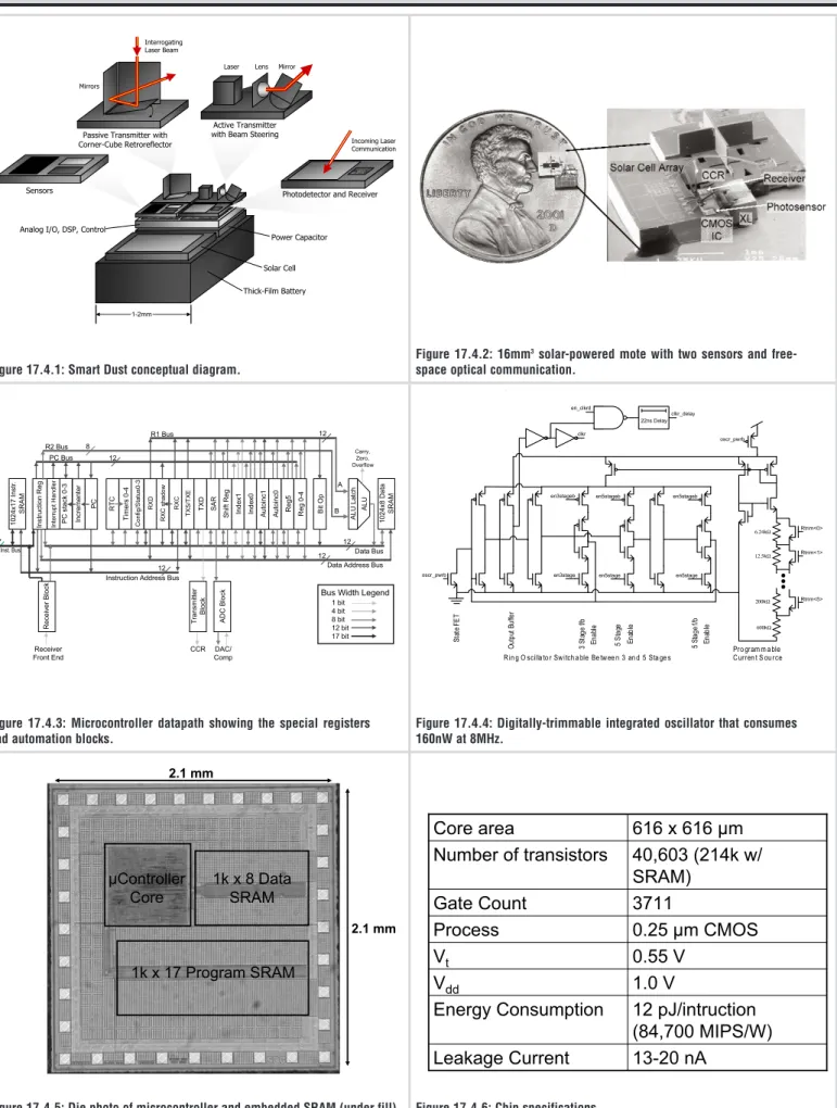
The rapid decreases in power consumption, size and cost along with dramatic increases in performance of communication, sens-ing and computation have led to the development of Smart Dust – millimeter-scale autonomous systems that form the basis of massive distributed wireless sensor networks [1]. Smart Dust motes contain digital control and processing, one or more sen-sors, sensor interface circuits including an ADC, wireless com-munication, and energy storage/power source (Fig. 17.4.1) – inte-grating a complete, complex system into a millimeter-scale vol-ume. Sample applications include inventory control, smart office spaces, fingertip accelerometer virtual keyboards, defense net-works that could be rapidly deployed by unmanned aerial vehi-cles (UAV), nodes that track the movements of birds, small ani-mals, and even insects, and environmental networks that moni-tor conditions affecting crops and livestock.
Because power and energy directly relate to volume, minimizing these quantities is critical for miniaturizing wireless sensor nodes. An ultra-low energy microcontroller designed specifically for integration in Smart Dust motes is developed and consumes less than 12pJ/instruction when executing general instructions and includes special architectural features to reduce the energy consumption of common tasks.
Figure 17.4.2 shows the 16mm3system [2] for which the micro-controller is developed. It is composed of a micromachined cor-ner-cube retroreflector (CCR) [3], an SOI solar cell array, an SOI micromachined capacitive accelerometer, a photosensor, an inte-grated oscillator, a 69pJ/bit, 1 Mbps optical receiver, a 31pJ/sam-ple ADC [4] and a finite state machine (FSM) controller. The CCR provides passive free-space optical transmission in a one-to-many network topology at a cost of only 16pJ/bit. The FSM allows demonstration of the system components, but is replaced by the microcontroller to provide programmability and greater functionality.
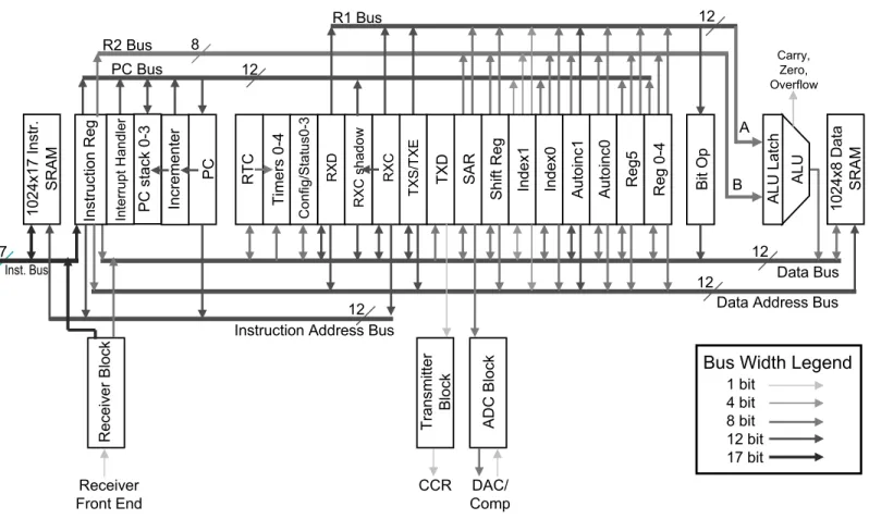
The main low power architectural features [5] of the microcontroller include: highly independent subsystems that maximize the data-path sleep time; component-level clock gating performed in the decoder; processor halt mode with instantaneous oscillator power-cycling; guarded ALU inputs; multiple busses (Fig. 17.4.3); Harvard architecture to take advantage of address and data time correlation and allow separate optimization of data (8b) and instruction (17b) size; load-store RISC; no datapath pipelining because of the hard-ware overhead; decoder pipelining using two delayed clocks; 1 cycle per instruction operation for all instructions.
Because Smart Dust operates at relatively low sample rates and communicate infrequently with small amounts of data, the microcontroller is nominally halted and only wakes up the mini-mum amount of hardware to execute a task. This behavior is facilitated by a slow integrated oscillator (a few kHz) that runs continuously and operates the real time clock and five timer com-parators. Two of the timers provide the sample periods for the two sensor channels. When either of the timers expires, a second main oscillator turns on at 100 kHz to drive the ADC block gen-erating the guesses for the sequential approximation converter. Configuration registers determine the automation level of the ADC. The minimum level just powers up the sensor and precharges the ADC capacitor array before waking up the
data-path, which then generates each guess, allowing other search algorithms to be explored in software. The most automated level performs a threshold comparison followed by a conversion if the threshold is exceeded, and finally stores the result in the SRAM along with a time stamp, all without invoking the datapath. A third timer invokes the transmit block, which sends the next chip (non-return to zero or Manchester encoded) of an asynchro-nous transmission to the CCR. During this process it automati-cally formats a block of memory specified by two registers into packets, allowing the processor core to specify a region of memo-ry to be transmitted and then go to sleep. The transmit block does not require the main oscillator for most operations. The fourth timer invokes the receive block and powers up the optical receiver front end and a third 8MHz oscillator that oversamples the incoming 1Mb/s signal to extract timing. The same timer that invoked the receiver also provides the timeout signal at 1/256 of the wakeup rate. When packets with a valid CRC arrive, the receive block decodes them into one of four types: Short sync packets trigger the transmit block to fire off another chip, provid-ing synchronous transmissions. Immediate packets contain a single instruction that is immediately fed into the instruction decoder and executed, facilitating simple remote operations such as “send your mote ID” or “send the current reading on sensor 1”. Program packets are streamed directly into program memory to allow remote laser reprogramming, a critical feature for multi-tudes of salt grain-sized devices. Data packets stream bytes directly into data memory for manipulation by the datapath. The last timer is a software timer that wakes up the datapath. Figure 17.4.4 shows the integrated oscillator used for the receiv-er and is representative of all three oscillators. It is based on a current-starved ring oscillator with a subthreshold Vt – refer-enced current source [6]. The oscillation frequency is adjusted from 5.6-13.7MHz by switching the ring between three and five stages and digitally trimming the current source resistor. The ring and current source can be shut down, while the state FET helps ensure that the ring powers back up in a known state and prevents the metastability that increases the time to begin oscil-lating. A nearly instantaneous restarting of the oscillator is achieved. The entire circuit is simulated to consume a nominal 180nW at 8MHz and 1V.
Figure 17.4.5 shows a die photo of the microcontroller core with custom 1kx8 data and 1kx17 program SRAMs that operate at 1V and are simulated to consume 0.8pJ/cycle. The core consumes 5.9µA at 1.0V and 500kHz (12 pJ/instruction) when running a test program that exercised every instruction, although on a mote it runs at 10–100kHz. Additional specifications are shown in Fig. 17.4.6.
Acknowledgements:
HRL Laboratories Doctoral Fellowship, Mark Chu, Alan Shieh, Michael Scott, Brian Leibowitz, Lixia Zhou, Colby Bellew, Joseph Kahn
References:
[1] B.A. Warneke et al., “Smart Dust: Communicating with a
Cubic-Millimeter Computer,” Computer Magazine, Jan. 2001, pp. 44-51.
[2] B.A. Warneke et al., “An Autonomous 16mm3Solar-Powered Node for
Distribute Wireless Wireless Sensor Networks,” IEEE Int’l Conf. on
Sensors 2002, Orlando, June 12-14, 2002.
[3] L. Zhou et al., “Corner-Cube Retroreflectors Based on Structure-Assisted Assembly for Free-Space Optical Communication,” to be
pub-lished inIEEE JMEMS.
[4] M.D. Scott et al., “An Ultra-Low Energy ADC for Smart Dust,”IEEE
J. Solid-State Circuits, July 2003.
[5]C. Piguet, “Low-Power and Low-Voltage CMOS Digital Design,”
Microelectronic Eng, 1997, pp. 179-208.
[6] E. Vittoz, “Micropower Techniques,” Design of Analog-Digital VLSI
Circuits for Telecommunications and Signal Processing, Ed. J.E. Franca, Y. Tsividis. Prentice-Hall, 1994, pp. 77-78.
ISSCC 2004 / February 18, 2004 / NOB HILL / 10:15 AM
Figure 17.4.1: Smart Dust conceptual diagram.
Figure 17.4.5: Die photo of microcontroller and embedded SRAM (under fill). Figure 17.4.6: Chip specifications. PP 7KLFN)LOP%DWWHU\ 6RODU&HOO 3RZHU&DSDFLWRU $QDORJ,2'63&RQWURO 6HQVRUV 3DVVLYH7UDQVPLWWHUZLWK &RUQHU&XEH5HWURUHIOHFWRU ,QWHUURJDWLQJ /DVHU%HDP 0LUURUV $FWLYH7UDQVPLWWHU ZLWK%HDP6WHHULQJ /DVHU /HQV 0LUURU 3KRWRGHWHFWRU DQG5HFHLYHU ,QFRPLQJ/DVHU &RPPXQLFDWLRQ 7LPHUV 5 HJ 5H J $/ 8 [ 'D WD 65$0 $/ 8 /DWFK ,QVW%XV ,QVWUXFWLRQ$GGUHVV%XV &DUU\ =HUR 2YHUIORZ $ % 5HFHLYHU )URQW(QG 57& &RQILJ6WDWXV 3& 'DWD$GGUHVV%XV 'DWD%XV 3&%XV $X WRLQF %LW2S $X WRLQF ,QGH[ ,QGH[ 6 KLIW5HJ 6$5 7;' 7; 6 7; ( 5;& 5;' 5;&VKDG RZ [,QV WU 65$0 ,Q VW UX FW LRQ 5 HJ ,QF UHPHQW HU 3& VW DF N ,QWHUUXSW+DQGO HU 5%XV 5%XV 7U DQV PLWWHU %ORFN $'& %ORFN 5H FHLY HU%O RFN &&5 '$& &RPS %XV:LGWK/HJHQG ELW ELW ELW ELW ELW HQVWDJHE HQVWDJH HQVWDJHE HQVWDJH HQVWDJHE HQVWDJH N: N: N: N: 5WULP! 5WULP! 5WULP! RVFUBSZUE RVFUBSZUE FONU HQBFONUG FONUBGHOD\ QV'HOD\ RVFUBSZUE 6W DW H) (7 2X WS XW % XI IH U 6W DJ H IE (Q DE OH 6W DJ H (Q DE OH 6W DJH I E (Q DE OH 3URJUDP P DEOH &XUUHQ W6 RX UFH 5LQJ2 VFLOOD WRU6Z LWFK D EOH%H WZ HH QDQ G6WD JH V
PP PP
N[3URJUDP65$0
N['DWD
65$0
&RQWUROOHU
&RUH
Q$
/HDNDJH&XUUHQW
S-LQWUXFWLRQ
0,36:
(QHUJ\&RQVXPSWLRQ
9
9
GG9
9
WP&026
3URFHVV
*DWH&RXQW
NZ
65$0
1XPEHURIWUDQVLVWRUV
[P
&RUHDUHD
Figure 17.4.2: 16mm3solar-powered mote with two sensors and free-space optical communication.
Figure 17.4.3: Microcontroller datapath showing the special registers and automation blocks.
Figure 17.4.4: Digitally-trimmable integrated oscillator that consumes 160nW at 8MHz.
• 2004 IEEE International Solid-State Circuits Conference
0-7803-8267-6/04 ©2004 IEEE
Figure 17.4.1: Smart Dust conceptual diagram.
PP