A Review on Autonomous Driving Systems
Salma Yaakub and Mohammed Hayyan Alsibai*
Faculty of Engineering Technology, University Malaysia Pahang, 26300, Kuantan, Pahang, Malaysia Email: [email protected]
Abstract- Autonomous vehicles are one of the promising solutions to reduce traffic crashes and improve mobility and traffic system. An autonomous vehicle is preferable because it helps in reducing the need for redesigning the infrastructure and because it improves the vehicle power efficiency in terms of cost and time taken to reach the destination. Autonomous vehicles can be divided into 3 types: Aerial vehicles, ground vehicles and underwater vehicles. General, four basic subsystems are integrated to enable a vehicle to move by itself which are: Position identifying and navigation system, surrounding environment situation analysis system, motion planning system and trajectory control system. In this paper, a review on autonomous vehicles and their related technological applications is presented to highlight the aspects of this industry as a part of industry 4.0 concept. Moreover, the paper discusses the best autonomous driving systems to be applied on our wheelchair project which aims at converting a manual wheelchair to a smart electric wheelchair.
Indexed Terms- Autonomous vehicle, self-driving system, industry 4.0, smart wheelchair.
I.
INTRODUCTION
Autonomous driving system is considered as one of the safest way to move around [1]. Moreover, it is developed to give the shortest time to reach a specified destination. In USA, the travel delay increased to 5.5 billion hours in 2011 from 4.2 billion hours in 2007 [2]. Moreover, the wasted fuel increased from 2.8 billion gallons in 2007 to 2.9 billion gallons in 2011 [3]. In 2010, there were approximately six million vehicle crashes in USA that cause 32,788 traffic deaths, or approximately 15 deaths per 100,000 people. Vehicle crashes are the leading cause of death for Americans aged 4–34. From the 6 million crashes, 93 percent are caused by human error [4]. The autonomous vehicle related researches have grown up to solve these problems [5]. The main target of autonomous vehicles is to improve safety [1] and smoothness of vehicle motion. There are a lot of researchers that have conclude that the autonomous driving system can reduce the vehicle crashes and it is one of the safest ways to move around [1, 4, 5,].
Both “autonomous” and “driverless” terms, refer to a vehicle’s ability to move and reach a targeted place without human driving intervention [6]. A driverless vehicle can be manned, if carrying passengers or unmanned. Autonomous vehicles can be categorized into aerial vehicles, ground vehicles, and underwater vehicles. Aerial vehicles usually comprise antenna that is set using some range of frequencies to get signal for driving. While ground vehicles can be divided into off road that is designed to operate in any terrain, and on road vehicles that require a road traffic environment. An underwater vehicle refers to a robot that moves underwater without requiring any input from an operator. Electric powered wheelchairs can be considered as a special electric vehicle. Therefore, autonomous wheelchairs are considered as a subset of autonomous ground mobile robots.
This paper provides a general review on autonomous vehicles and their related technological applications. The main aim of this review is to highlight the aspects of this industry as a part of industry 4.0 concept. Furthermore this review paper concludes the best autonomous driving systems to be applied on our wheelchair project. Our project aims at converting a manual wheelchair to a smart electric wheelchair using plug-and-play add-on features.
The rest of the paper is organized as follows: Section II reviews the main parts and subsystems of autonomous driving system and highlights the technologies used in each subsystem. Section III highlights some significant examples of autonomous driving applications. Section IV focusses on wheelchairs as special electric vehicle. Section V discusses the autonomous vehicle limitations. Finally, conclusions and future work are discussed in section VI.
II.
MAIN PARTS OF AUTONOMOUS DRIVING SYSTEM
As stated above, a full autonomous vehicle does not receive any input from an operator. Therefore, it needs to detect the location, detect obstacles and make a decision on its next movement step. There are four basic subsystems that enable a vehicle to move by itself which are [7]:
1. Position identifying and navigation system.
2. Surrounding environment situation analysis system. 3. Motion planning system.
4. Trajectory control system.
1. Position identifying and navigation system
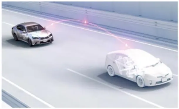
The navigation is related to identifying the location. Researchers use different techniques for navigation and positioning. An autonomous vehicle usually apply either Vehicle-to-Vehicle (V2V) communication [7,8], Dedicated Short-Range Communications (DSRC) [8] or Global Positioning System (GPS) with International Navigation System (INS) [7] . The GPS is the most popular one. However, it is unable to give reliable positioning accuracy in dense environments such as urban areas and indoor environments such as inside a garage or a house [9]. Most of the fully autonomous vehicles use V2V to recognize critical and dangerous situations at an early stage, and receive the required safety information in a short time. The autonomous vehicles communicate among themselves to exchange speed and direction data for every movement. Consequently, they can avoid crashing with each other. vehicles contineously recalculate and create a new digital map which gives the information on lane types, settings, and the most important thing which is the accurate location. Figure 1 shows how the safety-related information is instantly updated in V2V communication system. For example, V2V is used to improve spreading the alert message in urban environments which is called traffic density estimation system [10].
Figure 1: V2V Communication in autonomous cars [7]
2. Surrounding environment situation analysis system
Video cameras and visual image recognition techniques are used by most of the researchers to analyze environment surronding the moving objects. Other sensors can be combined with the visual sensors. Figure 2 shows how the surrounding environment situation can be analyzed using various types of sensors [7]. The analysis should be in real-time to ensure the system is always aware of the objects in the surrounding. Some systems depends on markers which is usually embedded in the infrastructure. Using object detection sensors gives more precise data to track all the moving objects and obstacles. Radar and ultrasonic sensors are widely used in this context. They use electromagnetic and ultrasonic waves.Radar and ultrasonic technologies are able to work reliably in difficult weather conditions such as fog or heavy rain. Laser rangefinder sensors called velodyne sensor also has been used to detects near objects then merge them in 3D-point cloud [11]. Another recent technique is using a remote sensing technology known as Light Detection and Ranging (LiDAR) [7]. LiDAR works with optical
detection using laser pulses instead of magnetic waves. It rapidly creates a 360° profiles and matches them to detect any movement or obstacle. An example of using the LiDAR is shown in Figure 3. A Simultaneous Localisation and Mapping (SLAM) technique is usually used along with LiDAR to correct the position that LiDAR detects [12]. It creates new shapes of each object which is recognized as new obstacle by LiDAR. Another used sensor is Microsoft Kinect, which is able to generate 3D information of the surroundings [13].
Figure 2: Surrounding environment situation analysis using various sensors [7]
Figure 3: Using LiDAR to scan the environment [7]
3. Motion planning system
A motion planning system monitors the vehicle‘s movements to determine a precise course of motion. This ensures that the moving vehicle remains in its lane and continues in correct direction as defined by the navigation system. Moreover, it guarantees that the vehicle can avoid collision with the static and moving objects which are identified by the environment analysis. Some of the sensors is unable to detects the moving objects so one of the used technique is SLAM and some artificial landmarks such as Wi-Fi, radio-frequency identification (RF IDs) and reflectors. It updates every movement of the near object [14]. The driving corridors algorithm is one of the popular motion planning algorithms. It uses the road boundaries and positions of the obstacles to find continuous coordinates [15]. There is another popular algorithmwhich reduces the distance between the vehicleand surrounding obstacles in generating the safe paths. The algorithm is known as Voronoi Diagram and it is shown in Figure 4 [16]. The red point detects the obstacle while the maximum distances from that obstacle is marked with grey lines and the path will be generated so that the vehicle can safely move forward.
Figure 4: Voronoi Diagram algorithms [16]
4. Trajectory control system
A trajectory control system is used to plan and decide the changes in speed and direction of the vehicle. It is also involved in observing and maintaining the driving stability by accelerating or adjustment of the steering for example. The trajectory control algorithms function by comparing the expected and actual changes after a speed or direction change [17]. Other than that, another approach has been introduced based on mixed-integer linear programming (MILP) [18]. This approach can handle tough obstacle and collision avoidance constraints automatically [19].
III.
SIGNIFICANT EXAMPLES OF AUTONOMOUS DRIVING APPLICATIONS
Autonomous technologies have been used productively in a number of different applications during the past few years [20]. The applications of autonomous driving can be divided into three types according to the three discussed above vehicle types:
1. Aerial vehicles
The aerial vehicles are usually applied in search and rescue, surveillance and scientific research missions and in dangerous environments and operations where the manned air vehicles are not suitable or not safe to be used [21]. The Unmanned Aerial Vehicle (UAVs) have many shapes and sizes, starting from micro UAVs through helicopters, up to giant strategic UAVs that can observe the targets for long periods of time [22]. One of the interesting research vehicle is Xcell-60 helicopter [23]. The model is tested based on two methods either flown by pilots or radio control (R/C) simulation. It is tuned using information provided by the R/C pilot during the test flights. Radio control means the helicopter is remotely controlled by an operator using the radio transmitter. Several actions, such as stall turns, loops, flips and split-S can be performed only by pilot. Then the same pilot flew these actions in the simulation environment. It includes high-resolution graphics displayed on a large screen, so that the pilot’s view of the helicopter is similar to the actual flight conditions. UAVs usually apply GPS in order to indicate position. Figure 5 shows a control block diagram for Autonomous Helicopter Supervisory as an example of theUAVs.
Figure 5: Control Block Diagram for Autonomous Helicopter Supervisory [23]
Recently, small-scale autonomous aerial vehicles, such as quadcopters, are starting to play a major role. The development of these micro-UAVs (MAVs) is becoming more popular because of their great agility and ability to perform fast actions [24]. Most of the MAVs are capable to operate without any human interaction, independent of the environment or mission and always makes intelligent decisions to achieve a specified goal. They also can create 2D and 3D maps of the environment they operate in. The aerial vehicles are improving along the time in terms of reaching higher altitudes and performing longer endurance as shown in Figure 6. Therefore, most of the UAVs use laser interferometry detection and ranging (LiDAR) and infrared cameras. Due to the high cost, some
researchers prefer to use Microsoft Kinect for the purpose of returning 3D information of the surroundings.
Figure 6: Global Observer UAS technologies were developed and tested across several platforms [25].
2. Underwater vehicles
Most of the underwater vehicles are torpedo-like with streamline bodies [26]. In 2002, an AUV was used at the Aquarius site. Figure 7 shows the Autonomous Underwater Vehicle known as Fetch which is used to collect scientific data. Another significant example is PIRO-Smart Underwater Robot (P-SURO) that has been invented in 2010 [27]. For the underwater vision, P-SURO uses one colour
camera that is placed at the nose as shown in Figure 8. Three range sonars are used for obstacle detection and assisting vehicle's underwater localization from forward, backward and downward. Three PC104 type PCM3353 SBCs (Single Board Computers) are implemented for vision, navigation, and control.
Figure 7: Fetch, an Autonomous Underwater Vehicle. Length 2 m. Weight 80 kg. [28]
Figure 8: P-Suro AUV [27]
3. Ground/surface vehicles
The military sector is an early adopter of surface self-driving vehicles [20]. One of the early examples is the military use of autonomous technologies for mine sweeping. This technology detects the mines and make sure it is safely deactivated or disabled [20]. This technology has saved countless lives of soldiers and civilians. In military sector, the autonomy is used to provide speed, reduce manual data processing and integration, and carry out actions within the capabilities of its software and hardware [29]. For the future, an effective team between airmen and autonomy need to be designed for two reasons. First, in the future autonomous system have the capabilities to act in a fully autonomous manner and deal with full range of missions. Second, there is always a need of command and control in certain missions for controlling autonomous system and coordinating with other forces in the mission space.
The main difficulty which prevents autonomous car technology to be available in market popularly, is the lack of the legislative laws. Lawmakers should find how to regulate these advancements. Nevada became the first U.S. state that provide license for driverless car in 2012[30]. It has been followed by California and Florida. Then, the Governor of California signed an Autonomous-Vehicles Bill into law. Senate Bill is the person in charged in creating the procedures and requirements for determining when autonomous cars are safe and ready to be use on the road. For
the first trial, a human must be in the car as a safety measure. Furthermore, the co-founder of Google, Sergey Brin that have developed self-driving cars, said he hopes that the cars will be on public streets in five years or less after California making them legal [31].
Autonomous cars usually use different types of sensors to operate. For example, the self-driving car in Figure 9 [32] uses two cameras to spot the lanes from left and right. Another camera is placed in the driver’s position in order to be able to spot the traffic lanes and traffic signs as if viewed by a normal driver. The Lidar is attached to the car to create a 3D model, including a real-time model of the environment. The 3D information, traffic lanes and the traffic signs are used by the supervisor software in order to calculate the collisions and the car’s path. The Artificial Intelligence calculation is provided by three different laptops. These laptops are synchronized using supervisor software called Master Software. The supervisor software component monitors all of the processed data by all other components and it is responsible in turning the steering wheels to maintain the car on the street/ road. It receives data from all other components via network and controls the car’s steering wheel using stepper motors.
Figure 9: Self-driving car diagram [32]
Figure 10 shows a conventional car (a Lexus RX 450h) modified by Google to become an autonomous car, without human driver. This car is capable of driving itself on both highways and urban streets. Lexus RX 450h use various sensors as shown in Figure 11.The list includes are GPS, LiDAR, Radar sensor, ultrasonic sensor and video cameras. The central computer will be the main center that control each of the sensor’s activities.
Figure 11: Inside the Lexus RX 450h [35]
Another early adoption of autonomous driving is by the aerospace industry. The National Aeronautics and Space Administration (NASA) has developed an autonomous extraterrestrial vehicle that apply an autonomous way-finding routine [7]. It evaluates the area ahead and decides independently which route is the safest. It must be not more than a few meters to take the pictures using detection cameras and hazard detection. It is called The Mars Rover Curiosity. The vehicle is shown in Figure 12. The vehicle takes several sets of stereo recording, then its on-board computer creates a map that identify all potentially dangerous obstacles. Later, it decides all possible ways to reach a predetermined target point and selects the safest routes to move.
Figure 12: The Mars Rover Curiosity [7]
IV.
TOWARDS AUTONOMOUS WHEELCHAIR
One of the purposes of this review paper is to discuss the best autonomous driving systems to be applied on our wheelchair project. The project aims to develop a conversion kit to convert a manual wheelchair to a smart electric wheelchair. Autonomous wheelchairs are studied by many researchers. Most of the studies focus on obstacle avoidance. Wheelchairs are not necessarily used on roads. Therefore, some of the researchers use GPS acquisition and processing to obtain the absolute position in an open space [12]. The GPS use Dynamic Measurement Unit (DMU) and International Navigation
System (INS) that consist of six to nine axis measurement. Landmark position refinement method have been used in [36]. The method identifies the shapes which is usually found in the surrounding environment such as trees, barriers, fences. But sometimes the reliability of this method can be decreased as the shape may not be standard. For example, the shape of a tree may differ or the fence may come at different angles. So, to improve this method, some artificial landmarks can be added such as reflectors, RF IDS, bar codes and Wi-Fi [12]. It can update and track its position over the time. Other than that, they also apply local positioning system acquisition and processing using LiDAR. It allows the distance to be mapped independently in the environment so it can be used either with or without GPS/INS system. LiDAR also can be used along with a camera to provide a powerful local positioning system that can be used to identify the landmarks and to map the local environment. The Simultaneous Localization and Mapping (SLAM) can also be applied to correct the vehicle positioning from the LiDAR distance and map.
One interesting early example of the obstacles avoidance systems uses 12 infrared sensors, 4 ultrasonic sensors, a front bumper and optical encoders [37]. The sensors arrangement is shown in Figure 15. Figure 16 represents all the physical devices that compose the system and shows the way they interact with each other. In the workstation platform a mouse and a joystick can be used to remotely control the wheelchair.
Figure 13: IR Sensor arrangement (top view) [37]
Figure 14: Physical devices that compose the system [37]
Another example is the Bremen Autonomous Wheelchair whichperceives its surroundings using 27 ultrasonic sensors [38, 39, 40]. It emphasis on obstacle avoidance, and can plan trajectories in advance of trajectory execution by using a local obstacle map [41]. The presence of an obstacle at the corresponding position in the environment is detected as shown in Figure 17.
Figure 15:The local obstacle map and a virtual sensor [39]
The virtual sensor comprises the cells the wheelchair will “visit” when driving with the steering angle indicated by the back wheels. The darker the cells, the nearer the wheelchair with the obstacles. Another autonomous wheelchair applies the LRF to detect the distances to objects in the surrounding [42]. The system comprise a tachometer which measures the wheel motor rpm to control the movement. The important step in developing an autonomous wheelchair is designing the space layout that the wheelchair need to move around. Therefore, the laser device is efficient for this application as it provides long range, high precision and high rate measurements.
In [43] authors created a personalized wheelchair navigation system by applying a personal digital assistant (PDA) equipped with wireless internet access and a GPS sensor. The GPS gives adaptive navigation support to the wheelchair users in any geographic environment. Nowadays, PDAs are replaced with smart phones which are usually equipped with many built in sensors that can be used to provide data for more advanced smart wheelchair’s activities [44].Users only need to touch the screen with less effort. Also they support designing easy-to-use graphical user interface (GUI) [45]. J. S. Nguyen used a stereoscopic camera and spherical vision system [46], 3D scanners like Microsoft’s Kinect and LRFs [47] which are shown in Figure 18, has become possible to use point cloud data to detect hazards like holes, stairs, or obstacles [26]. Figure 19 shows an example of obstacle detection using Microsoft’s Kinect sensor [48].
Figure 17:Determining navigability of terrain using point cloud data from a Microsoft Kinect [48]: (a) RGB image floor type 1 (F1) with an obstacle and a few bumps. (b) Point cloud map of F1 indicating obstacles with red, flat safe terrain in light blue, and bumps in shades of orange and yellow. (c) RGB image floor type 2 (F2)
with a doorpost and a terrain change from smooth to bumpy. (d) Point cloud map of F2.
Microsoft Xbox Kinect sensor provides RGB color and 3D depth imaging data. The main purpose of using Kinect device in this module is to provide 3D obstacles position from depth data which is necessary for obstacle detection algorithm and robot motion control. Figure 20 shows the control module for autonomous wheelchair using Kinect. It is a solution to the problem of wheelchair navigation in a 3D cluttered environment without human intervention.
Figure 18: Control module for autonomous driving wheelchair [50]
Some researchers have created systems that combining different type of sensors. For example, Drive Smart System (DSS) that apply Controller Area Network (CAN 2.0) for communication between nodes has been used for the wheelchair in Figure 21 [51]. The DSS can reduce the likelihood of sensor failure and limit the consequences of sensor failure.
Figure 19: Wheelchair that equipped with DSS [51]
The system is build up from 5 sensor nodes as shown in Figure 22. Each sensor node consists of up to five ultrasonic rangefinders (URs), five infrared rangefinders (IRs), two bumper inputs, two switch inputs, one beeper, and three status LEDs.
Figure 20: DSS block diagram [51]
V.
AUTONOMOUS VEHICLE LIMITATIONS
Although the autonomous driving system is one of the promising technologies to solve safety problems, but it still has some limitations to be widely commercialized. Most significant technical issue is safety. For example, after state of Arizona in United States has welcomed the autonomous driving systems, one of Uber's self-driving units was involved in a crash. Consequently, Uber Company halted the driverless tests temporarily. But, it was discovered later that the autonomous vehicle was not at fault [52]. However, it is a truth that autonomous system may not recognize or function well when there is water or snow on the path or road. It also cannot understand the hand signals from police officers at an accident. Autonomous vehicles sense the environment in different ways. Moreover, they make the decisions based on the inputs which are supposed to match with the algorithm that has been set up [53]. They do not have any empathy or sympathy. As long as they can reach the target, they will go for it. Human beings are different in that they can change their mind in a second based on their logical thinking and some uncontrolled expectations or due to extrasensory perception. Furthermore, sometimes there are unexpected bugs in software or unexpected failure in
sensors which may affect the whole system and lead to a misbehavior. Since, the system follows what have been set only, the unexpected situations, can affect people safety.
On the other hand, autonomous systems are high in price. In order to produce a good autonomous vehicle, many sensors are needed to cover multifunction roles: To identify the obstacles, determine how far the vehicle from obstacles is and lastly to avoid the obstacles itself. The more the accurate the sensors, the more the expenses are. However, evaluating costs depending on sensors and applications. Applications such as the mine sweeping technology that has saved countless lives are worthy even with the high costs. Sensors choice is dependent on applications as well. Optical remote LiDAR, GPS, camera, 3D Radar, Ultrasonic sensors and LRF are used in the above discussed systems. Each sensor has its advantages and disadvantages. LiDAR allows the distance to be mapped independently in the environment and it can be used either with or without GPS/INS system. It offers the higher accuracy compared to GPS. However, the LiDAR has high operating costs which is around 10k/ hour and degraded at high sun angles and reflections. GPS is the satellite based navigation system that determine the location based on the distance between receiver’s position and the GPS satellites. GPS also can be inaccurate due to bad atmospheric conditions, ephemeris errors, clock drift and bouncing of the GPS signal due to reflecting surface before reaching to receiver antenna. It is not a reliable service, as it is prone to lose accuracy and connection in urban canyons and indoor areas. While for ultrasonic sensors it consists of transmitter and receiver. It must view a surface to get adequate sound reverberation and may changes due to nature. The LRF provides long range, high precision and high rate measurements although it is a heavy device but cannot detect the near object such as in Figure 13. The main problems with laser scanner are high energy consumption and cost. One of the lowest cost sensors is sonar but the depth readings for this device are more coarsely spaced and less accurate. Common drawback for both laser and sonar, that they provide only readings for a horizontal plane parallel to the floor. The advantage of IR sensor, is that it does not have cross-talk and therefore it increases the speed of obstacle detection when compared with sonars. But on the other hand, it does not cover large area compared to sonars.
A 3D camera sensor, such as the Xbox Kinect been seen as an efficient device for the 3D navigation. It has structured light camera that can provide a set of dense depth measures via a fulcrum-base [51]. Furthermore, the cost of Kinect is relatively cheap, which makes it practical for robotic systems. The Kinect was found to be an effective tool for target tracking, localization, mapping and navigation [54, 55, 56]. By using the depth camera, the Kinect can acquire distance measurements and generate a depth image as shown n Figure 14.
Figure 22: Kinect working principle
VI. CONCLUSIONS AND FUTURE WORK
In this paper, a review of autonomous driving system has been made. The aim of this review is to investigate the latest studies in this field to figure out the most suitable techniques to apply on Electric powered wheelchair to allow users to move safely. From the review it is found that the most popular sensors that can be applied are Xbox Kinect, GPS, LiDAR and cameras. From the review study we suggest to implement our system using Microsoft Kinect and a GPS module. However, some improvement must be done. It is suggested to use RANSAC algorithm to remove plans captured by the Kinect. This method can detect important bodies that have a significant size in the entire cloud. For the GPS, it can be combined with the readings from tachometers, altimeters and gyroscopes to provide more accurate positioning. The ultrasonic sensors also can be used to measure the position of objects that are undetectable by Kinect.
Autonomous vehicles are theoretically safer. However, these systems are sometimes more dangerous than manned driving systems. Serious accidents sometimes result from sensing or computer system failures. Moreover, dangers can be in the form of a sudden, unexpected total failure of a computer system, which may result in an accident when occurring at a critical time. Tipping and falling is very common accidents for wheelchair users. Therefore, future work includes comprehensive testing on the safety aspects. For example, tipping can be caused by a variety of reasons which include making the wheelchair go to fast, unlocked brakes, slippery surfaces, the sitting stability of the user and hitting a large bump with one wheel causing the wheelchair to become unbalanced. As a suggestion, center of gravity evaluation is needed to stabilize the wheelchair movement in case the user is conducting activities such as bending, reaching and transferring in and out of the wheelchair. Auto braking system also can be considered.
REFERENCES
[1] Michael W. & Philip K. “A Philosophy for Developing Trust in Self-Driving Cars”.Preprint: G. Meyer & S. Beiker (eds.) Road Vehicle Automation 2 Lecturer Notes in Mobility, Springer, 2015, pp. 163-170.
[2] Hari B. “Wide-Area Internet Routing”, Massachusetts Institute of Technology Department of Electrical Engineering and Computer Science. 2009.
[3] Brian P. C. “Intelligent Transportation System (ITS) Evolution GPS/GNSS Role in Emerging Vehicle Fleets and Highway Infrastructure”. U.S. Department of Transportation (USDOT). 2014. [4] John M. “Improving Driving Safety Through Automation,” NHTSA. 2012.
[5] “Preparing for Autonomous Vehicles in Canada”. Canadian Automated Vehicles Centre of Excellence. 2015.
[6] Andrei E. F. “Real-Time Decision Making by Driverless City Vehicles a Discrete Event Driven Approach”. Griffith School of Engineering Institute of Integrated and Intelligent Systems Griffith University. 2010.
[8] Gary S. & Richard W. “Self-driving Cars: The Next Revolution”. Center for Automotive Research.
[9] Arghavan A., Reza M. V., Jesus M. & R. M. B. “Improving GPS-Based Vehicle Positioning for Intelligent Transportation Systems” Intelligent Vehicles Symposium (IV), IEEE. 2014.
[10] Julio A. S., Manuel F., Piedad G., Francisco J. M., Juan-Carlos C., Carlos T. C. & Pietro M. “An Infrastructureless Approach to Estimate Vehicular Density in Urban Environments”, Sensors 2013, 13, 2399–2406.
[11] Swarun K., Lixin S., Nabeel A., Stephanie G., Dina K. & Daniela R. “CarSpeak: A Content-Centric Network for Autonomous Driving”. Massachusetts Institute of Technology.
[12] William P. “Overview of Techniques and Applications for Autonomous Vehicles”. 2014.
[13] Hugo H. G. C. & Herman C. M. “A Primer on Autonomous Aerial Vehicle Design”. Department of Electrical, Electronic and Computer Engineering, University of Pretoria, Pretoria 0002. 2015. [14] Jesse L., Jake A., Jan B., Jennifer D., David H., Soeren K., J. Z. K., Dirk L., Oliver P., Vaughan
P., Michael S., Ganymed S., David S., Alex T., Moritz W. & Sebastian T. “Towards Fully Autonomous Driving: Systems and Algorithms”.
[15] Hardy, J. & Campbell, M. “Contingency planning over probabilistic obstacle predictions for autonomous road vehicles”. IEEE Trans. Rob. 29, 913–929. 2003.
[16] Takahashi, O. & Schilling, R.J. “Motion planning in a plane using generalized Voronoi Diagrams”. IEEE Trans. Robot. Autom. 5, 143–150. 1989.
[17] William B. D. & Richard M. M. Model predictive control of coordinated multi-vehicle formations. In Proc. 41st IEEE Conference on Decision and Control, pages 4631–4636, Las Vegas, NV, December 2002.
[18] Tom S. 2001. “Mixed integer programming for optimal collision-free path planning of autonomous vehicles”. Master’s thesis, Katholieke Universiteit Leuven, Department of Electrical Engineering, Leuven, Belgium.
[19] Dimitris B. & Robert W. Optimization over Integers. Dynamic Ideas, Bel-mont, MA, May 2005. [20] Mica R. E. “Autonomous Horizon: System Autonomous In The Air Force – A Path To The
Future”. Volume 1: Human –Autonomy Teaming. 2015.
[21] Lary, D.J., Objectively Optimized Earth Observing Systems, in Intelligent Aerial Vehicles, T.M. Lam, Editor. 2008.
[22] Natarajan, G. (2001) Ground control stations for unmanned air vehicles. Defence Science Journal, 51, 229-237.
[23] M. P. & Eric F. “Aggressive Maneuvering of Autonomous Aerial Vehicles: A Human-Centered Approach”.
[24] Mellinger D., Michael N. & Kumar V. “Trajectory generation and control for precise aggressive maneuvers with quadrotors”. Int. J. Robot. Res. 2012, 31, 664–674.
[25] Syed A. “Autonomous Unmanned Aerial Vehicles”. The George Washington University. 2012. [26] Sangekar, M., Chitre, M. and Koay, T. (2009). Hardware architecture for a modular autonomous
underwater vehicle STARFISH, OCEANS 2008, IEEE, pp. 1–8.
[27] Li Xuemin, Xu Yuru (2002). S-control of automatic underwater vehicles. The Ocean Engineering, 19(3), 81-84
[28] “Designing an Autonomous Underwater Vehicle (AUV): Concepts in Lift, Drag, Thrust, Energy, Power, Mass, and Buoyancy”. NOAA’s Aquarius America’s Innerspace Station.
[29] Andrew P.W. & Paul D. S. “Autonomous System: Issue for Defence Policymakers”. (Ed.). USA: Capability Engineering and Innovation Division.
[30] James M. “Self-Driving Cars”.
[31] Heather K. (2012 October 30). “Self-driving cars now legal in California” CNN. Retrieved from http://edition.cnn.com
[32] Using Artificial Intelligence to Create A Low Cost Self-Driving Car.
[33] Todd L. “Autonomous Vehicle Implementation Predictions”.Victoria Transport Policy Institute. 2017.
[34] Erico G. “How google’s self-driving car works,” October 2011. Retrieved 09/10/2017 from https://spectrum.ieee.org/automaton/robotics/artificial-intelligence/how-google-self-driving-car-works
[36] Chao G., Michael S. & John R. S. “Towards Autonomous Wheelchair System in Urban Environments”. 2009.
[37] Gabriel P., N. Honorio, C. Lopes, Urbano N., Anibel T. A. “Autonomous Wheelchair for Disabled People”.Proc. IEEE Int. Symposium on Industrial Electronics (ISIE97), Guimaraes, 797-801.
[38] Guillermo D. C. D. R. 2004. “Autonomous, Vision-Based, Pivoting Wheelchair with Obstacle Detection Capability”. Ph.D. Thesis. University of Notre Dame, Indiana.
[39] Axel L. & Thomas R. “A Versatile and Safe Mobility Assistant”. IEEE Robotics and Automation Magazine 7, No. 1. 29-37. 2001.
[40] Thomas R., Axel L., Rolf M. & Bernd K. “The Bremen Autonomous Wheelchair-A Versatile and Safe Mobility Assistant”. Bremen Institute of Safe Systems Center of Computing Technology University of Bremen.
[41] Thomas R. & Axel L. “Architecture and Applications of the Bremen Autonomous Wheelchair”. Proc Fourth Joint Conference on Information Systems, volume 1, Association for Intelligent Machinery, pages 365- 368. 1998.
[42] Jeppe M. H., Suren L. P. “Autonomous Wheelchair Navigation”.Section for Automation and Control Aalborg University, Denmark. 2008.
[43] D. Ding, B. Parmanto, H. A. Karimi, D. Roongpiboonsopit, G. Pramana, T. Conahan, and P. Kasemsuppakorn, “Design considerations for a personalized wheelchair navigation system”, In Proc. 29th Annu. Int. Conf. IEEE Eng. in Medicine and Biology Soc., pages 4790–4793, Lyon, France, Aug. 2007.
[44] Aleksandar M., Mladen M., & Emil J. “Smartphones for smart wheelchairs”, In IEEE Int. Conf. Body Sensor Netw., pages 1–6, Cambridge, MA, USA. 2013.
[45] Santhanam, V., & Viswanathan, V. (2013). Smartphone Accelerometer Controlled Automated Wheelchair.
[46] Jordan S. N. “A Smart Wheelchair System using a Combination of Stereoscopic and Spherical Vision Cameras”, PhD thesis, Univ. Technol., Sydney, 2012.
[47] Richard S. “Smart wheelchairs: A literature review”, J. Rehabil, “Research and Develop”, 42(4):423–436. 2005.
[48] Stephanie C., Gregory L., & Wyatt N. “Determining navigability of terrain using point cloud data”, In Proc. IEEE Int. Conf. Rehabil. Robot, pages 1–6, Seattle Washington, Jun. 2013. [49] Jesse L., and Hung M. L. “A Comprehensive Review of Smart Wheelchairs: Past, Present and
Future”. 2017.
[50] Emma B., Nader B. A., Mohamed J. “Autonomous wheelchair navigation with real time obstacle detection using 3D sensor”.761–773. 2016.
[51] Vinod K. S. “Design and Evaluation of a Distributed, Shared Control. Navigation Assistance System for Power Wheelchairs”. University of Pittsburgh. 2009.
[52] Mike I. (2017 March 25). “Uber Suspends Tests of Self-Driving Vehicle After Arizona Crash”, The New York Times. Retrieved from https://www.nytimes.com
[53] “Machines That Learn in The Wild”. Nesta. 2015.
[54] Patrick B. & Mo J. “Mobile robot navigation and target tracking system”, 6th Int. Conf. System of Syst. Eng., pages 299–304. 2011.
[55] William R. K. “Robotic person-following in cluttered environments”, Case Western Reserve University. EECS Dept. Master’s Thesis. 2012.
[56] Maurice F. F., Hordur J. & John J. L. “Efficient scene simulation for robust localization using an RGB-D camera”, IEEE International Conference on Robotic and Automation, pages 1663–1670. 2012.
![Figure 2: Surrounding environment situation analysis using various sensors [7]](https://thumb-us.123doks.com/thumbv2/123dok_us/263043.2526928/3.892.211.701.258.530/figure-surrounding-environment-situation-analysis-using-various-sensors.webp)
![Figure 4: Voronoi Diagram algorithms [16]](https://thumb-us.123doks.com/thumbv2/123dok_us/263043.2526928/4.892.284.598.103.425/figure-voronoi-diagram-algorithms.webp)
![Figure 6: Global Observer UAS technologies were developed and tested across several platforms [25]](https://thumb-us.123doks.com/thumbv2/123dok_us/263043.2526928/5.892.109.786.578.974/figure-global-observer-uas-technologies-developed-tested-platforms.webp)
![Figure 8: P-Suro AUV [27]](https://thumb-us.123doks.com/thumbv2/123dok_us/263043.2526928/6.892.211.661.459.731/figure-p-suro-auv.webp)
![Figure 9: Self-driving car diagram [32]](https://thumb-us.123doks.com/thumbv2/123dok_us/263043.2526928/7.892.198.707.379.733/figure-self-driving-car-diagram.webp)
![Figure 11: Inside the Lexus RX 450h [35]](https://thumb-us.123doks.com/thumbv2/123dok_us/263043.2526928/8.892.219.672.139.489/figure-inside-lexus-rx-h.webp)
![Figure 14: Physical devices that compose the system [37]](https://thumb-us.123doks.com/thumbv2/123dok_us/263043.2526928/9.892.263.631.753.1007/figure-physical-devices-compose.webp)
![Figure 15: The local obstacle map and a virtual sensor [39]](https://thumb-us.123doks.com/thumbv2/123dok_us/263043.2526928/10.892.308.589.106.516/figure-local-obstacle-map-virtual-sensor.webp)
![Figure 17: Determining navigability of terrain using point cloud data from a Microsoft Kinect [48]: (a) RGB image floor type 1 (F1) with an obstacle and a few bumps](https://thumb-us.123doks.com/thumbv2/123dok_us/263043.2526928/11.892.291.605.119.408/figure-determining-navigability-terrain-using-microsoft-kinect-obstacle.webp)
