An Automatic Test Case Generation Framework
for Web Services
Yongyan Zheng, Jiong Zhou, Paul Krause
Department of Computing, University of Surrey, Guildford, UK Email:{y.zheng,j.zhou,p.krause}@surrey.ac.uk
Abstract— BPEL (Business Process Execution Language) as a de-facto standard for web service orchestration has drawn particularly attention from researchers and indus-tries. BPEL is a semi-formal flow language with complex features such as concurrency and hierarchy. To test a model thoroughly, we need to cover different execution scenarios. As is well known, it is tedious, time-consuming, and error prone to design test cases manually, especially for complex modelling languages. Hence, it is desirable to apply existing model-based-testing techniques in the domain of web ser-vices. We proposed WSA (Web Service Automata) to be the operational semantics for BPEL. Based on WSA, we propose a model checking based test case generation framework for BPEL. The SPIN and NuSMV model checkers are used as the test generation engine, and the conventional structural test coverage criteria are encoded into LTL and CTL temporal logic. State coverage and transition coverage are used for BPEL control flow testing, and all-du-path coverage is used for BPEL data flow testing. Two levels of test cases can be generated to test whether the implementation of web services conforms to the BPEL behaviour and WSDL interface models. The generated test cases are executed on the JUnit test execution engine.
Index Terms— web services, finite state machine, model checking, test coverage, test case generation
I. INTRODUCTION
Web services is an emerging paradigm which pro-vides a flexible, re-usable, and loosely coupled model for distributed computing. BPEL is the de-facto indus-try standard language to model the behaviour of web service compositions. BPEL is a semi-formal flow-based language with complex features, which may thus include fault behaviours. It becomes essential to verify a web service design before publishing it, and to test whether the published service conforms to the design model. However, the manual writing and verification of test cases for complex models is tedious, time-consuming and error prone. Hence, it is vital to automate this process.
A number of proposals have been made that use model checking for the rigorous verification of BPEL [1]. We identify two problems of the existing approaches. First, BPEL activity relationships can be categorised
This paper is based on “A Model Checking based Test Case Genera-tion Framework for Web Services,” by Y. Zheng, J. Zhou, and P. Krause, which appeared in the Proceedings of the International Conference on Information Technology (ITNG), Las Vegas, Nevada, USA, April 2007.
c
2007 IEEE.
This work was supported by the EU FP6 funded project Digital Business Ecosystem.
into control-flow and data-flow. Since BPEL is a semi-formal flow language, various semi-formal semantics have been proposed, so that BPEL models can be verified rigorously. However, most current formal models only focus on modelling BPEL control flow, and do not cover the BPEL data flow analysis. Second, there exist two kinds of interactions of BPEL: internal and external. The external interactions between BPEL models are by message pass-ing. The internal interactions between activities of a BPEL model, are modelled explicitly by control dependencies and implicitly by data sharing. Those internal interactions caused by data sharing will be omitted if an approach does not cover the BPEL data flow analysis. Furthermore, there is less material in the literature on automatic test case generation from BPEL models. From the model-driven-testing point of view, existing model checking tools can be reused for the purpose of verification and testing of BPEL. With model checking, a BPEL model can not only be a design model for verification, but also be a test model for deriving test cases.
The formal semantics proposed to date for BPEL can be categorised as process algebra based, Petri-net based, and automata based. Since the verification tools for process algebras are less mature, and using Petri-nets as the formal models for BPEL has scalability problems, we choose an automata-based approach, so that a rich range of mature model checking tools can be applied. Our formal model is designed to be used by the verification tools. We propose a Web Service Automaton (WSA), an extension of Mealy machines, which covers data, supports message passing communication, and adapts the asynchronous interleaving semantics. In this paper, we justify the suitability of WSA for BPEL on two counts: (1) our model supports separate analyses of BPEL control and data flows; (2) its message passing communication provides a uniform semantics for both BPEL internal and external interactions. Based on WSA, we provide a model checking based test case gen-eration framework for BPEL. We support the application of both SPIN and NuSMV model checkers as the test gen-eration engines, and we encode the conventional structural test coverage criteria into LTL and CTL temporal logic. State coverage and transition coverage are used for BPEL control flow testing, and all-du-path coverage is used for BPEL data flow testing. Test cases can be generated to test whether the implementation of web services conforms to the BPEL behaviour and WSDL interface models. To our knowledge, none of the prior research studies
the verification and test case generation of both BPEL control-flows and data-flows in a unified approach. In summary, our main contributions lie in the two aspects: (1) proposing a web service automaton (WSA) as the operational semantics for BPEL, which is suitable for model checking; (2) analysing BPEL control and data dependencies in WSA; (3) presenting an automatic test framework for BPEL web services.
The rest of the paper is organized as follows. Section II introduces the background of BPEL language, the semantics of our WSA, and the modelling of BPEL in WSA. Section III presents our test framework in details. Section IV provides a case study and tool support to demonstrate our approach. Section V reviews the relevant literature. Finally, section VI concludes the paper and outlines future work.
II. BACKGROUND
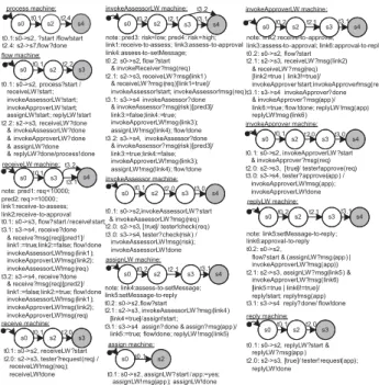
In this section, we briefly describe BPEL features, present our web service automata (WSA) together with how to capture BPEL control and data dependencies in WSA, and model checking in testing. In the following sections, we usemachine as shorthand for a web service automaton, and call the machine associated with BPEL x activity as x machine. In state machine diagrams, an initial state is pointed by an arrow started with a filled black circle, and a final state is shaded.
A. BPEL Language
BPEL is a flow-based language in XML format. BPEL consists of two categories of activities: basic and struc-tured activities. Basic activities are atomic actions, includ-ingreceive, reply, assign, invoke, throw, terminate, empty, andwait. As with programming languages, the structured activities impose control flow dependency constrains on the executions of either the basic or structured activities within them. A structured activity can contain an arbitrary depth of sub-activities. The structured activities include pick, switch, while, sequence, flow, scope, eventHandlers, faultHandlers, compensationHandler. For data handling, BPEL uses the blackboard approach, where a set of variables is shared by all activities within the same scope. Since every web service shall have its own business logic, a web service should be associated with a be-havioral model in addition to the web service interface description. As a well known orchestration language for the interactions of multiple web services, BPEL is rich enough to also describe the behaviours of single services. So, we suppose that a web service is associated with two models: a BPEL process as the behavioural model, and a WSDL description as the interface. From the testing point of view, when more than one BPEL process is considered, the system boundary needs to be included. The process within the system boundary are called SUT (service under test), and a process outside the system boundary is tester. We use the loan approval service from the BPEL standard [2] as the discussion example.
The loan approval service includes four web services: customer, approval, assessor, and approver. The approval service acts as the orchestration service to interact with other services. The BPEL standard provides an approval BPEL process for the loan approval example.
receive assign reply req<10000 req >=10000 info info risk=”low” risk=”high” approval req info req info req risk reply req<2000 req>=2000 risk=”high” assign1 assign2 risk=”low” assessor invoke Approver invoke Assessor reply req<5000 req>=5000 info=”no” assign1 assign2 info=”yes” approver receive receive customer service assessor service customer service approver service assessor service assessor service req risk approver service req approver service info (1) (2) (3)
Figure 1. The loan approval business scenarios
The business requirement of the approval service is illustrated in part (1) of Fig 1. The approval service starts by receiving a request from the customer. If the request is less than10000, it forwards the requests to the assessor service; otherwise it forwards the request to the approver service. The assessor evaluates the request and returns a risk result. The approver evaluates the request and returns an approved result. When the returned risk from the assessor is low then the approval service replies the customer by a granted loan; otherwise if the returned risk from the assessor is high, the approval service calls the approver. After getting response from the approver, the approval service replies the customer of the loan decision. In addition to the approval service, the assessor and approver services must have some business logics to decide whether an incoming request has high risk or low risk, and whether a high risk request can be granted. We add BPEL processes for the assessor and approver services. Their business requirements are shown in parts (2) and (3) of Fig 1.
B. Web Service Automata
The static semantics of a web service automaton ex-tends a finite state machine with signature, data structure, and message storage schema. Asynchronous execution of web services is achieved by using queues for message processing. The default queuing protocol in WSA is to associated an FIFO queue for each message. We assume that each WSA is equipped with a finite multi-setbuffer to store the incoming messages. WSA communicate by message passing.
Definition 1: A Web Service Automaton (WSA) M
is a sextuple M = (IM, SM, s0M, Sf M, TM, δM). As a
convention, we omit the subscript of M so that M = (I, S, s0, Sf, T, δ).
1) I is the signature of M, denoted as a triple I = (E, L, O), whereE, L, Oare pair-wise disjoint and represent sets of input, internal, and output events, respectively. LetM sg= (L∪E∪O)be the set of events, we assume thatL is the disjoint union of a set Lin of internal input events and a set Lout of
internal output events, and the elements of(E∪O) will be called external events.
2) S is a set of states,s0∈Sis the initial state,Sf ⊆S
is a set of final states.
3) T ⊆(EX∪{Ω})×BX×(℘(AX∪O∪Lout)∪{Ω})
is a set of transitions, where:
• EX is the set of Boolean expressions over
input event sets E ∪Lin, linked by logical
operators AND, OR, and NOT, denoted as ∧,∨, and¬respectively. LetV be a countable infinite set of variables ofM.AX is the set of assignments overV.BX is the set of Boolean expressions overV.
• For each transition t= (ex, g, a)∈T (graph-ically denoted as ex[g]/a), ex ∈ EX ∪ {Ω} is the input event expression, g ∈ BX is the guard predicate, anda⊆℘(AX∪O∪Lout)∪
{Ω}is the action set composed of assignments and output events. Ωindicates the omission of an input event expression or an output event. The components of transitiont are denoted as
t.ex=ex, t.g=g, t.a=a.
• If there exist two statementsst1, st2∈t.a∩AX
where def(st1) = def(st2), then st1 ≡ st2
(see the definition ofdef below).
4) δ⊆S×T×Sis the transition relation (graphically denoted as s→t s0). If s→t s0 witht = (ex, g, a), then if the machine is in state s, the t.ex and t.g
are evaluated to true, then the machine executes the set of instructionsaand change state tos0.
We use symbols ?,!,@ as a convention in diagrams to indicate whether an event is input, output, or internal event, denoted as?e∈E,!e∈O,@e∈L, respectively.
Let st denotes a statement that represents an input event of machineM, output event of M, assignment, or Boolean expression. First, we define three functions:
• def : (AX∪EM)→℘(V), wheredef(st)⊆℘(V)
returns the assigned variables of a statement, i.e. the variable on the left hand side of an assignment, and the input event parameters ofM.
• cuses: (AX∪OM)→℘(V), wherecuses(st)⊆V
returns the variables on the right hand side of an assignment, and the output event parameters of M.
• puses : BX → ℘(V), where puses(st) ⊆ V
returns the variables in the Boolean expression over variables.
Definition 2: The data structure of machine M
is a triple (VM, AXM ∪ EM ∪ OM, BXM), where
AXM, BXM can be retrieved from the transition set
TM. AXM = {st ∈ AX|∃t ∈ T.st ∈ t.a} and
BXM = {st ∈ BX|∃t ∈ T.st ∈ t.g}. VM is the
union of S
st∈(AXM∪EM∪OM)(def(st)∪cuses(st))and
S
st∈BXMpuses(st).
C. Modelling BPEL Control Dependencies
Since a WSA has no hierarchy, we simulate the hi-erarchical control dependencies of BPEL activities by the parent and child relationships between machines. A
machineMA is a parent of machine MB ifMA sends a
start message toMB. A child machine can optionally send
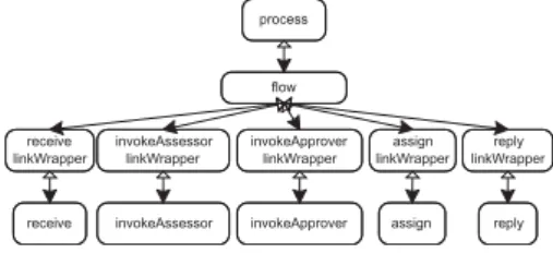
a done message to its parent machine when reaching one of its final states. Each machine has0..1parent machines, and0..∗child machines. Since the BPEL basic activity is atomic and a BPEL structured activity is hierarchical, the machine for a BPEL basic activity has no child, and the machine for a BPEL structured activity has 0..∗children. Fig 2 shows the machine relationships of the approval BPEL process. The dark arrows denote thestartmessages sent from parents to children.
process invokeApprover linkWrapper flow receive linkWrapper invokeAssessor linkWrapper reply linkWrapper assign linkWrapper
receive invokeAssessor invokeApprover assign reply
Figure 2. An example of machine hierarchy
Common Machine Layout. With consideration of fault and interruption, the machines for BPEL structured activities have a common layout, shown in Fig 3. A machine can have one or more child machines. Each machine has a stopStatus as a local variable. Suppose
M is a machine, we can derive three scenarios from this common layout: 1) when M receives a fault from its children and no stop message arrives, it forwards the fault to its parent (ti.3), and the 2) scenario is followed;
2) whenM is interrupted by receiving a stop message, it propagates the message to its children (ti.0) and updates
the stopStatus to true. Upon receiving the child machines’ done messages, if the current stopStatus is true, then the machine enters an abnormal final state(ti.1); 3) whenM
receives the children’s done messages and no fault or stop message arrives, it ends normally (ti.2).
WSA transitions:
ti.0: si->si, parent?stop(tm)/stopStatus:=true;child1!stop(tm);..;childn!stop(tm) ti.1: si->s1,child1?done..&..childn?done [stopStatus=true]/parent!done ti.2: si->si+1, child1?done..&..childn?done
&¬(child1?fault(f)..|..childn?fault(f) | parent?stop(tm))/parent!done ti.3: si->si, (child1?fault(f)..|..childn?fault(f)) & ¬ parent?stop /parent!fault(f) si si+1 ti.2 ti.3 s1 ti.0 ti.1
Figure 3. The common machine layout
It can be observed that the priority of the incoming events from high to low is: stop, fault, and done mes-sages. In transition ti.2, we do not use the predicate
stopStatus! = true to guard the transition. In the
case that both done and stop messages have arrived, the stopStatus is updated to true only when the stop message is consumed, so the predicte stopStatus! = true has no impact on the selection of consuming done or stop message. Without using the priority constraints on events, the machine only consumes one of them randomly. So, we introduce multiple-input events to the transition.
In the following, we show that a machine’s input events with logical AND, OR, NOT can capture various BPEL features.
si sj parent?start/ child1!start;..;childn!start
... sk sl
child1!done & child2?done ..&..childn!done/parent!done
si child1!fault1 | child2?fault2 ..|..childn!faultn/parent!faulti si
ti.2: ?e & ¬child?fault & ¬parent?stop ti.1: child?fault & ¬parent?stop ti.0: parent?stop (1)
(2) (3)
Figure 4. Multiple-input events
Concurrency. BPEL flow, scope, and eventHandler activities allow the enclosed activities to perform concur-rently. We use flow activity as an illustration here. When the flow enters, all the enclosed activities start. The flow ends when all the enclosed activities end. We model this by two transitions, shown in (1) Fig 4. On the left of (1), the flow machine starts all its children as a transition action, so that all child machines will start at the same time. On the right of (1), a logical-AND operator is added to the transition input events, so that the flow machine will not end until all its children end by sending done messages.
Fault Propagation. When a structured machine re-ceives a fault message from its children, it forwards the fault message to its parent. Suppose the structured activity encloses more than one activity. The fault is propagated as long as one of the enclosed activities raises a fault. We model this by adding a logical-OR operator to the transition input events, shown in (2) of Fig 4. Instead of using a queue for each fault, we use one FIFO queue to store all fault messages, so the fault message sent from the activity machine to its parent depends on which child’s fault comes first.
Interruption. BPEL has two kinds of Interruptions. First, when a termination message is thrown when a terminate activity is reached, the process machine ends abnormally, and a stop message is propagated downstream from the process machine. Second, when a fault is thrown by a throwactivity or aninvokeactivity, the fault will be propagated upstream until it can be caught by a scope or process activity that has the faultHandlers to handle this fault. The scope or process activity will stop its normal activities before enabling the faultHandlers. The stop message is propagated downstream from the scope or process machine. When a structured activity is stopped, all its children need to be stopped first. This is modelled by propagating a stop message downstream. The priority of a stop message is captured by adding logical-AND together with logical-NOT to transition input events. A stop message has higher priority than a fault message, which in turn has higher priority than a normal message. In (3) of Fig 4, transition ti.0 is triggered when a stop
message arrives. The transitionti.1will be triggered when
it receives a fault message from its child, and only when no stop message arrives. It indicates that a fault will not be propagated when the machine is asked to stop. The transitionti.2indicates that a fault or interruption message
has higher priority than a normal incoming message.
Synchronisation of Activities and
Dead-Path-Elimination. A set of links can be declared in the flow construct to express the synchronisation dependencies between activities within a flow. A link is a Boolean variable, and each link is associated with a pair of source activity and target activity. For instance, if MA andMB
are source and target activities of a link l1, respectively,
thenl1 isMA’s outgoing link withsourcetag, andMB’s
incoming link withtarget tag.
The synchronisation between source and target activi-ties is realised by setting and getting the link value. The source activity sets the link to be true or false, and the target activity gets the link value. The target activity can start when 1) all the incoming links’ values are defined by the source activities, and 2) its associatedjoin-conditionis satisfied, which is a user-defined logical constraint on link values. The default logical constraint is OR. If the join-condition is false, the target activity will not be executed and this effect will be propagated downstream in the flow model. This is called Dead-Path-Elimination in BPEL. We capture the dead-path-elimination feature by updating the related links to false, and sending the link-related data exchange messages to the target activity machines.
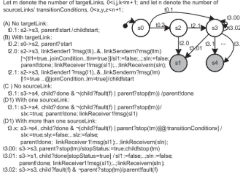
The target tag and source tag are standard elements of BPEL constructs, indicating every BPEL activity may or may not have incoming links and outgoing links. It would be too complicate to consider handling for each activity, so we use a supporting linkWrapper machine to handle links. When an activity has incoming or outgo-ing links, it will associate with a linkWrapper machine and a core machine. The linkWrapper will be the core machine’s parent. When an activity has no link, it is only associated with a core machine. This separation simplifies the structure of a machine, and allows BPEL activities to share a common machine structure for link handling. Fig 5 shows the linkWrapper machine structures, which covers the cases when an activity 1) has source links but no target link, 2) has target links but no source link, 3) has target links and source links.
s0 s4 s3 s1 t2.1 t2.0 t3.1 t3.n Let m denote the number of targetLinks, 0<i,j,k<m+1; and let n denote the number of sourceLinks’ transitionConditions, 0<x,y,z<n+1;
(A) No targetLink: t0.1: s2->s3, parent!start /child!start; (B) With targetLink: t0.2: s0->s2, parent?start t2.0: s2->s3, linkSender1?msg(tli)..&..linkSenderm?msg(tlm) [¬(tl1=true..joinCondition..tlm=true)]/sl1:=false;..;sln:=false; parent!done; linkReceiver1!msg(sl1);..;linkReceivern(sln); t2.1: s2->s3, linkSender1?msg(l1)..&..linkSenderm?msg(lm) [l1=true [email protected]=true]/child!start (C ) No sourceLink:
t3.1: s3->s4, child?done & ¬(child?fault(f) | parent?stop(tm)) /parent!done (D1) With one sourceLink:
t3.1: s3->s4, child?done & ¬(child?fault(f) | parent?stop(tm))/ slx:=true; parent!done; linkReceiver1!msg(sl1) (D1) With more than one sourceLink:
t3.x: s3->s4, child?done & ¬(child?fault(f) | parent?stop(tm))[@transitionConditionx] / slx:=true;sly:=false;..slz:=false;
parent!done; linkReceiver1!msg(sl1);..;linkReceivern(sln); t3.00: s3->s3, parent?stop(tm)/stopStatus:=true;child!stop(tm) t3.01: s3->s1, child?done[stopStatus=true] / sl1:=false;..;sln:=false;
parent!done; linkReceiver1!msg(sl1);..;linkReceivern(sln); t3.02: s3->s3, child?fault(f) & ¬parent?stop(tm)/parent!fault(f)
t3.00 t3.01 t3.02 ... s2 t0.1 t0.2
Figure 5. linkWrapper machine
Suppose MB is the core machine and MA is the
linkWrapper machine for an activity, several scenarios can be derived from the machine structure. For case 1), when an activity has source links but no target link, two normal scenarios follow the paths ht0.1, t3.1i,ht0.1, t3.1, .., t3.ni.
The machineMAstarts by receiving a start message from
MB has finished,MA send a done message to its parent.
If the activity has one source link l1,MAsets the linkl1
to true and sends the link exchange messagemsg(sl1)to
the machine of the link’s target activity. If the activity has more than one source linksl1, ..sln, for the
transitionCon-dition of linkslxis evaluated to true, only one linkslxis
set to true and the rest links are set to false. Thereafter,
MAsends the link messagesmsg(sl1);..;msg(sln)to the
machines of the links’ target activities. For case 2), when an activity has target links but no source link, a normal scenario follows the path ht0.2, t2.1, t3.1i. MA receives
link messages msg(tl1), ..msg(tlm) from the machines
of the links’ source activities. MA waits for all the link
messages to arrive and check whether the links satisfy the joinCondition. For case 3), when an activity has target links and source links, machine MA handles the target
links in the same way as the case 2), and the machine handles the source links the same as the case 1).
When all the link messages have arrived and the links do not satisfy the joinCondition, ajoinFailureoccurs and
MA ends abnormally by updating all the source links
to false and sending the link messages to the machines of links’ target activities (t2.0). Alternatively, when MA
receives a fault fromMB(t3.02),MApropagates the fault
to its parent. As long as MA receives a stop message
from its parent (t3.00),MA propagates the stop toMB.
After having received MB’s done message, MA ends
abnormally by setting all source links to false and sending the link messagesmsg(sl1);..;msg(sln)to the machines
of the links’ target activities (t3.01).
D. Modelling BPEL Data Dependencies
Data flow captures the relations between inputs and outputs of BPEL activities. In BPEL, variables and flow-links may affect the control flow; variables may appear in the condition expressions of switch and while activities, and may also be used in the conditions to fire particular flow-links in the source element. So taking into account variables is essential in the formal model. There are two types of variables in BPEL: BPEL variables and links. BPEL variables are declared in the variables tag of either process or scope activity. The flow-links are Boolean vari-ables declared in the links tag of theflowactivity. BPEL handles data by a blackboard approach. BPEL variables and flow-links can be used and defined by the process or scope enclosed activities, and the flow enclosed activities, respectively. We analyse BPEL activities to discover data dependencies among activities. In the following, for a message msg(x) ∈ EM ∪OM, msg and x denote the
message name and input/output parameter, respectively. Let{Mm..Mn}be the set of machines selected as SUT,
a messagemsg(v)sent from machineM1to machineM2,
and a transition tassociated with variable x, we have:
• t is annotated withdf(x)if a)xis defined in an as-signment action oft, i.e.{x∈def(exp)|exp∈t.a}; or b) x = v is the input parameter of M2
whereM1 andM2 are tester and SUT respectively,
i.e. {x∈def(exp)|t∈TM2∧exp∈t.ex}, M2 ∈
{Mm..Mn},M1∈ {/ Mm..Mn}.
• t is annotated with us(x) if a) x is used in an assignment action or guard
of t, i.e.{x∈cuses(exp)|exp∈t.a} or
{x∈puses(exp)|exp∈t.g}; or b) x = v
is the output parameter of M1 where M1
and M2 are tester and SUT respectively, i.e.
{x∈cuses(exp)|t∈TM1∧exp∈t.a∩OM1},
M2∈ {Mm..Mn},M1∈ {/ Mm..Mn}.
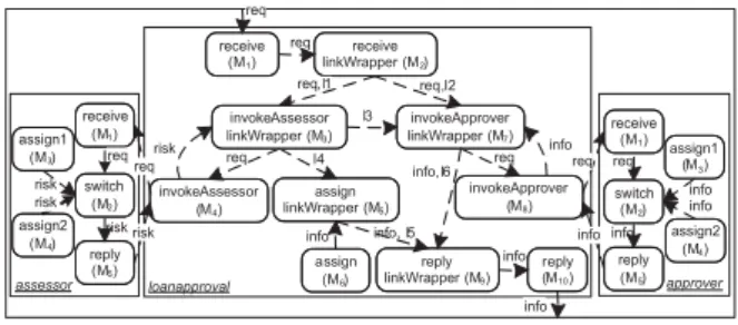
The BPEL data dependencies are captured by three data exchange models: (1) An internal-data-exchange model is used for a single BPEL process to specify the relation between inputs and outputs of BPEL activities. An external-data-exchange modelis used to capture how messages are transferred from one BPEL process to other BPEL processes. When a single BPEL process is selected as SUT, an internal-data-exchange model is enough to capture the BPEL data semantics. When multiple BPEL processes are selected as SUT, a global-data-exchange modelwhich is the union of the internal and external data exchange models is required to capture the BPEL data semantics. The internal-data-exchange model is captured by deriving a set of machine sequences for each BPEL variables and flow-links. The external data exchange model can be easily constructed from BPEL activities by identifying which partnerLink a message is sent to or received from. The detailed analysis of BPEL data dependencies can be found in [3]. Fig 6 shows the global-data-exchange model of the loan approval example.
invokeApprover linkWrapper (M7) receive linkWrapper (M2) reply linkWrapper (M9) assign linkWrapper (M5) invokeAssessor (M4) invokeApprover (M8) assign (M6) reply (M10) req req req,l2 req,l1 req risk req l4 req receive (M1) l3 info risk info invokeAssessor linkWrapper (M3) info, l5 info info,l6 info loanapproval receive (M1) switch (M2) assign2 (M4) reply (M5) assessor assign1 (M3) assign2 (M4) reply (M5) approver info req req risk risk risk assign1 (M3) req info info info receive (M1) switch (M2)
Figure 6. Global data exchange model
E. Model Checking in Testing
The idea behind model checking is to check whether a given model satisfies a given property, by exploring all possible alternatives of the given model. There are two inputs to a model checker: the model, based on a finite state machine; and, the property, expressed as a temporal logical formula. When the given property is not satisfied, the model checker outputs a set of counterexamples. A counterexample is an execution path that will take the finite state model from its initial state to a state where the violation occurs.
The SPIN model checker supports LTL temporal logic, and the NuSMV model checker supports both LTL and CTL temporal logic. LTL (Linear Time Temporal Logic) views time as a sequence of states with no choice as
to which state is next. The choice of next state is de-terministic. CTL (Computation Tree Logic) views time as branching, so from a given branch alternative states may be reached. In our framework, we will use the LTL temporal operators [] (always), (eventually), X (next), andU (until); and the CTL temporal operatorsA(for all paths),E(there exists some path),G(always),F(finally),
X (next), andU (until).
The attraction of applying model checking in testing is that model checking can automatically produce counterex-amples, which can be the basis for test cases. Proposals for applying model checking in coverage-based testing were made by [4], [5], [6]. The idea is to use a model checker to find test cases by formulating test purposes as trap properties. An example of a test purpose is ’a state is reachable’. Atrap propertyis the negation of the original desired property, such that counterexamples can be generated for a non-error test model. The test case generation process is summarised as three steps: 1) a given test purpose is encoded into a trap property; 2) the model checker checks the given model against the trap property, and generates counterexamples; 3) test cases can be retrieved from the counterexamples. Test coverage can be achieved, by repeating such process for each test purpose for the given model. For instance, suppose the test criterion is state coverage for a machine M with states
s1, s2, s3, s4, this requires four test purposes where each
corresponds to ’state si is reachable’. By encoding the
test purposes into trap properties, the model checker will search for counterexamples for each test purpose.
III. TESTCASEGENERATIONFRAMEWORK
In this section, we will elaborate our proposed test framework for BPEL test case generation. First, we will introduce how to simplify WSA for the purpose of im-proving the performance of model checking. Second, we will briefly describe the mapping from WSA to Promela and from WSA to SMV. Afterwards, we will present how to apply model checking in test case generation.
A. Overview
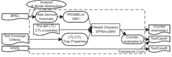
Fig 7 gives an overview of the test framework. The user selects one or more verified BPEL models as the SUT, picks a pre-defined test coverage criterion, and chooses a model checker. Inside the framework, the selected test coverage criterion is encoded into a set of trap properties. The BPEL processes are analysed and transformed into our proposed WSA, which in turn are transformed into Promela or SMV models (Promela and SMV are the input languages of the SPIN and NuSMV model checkers, respectively). In order to tackle the state space explosion problem of model checking and to speed up the checking performance, some model simplification techniques will be introduced for WSA. After the model transformations, the model is model-checked against the trap properties (see section III-D). A set of counterexamples will be generated. The transition IDs can be retrieved from the
counterexamples. By the transition IDs, we can get the inputs, guards, and outputs of the corresponding transi-tions from WSA. Also, the message types of the inputs and outputs can be extracted from the WSDL interface. As a consequence, the test framework will produce BPEL based test cases that enable the user to input test data. After executing the test cases, the user can verify whether the responses from the BPEL model are operating as expected. The test cases can check whether the composed web service conforms to functional requirements.
Model Checkers SPIN/nuSMV PROMELA/ SMV LTL/CTL Trap Properties Web Service Automata Counter-examples-II Test Coverage Criteria BPEL WSDL TestCaseA TestCaseB Pre-def LTL/ CTL properties Analysis & Model abstraction
Counter examples-I
Framework Core
Figure 7. Framework architecture
B. Model Simplification in WSA
The abstraction is important for formal analysis with model checking techniques. In WSA, the complex data type and the concrete data value of BPEL variables will be abstracted; also the BPEL predicates will be abstracted. The abstraction will not hinder the model checking but will help to speed up the model checking. To further simplify the model, those redundant transitions and states related to faults and interruptions will be removed. The model reduction can alleviate the state explosion problem inherent of model checking techniques.
Abstraction of BPEL Predicates. We introduce a symbolic predicate for those decision points where the no concrete value of message is available by the time of analysis. From the point of view of model verification and testing, such a decision point could be considered a symbolic predicate which may equally be true or false. For example, in the approvalBPEL process, the receive activity has two guarded outgoing links, where the guards
are request.amount < 10000 and request.amount ≥
10000. Here request is a BPEL variable, which is as-signed a value by a message from an external service. Since the actual value of request is not determined by the time of static analysis, we use symbolic predicates
pred1, pred2 to abstract the actual guards. Since the
values of symbolic predicates would be either true or false will equal probability, the values of pred1, pred2 can be
(1,0),(0,1),(1,1),(0,0)where1,0denote true and false respectively. However,pred1, pred2are not allowed to be
true or false simultaneously, since the guards of outgoing flow-links of an activity should be mutually exclusive. Therefore, some logical constraints need to be added to the symbolic predicates. In the example, the logical constraint is pred16=pred2.
In BPEL, a symbolic predicate will be introduced at the control decision points where the condition expressions are explicitly modelled. The symbolic predicates and logical constraints can be introduced in the following:
(1) For the transitionConditions of sourceLinks in an activity, a symbolic predicate is introduced for each transitionCondition. These predicates should be mutually exclusive. Suppose p1, p2, p3 are the predicates, the logical constraint should be (p1∧ ¬(p2∨p3))∨(p2∧ ¬(p1∨p3))∨(p3∧ ¬(p1∨p2)). (2) For the condition of a while activity, two mutual exclusive symbolic predicates are introduced. Let
p1, p2 be the predicates. The logical constraint should be(p1∧ ¬p2)∨(p2∧ ¬p1).
(3) For the condition expressions in the case and oth-erwise constructs of a switch activity, a symbolic predicate is introduced for each of them. Let pi
denote a condition expression, where1≤pi≤n−1 and pi = n are the condition expressions of case
and otherwise, respectively. The logical constraint should be(¬p1∧p2)∨(¬(p1∨p2)∧p3)∨(¬(p1∨
p2∨p3)∧p4)..∨..¬(pn−3∨pn−2∨pn).
In order to derive the logical constraints precisely for all predicates in a BPEL process, a specific tool is required.
Abstraction of BPEL Variable Types and Values.
A BPEL variable can be declared as one of the three types: WSDL message type, XML Schema element, and XML Schema type. A WSDL message type and a XML element must be a complex type, while a XML Schema type can be either a simple or complex type. A complex type is a type with enclosed elements. If the variable is a WSDL message type, we need to search the WSDL model for the declaration of such a message type, so that such a variable can be declared as a complex type in Promela or SMV. In SMV modules, for a variable with a complex type in an assignment expression or in a message sending, all the enclosed elements need to be parsed and handled one by one. Since such additional modelling heavily complicates the Promela and SMV models and slows down the model checking, we abstract the complex types into abstract types without enclosed elements. An abstract type corresponds to the BPEL variable’s type name itself. For instance, if a BPEL variable is declared as a WSDL message typecreditInformationMessage, the corresponding abstract type is simply named creditInfor-mationMessage. So the WSDL model does not need to include data type definitions in the mappings from BPEL-to-WSA, WSA-to-PROMELA, or WSA-to-SMV.
Because the data type is abstracted, the data value also needs to be abstracted. For instance, a BPEL variable request has WSDL message type creditInformationMes-sage, which includes an amount part. There may exist request.amountin the model, we abstract it into the BPEL variable itself request. In the case that a BPEL variable is assigned a value, we abstract the actual data value into defined. This abstraction will influence the predicate evaluation. However, with the above symbolic predicates, the abstraction of data values has no side-effect on the model checking.
Removal of Fault and Stop Propagations. The ma-chines with consideration of fault and interruptions are significantly larger than the ones with only normal
sce-narios. If no fault can be thrown in a BPEL process, any fault propagation related transitions and states of compound machines can be left out. Furthermore, if no fault is thrown and noterminateactivity exists in a BPEL process, the transitions and states related either to fault or stop propagation can be left out. In this way, the model size can be drastically reduced.
C. Model Transformation
From BPEL to formal model WSA. BPEL has complex features such as hierarchy, interruption, con-currency, synchronization, scoping, compensation, fault handling, and multi-threads handling. Each BPEL activity is mapped to a WSA, or a core machine and a machine for link handling. A BPEL structural machine can start and stop its enclosed machines. The Boolean expression over multiple input events of machine transitions can capture various BPEL features. The logical-AND operator can capture the synchronization of end. BPEL data flow is analyzed explicitly, so that interactions of BPEL activities can be modelled by message passing. Details of how WSA model various BPEL features can be found in [7]. It is essential to provide an intermediate model between BPEL and model checkers. Without such a layer, every model checker needs to consider how to model BPEL features in its input language, which complicates the process. Instead, since BPEL features have been mod-elled in WSA, which is a Mealy-machine based model without hierarchy, WSA can be easily transformed to the automata-based input models of most model checkers.
From WSA to Promela or SMV models.Promela is the input language of the SPIN model checker. A Promela model consists of a set of processes and channels for pro-cess communication. The states, transition IDs, and local variables of a WSA are captured in the process’s variable declaration part. The transition relations are captured in the process’s behavioural modelling part, enclosed within a doloop. Since Promela supports message communica-tion via channels, it is straightforward to transform WSA to Promela. SMV is the input language of NuSMV model checker. A SMV model is composed of a set of mod-ules. The states, transition IDs, transition input events, transition output events, and local variables of a WSA are declared in the module’s VAR section. The transition relations are captured in a module’s ASSIGN section. Since the SMV language has no support for channels, the input queues of WSA need to be modelled explicitly. We model a queue for each message type as a SMV module, and the actual input queues are instantiated in the SMV module corresponding to a WSA. We implemented a queue structure that supports FIFO manipulation, but the state space increases dramatically with such models. In order to reduce the state space, a simple queue model holding only one message is used instead.
D. BPEL Test Case Generation
We apply the structural test coverage criteria to multiple machines. State and transition coverages are used for
BPEL control flow testing, and all-du-path coverage is used for BPEL data flow testing. The variables and flow-links declared in BPEL models will be considered in data flow testing. We are interested in testing the whole BPEL model. According to the machine hierarchy of the previous section, a test case should start and end with the BPELprocessmachineMproc. Following the propagation
of thestartanddone messages between parent machines and child machines, we may assume without loss of generality that in the machine hierarchical graph, every machine is reachable from the BPEL process machine, and that the BPEL process machine is reachable from every machine.
In the following definitions, let a BPEL process P
associated with a set of machines {M1, .., Mn, Mproc}.
Definition 3: A test case (or test path) of a BPEL processP starts from the initial state ofMproc, and ends
at one of the final states ofMproc.
Definition 4: A test suite covers a state s if there is at least one test case in the test suite that executes
s. A test suite is said to achieve state coverage of a BPEL process P if it covers each state s ∈ SMi.Mi ∈ {M1, .., Mn, Mproc}.
Definition 5: A test suite covers a transition t if there is at least one test case in the test suite that executes t. A test suite is said to achieve transition coverage of a BPEL processPif it covers each transitiont∈TMi.Mi∈ {M1, .., Mn, Mproc}.
Data flow testing is interesting because it stimulates the sequences of operations which define and subsequently use variable values. It is an effective systematic method for exposing faults. For the du-path coverage, we adopt the definition from [8]. Letxbe a variable. A du-pair of
x is a transition pair(ti, tj)where ti is with df(x)and
tj is with us(x). Adef-clear path with respect toxis a
transition sequenceht1, t2, .., tniwhere there is nodf(x)
in any of the transitionst2, t3.., tn−1. Adata flow(or
du-path) of xis a transition sequence such that(ti, tj) is a
du-pair and there is a def-clear path fromti totj forx.
Note that we are only interested in the BPEL vari-ables explicitly declared in a BPEL model (denoted as
Vbpel), and the data dependency between BPEL activities.
Therefore, in our all-du-path coverage criterion, we only consider du-pairs {(ti, tj)|ti ∈Mi, tj ∈Mj, i6=j} with
respect to v wherev∈Vbpel.
Definition 6: A test suite covers a du-path ph of a variablev ∈Vbpel if there is at least one test case in the
test suite that executesph. A test suite is said to achieve
all-du-path coverage of a BPEL process P if it covers each du-path of eachv∈Vbpel.
Test Coverage Criteria in Trap Properties.Now we can encode the test coverage criteria into CTL and LTL temporal logic. [4] gives a detailed study of encoding various structural test coverage criteria into CTL. Based on their work, the negation of state, transition, and all-du-path coverage criteria are encoded into the CTL formulas as follows. Here M is a web service automaton.
• {¬EF(si∧EF sf)} where si ∈ SM, sf ∈ Sf M proc. • {¬EF(ti∧EF sf)} where ti ∈ TM, sf ∈ Sf M proc. • {¬EF(ti∧EX E[¬d(v)U(tj∧EF sf)])} where v∈VM, ti∈d(v), tj∈u(v), sf ∈Sf M proc.
SupposeM is a web service automaton. The negation of state, transition, and all-du-path coverage criteria are encoded into the LTL formulas as follows.
• {¬♦(si∧ ♦sf)} wheresi∈SM, sf ∈Sf M proc.
• {¬♦(ti∧ ♦sf)}whereti ∈TM, sf ∈Sf M proc.
• {¬♦(ti∧X(¬d(v)U tj)∧ ♦sf)} where v ∈ VM,
ti∈d(v), tj ∈u(v), sf∈Sf M proc.
In SPIN model checker, each LTL formula needs to be converted into a Buchi Automatonenclosed in anever claim. Since a never claim is to negate the enclosed Buchi automata, the input LTL formula for SPIN model checker should be the original property (the non-negated one). In Promela, we attach a never claim, corresponding to the user selected test coverage criterion, to the Promela model generated from WSA, and use #define to declare the elements required in the never claim. Fig 8 (a) shows a never claim for covering a state and a final state of the process machine. ♦(p∧ ♦q) is the LTL formula for the enclosed Buchi Automaton. p denotes a state of a machine and q denotes a final state of the process machine. According to the above LTL state coverage, a set of the negations of such LTL formulas can provide state coverage of the BPEL model. Since SPIN can only verify one property in a run, SPIN needs to run n times for npairs of(p, q).
NuSMV model checker accepts either LTL or CTL formulas, and a formula starts with the keywordSPECin SMV models. Fig 8 (b) shows a CTL formula declaration for covering a state and a final state of the process machine. According to the above CTL state coverage, a set of such CTL formulas can provide state coverage of the BPEL model. Since NuSMV can verify more than a single property in a run, SMV only needs to run once for a set of CTL formulas.
#define p (loanapproval_flow_receive1:state == s2) #define q (loanapproval:state == s3 || loanapproval:state == s1) never { /* <>(p && q) */
T0_init: if
:: ((p) && (q)) -> goto accept_all :: (1) -> goto T0_init fi; accept_all: skip } SPEC !EF(loanapproval_flow_receive1.state = s2 & EF loanapproval.state = s3 | loanapproval.state=s1) (a)
(b)
Figure 8. An example of state coverage
Symbolic Test Case Generation. In a state ma-chine with symbolic predicates (see section III-B), in order to enforce a model checker to explore alterna-tive paths, the predicates of different paths need to be true alternatively. This requires the values of symbolic predicates to be equally true or false. We apply Gray codes (e.g. [9]) to compute the combinations of pred-icates, where two successive values differ in only one digit. With all the combinations, the model checkers can explore all the paths of a model. For two symbolic
predicates pred1, pred2, the two-bit Gray code matrix
is (pred1, pred2) : (0,0),(0,1),(1,1),(1,0). Here 1,0
denote Boolean true and false, respectively. After all the possible combinations of predicates have been calculated, we can apply the logical constraints introduced in section III-B to remove illegal combinations. In the case that
pred1, pred2 are mutually exclusive, the combinations
(0,0),(1,1) can be removed.
The corresponding Promela code is shown below on the left of Fig 9. First, each symbolic predicate predi
is declared as a global Boolean variable. Second, a Gray code matrix is constructed based on the declared symbolic predicates, the logical constraints on the predicates, if any, can be applied to the Gray code matrix. Third, two processes will be inserted into the Promela model: a runner process that assigns predicate values based on the above Gray code matrix, and a chooser process that chooses the current combination of predicates. The chooser process will be started by the initprocess.
bool pred1 bool pred2 /* Predicate Relationships pred1 != pred2 */ proctype runner(byte type) {
if
:: type == 1-> atomic {pred1 = 1 ; pred2 = 0 ; } :: type == 2-> atomic {pred1 = 0 ; pred2 = 1 ; } } proctype chooser() { run runner(1) ; run runner(2) ; } --Predicate Relationships --pred1 != pred2 MODULE runner VAR pred1 : boolean; pred2 : boolean; i : 1..2; ASSIGN next(pred1) := case i = 1 : 1; i = 2 : 0; esac; next(pred2) := case i = 1 : 0; i = 2 : 1; esac; next(i) := case i = 2 : 1; 1 : i + 1; esac; FAIRNESS running
Figure 9. An example of predicate handling
Similarly, the SMV code is shown on the right of Fig 9. Arunnermodule declares the symbolic predicates. After the Gray code matrix has been constructed based on the declared symbolic predicates. The logical constraints on the predicates, if any, can be applied to the Gray code matrix. Thereafter, the ASSIGN section will be inserted into the runner module, so that the runner can choose the current combination of predicates. Therunnerprocess will be started by the mainmodule.
From Counterexamples to Test Cases. A test case consists of a set of execution paths of the BPEL. The BPEL test generation is a kind of white-box testing that analyses the internal process behaviour. The transition IDs are modelled explicitly in Promela and SMV models, so that a transition ID list can be retrieved from the generated counterexample. A test case can be derived from the transition ID list, by extracting the corresponding transition input events, guards, actions, and output events from the associated WSA model, and getting the message types of the inputs and outputs from the WSDL interface.
IV. CASESTUDY ANDTOOLSUPPORT
In this section, we will use the loan approval service as case study to illustrate the modelling of BPEL processes in web service automata, and to evaluate the effectiveness of our test framework. For simplicity, we omit the fault-Handling feature in the example. Then, we will provide a brief description of the tool support.
A. Case Study
Single BPEL Process as SUT. When the approval BPEL process is selected as SUT, the customer, assessor, and approver become testers. The graphical view of the internal data exchange model for the approval process is shown on the middle of Fig 6. The machine sequences of the internal-data-exchange model can be derived as follows:
• For variable req, the machine du-pairs are (M1, M4),(M1, M8), and the machine sequences
are hM1, M2, M3, M4i, the machine sequence is:
hM1, M2, M7, M8i.
• For variablerisk, the machine du-pair are(M4, M3),
and the machine sequence ishM4, M3i.
• For variable app, the machine sequences are: hM8, M7, M9, M10i,hM6, M5, M9, M10i.
• For links l1, l2, l3, l4, l5, l6, the machine
du-pairs are the same as the machine sequences, which are hM2, M3i,hM2, M7i,hM3, M7i,
hM3, M5i,hM5, M9i,hM7, M9i, respectively.
According to the du-pairs of BPEL variables and links, the assertions for BPEL variables flow links will be added to transitions where the variables are used.
The machines for the approval process is shown in Fig 10. In the diagram, we use LW as short for linkWrapper. In the receive, invokeAssessor, invokeAp-prover, and reply machines, when it interacts with a machine of the external BPEL process and that process is not a part of the SUT, then the partner machine is simply named tester. In WSA machines, four symbolic predicates are introduced: the receive linkWrapper has predicates pred1, pred2 where pred1 6= pred2, and the
invokeAssessor linkWrapper has predicatespred3, pred4
wherepred36=pred4.
t0.1:s0->s2, ?start /flow!start t2.4: s2->s7,flow?done s0 t0.1s2 t2.2s3 t0.1: s0->s2, process?start / receiveLW !start; invokeAssessorLW!start; invokeApproverLW !start; assignLW!start; replyLW !start t2.2: s2->s3, receiveLW?done & invokeAssessorLW?done & invokeApproverLW?done & assignLW?done & replyLW?done/process!done s0 t0.1 s3 t3.1s4 t3.2
note: pred1: req<10000; pred2: req>=10000; link1:receive-to-assess; link2:receive-to-approval t0.1: s0->s3, flow?start /receive!start; t3.1: s3->s4, receive?done & receive?msg(req)[pred1]/ link1:=true;link2:=false; flow!done invokeAssessorLW!msg(link1); invokeApproverLW!msg(link2); invokeAssessorLW!msg(req) t3.2: s3->s4, receive?done & receive?msg(req)[pred2]/ link1:=false;link2:=true; flow!done invokeAssessorLW!msg(link1); invokeApproverLW!msg(link2); invokeApproverLW!msg(req) s0t0.1s2t2.0 s3 t0.1: s0->s2, receiveLW?start t2.0: s2->s3, tester?request(req) / receiveLW!msg(req); receiveLW!done s0 t0.2s2 t2.1s3 t3.1s4 t3.2
note: pred3: risk=low; pred4: risk=high; link1:receive-to-assess; link3:assess-to-approval link4:assess-to-setMessage; t0.2: s0->s2, flow?start & invokeReceiver?msg(req) t2.1: s2->s3, receiveLW?msg(link1) & receiveLW?msg(req)[link1=true]/ invokeAssessor!start; invokeAssessor!msg(req) t3.1: s3->s4 invokeAssessor?done & invokeAssessor?msg(risk)[pred3]/ link3:=false;link4:=true; invokeApproverLW!msg(link3); assignLW!msg(link4); flow!done t3.2: s3->s4, invokeAssessor?done & invokeAssessor?msg(risk)[pred3]/ link3:=true;link4:=false; invokeApproverLW!msg(link3); assignLW!msg(link4); flow!done t0.1: s0->s2,invokeAssessorLW?start & invokeAssessorLW?msg(req) t2.0: s2->s3, [true]/ tester!check(req) t3.0: s3->s4, tester?check(risk) / invokeAssessorLW!msg(risk); invokeAssessorLW!done process machine: flow machine: receiveLW machine: receive machine: invokeAssessor machine: s0 t0.1s2 t2.0 s3t3.0 s4 invokeAssessorLW machine: s0 t0.1 s2 s0 t0.2s2 t2.1 s3 t3.1s4 note: link4:assess-to-setMessage; link5:setMessage-to-reply t0.2: s0->s2,flow?start t2.1: s2->s3, invokeAssessorLW?msg(link4) [link4=true]/assign!start;
t3.1: s3->s4 assign?done & assign?msg(app)/ link5:=true; flow!done; replyLW !msg(link5) assignLW machine: assign machine: t0.1: s0->s2, assignLW?start /app:=yes; assignLW!msg(app); assignLW!done note: link2:receive-to-approval; link3:assess-to-approval; link6:approval-to-reply t0.2: s0->s2, flow?start t2.1: s2->s3, receiveLW?msg(link2) & receiveLW?msg(req) [link2=true | link3!=true]/ invokeApprover!start;invokeApprover!msg(req) t3.1: s3->s4 invokeApprover?done & invokeApprover?msg(app)/ link6:=true; flow!done; replyLW !msg(app) replyLW!msg(link6) t0.1: s0->s2, invokeApproverLW ?start & invokeApprover?msg(req) t2.0: s2->s3, [true]/ tester!approve(req) t3.0: s3->s4, tester?approve(app) / invokeApproverLW!msg(app); invokeApproverLW!done invokeApprover machine: s0 t0.1s2 t2.0 s3t3.0 s4 invokeApproverLW machine: s0t0.2 s2 t2.1 s3 t3.1s4 s0 t0.1s2 t2.0s3 t0.1: s0->s2, replyLW?start & replyLW?msg(app) t2.0: s2->s3, [true]/ tester!request(app); replyLW!done reply machine: s0t0.2 s2 t2.1 s3 t3.1s4 note: link5:setMessage-to-reply; link6:approval-to-reply t0.2: s0->s2,
flow?start & (assignLW?msg(app) | invokeApproverLW?msg(app)) t2.1: s2->s3, assignLW?msg(link5) & invokeApproverLW?msg(link6) [link5=true | link6!=true]/ reply!start; reply!msg(app) t3.1: s3->s4 reply?done/ flow!done replyLW machine: s4 s0 t0.1 s2 t2.4
When the assessor process is chosen as SUT, the graphical view of the internal data exchange model for the approval process is shown on the left of Fig 6. For req: hM1, M2i. For risk: hM3, M2, M5i and hM4, M2, M5i.
According to the internal-data-exchange machine se-quences and the mapping rules of BPEL to WSA, the as-sessorprocess can be transformed into the state machines in Fig 11. Similarly, the machine can be derived in the same way when the approver process is chosen as SUT. Since all the BPEL features are analysed and captured in WSA, the transformation from WSA to Promela or SMV are straight away.
s4 s0 t0.1 s2 t2.4 t0.1:s0->s2, ?start /sequence!start t2.4: s2->s7,sequence?done process machine: t0.1: s0->s2, process?start /receive!start t2.2: s2->s3, receive?done /switch!start t3.2: s3->s4, switch?done /reply!start t4.2: s4->s5, reply?done /process!done s0 t0.1s2t2.2s3t3.2s4t4.2s00 sequence machine: s0t0.1 s2t2.0s3 t0.1: s0->s2, sequence?start t2.0: s2->s3, tester?check(req)/ switch?msg(req);sequence!done receive machine:
pred1: req<2500; pred2: req>=2500 t0.1: s0->s2, sequence?start & receive?msg(req) t2.1: s2->s3, [pred1]/assign1!start t2.2: s2->s4, [pred2]/ assign2!start t3.2: s3->s00, assign1?done & assign1?msg(risk) reply!msg(risk);switch!done t4.2: s4->s00, assign2?done & assign2?msg(risk) reply!msg(risk);switch!done s2 s3 s4 t2.2 t4.2 t3.2 s00 t2.1 s0 t0.1 switch machine: s0 t0.1 s2 assign1 machine: t0.1: s0->s2, switch?start / risk:=low; switch!msg(risk);swtich!done s0 t0.1 s2 assign2 machine: t0.1: s0->s2, switch?start / risk:=high; switch!msg(risk);swtich!done s0t0.1 s2t2.0s3 t0.1: s0->s2, sequence?start &switch?msg(risk)/risk:=risk t2.0: s2->s3, [true]/ tester!check(risk); sequence!done reply machine:
Figure 11. The machines for the assessor or approver BPEL model
Next, we can enter the stage of test case generation. Fig 12 shows three scenarios when the approval, assessor, and approver are selected as SUT respectively. The edge with arrow from a tester to the SUT denotes a test input to the SUT, and the edge with arrow from the SUT to a tester denotes a test output from SUT. The test framework can generate a set of test cases based on the selected SUT, where each test case corresponds to an execution scenario of a BPEL process. The message types of the test inputs and test outputs of a SUT are based on the message type declared in WSDL. In a test case, each test output from SUT is asserted to be not null, so that a test case fails if not an assertion is violated.
approval (SUT) customer (tester) approver (tester) assessor (tester) req req req risk app app approval (tester) assessor (SUT) req risk approval
(tester) approver(SUT) req app (1)
(2)
(3)
Figure 12. A single BPEL process as SUT
Since a test case covers a sequence of BPEL activities, in the following, we use a sequence of BPEL activities to illustrate a test case. First, when the approval BPEL process is selected as SUT, the test inputs to the SUT would be req, risk, app, and the test outputs from the SUT would be req, app. When choosing a control-flow based test coverage criterion, three test cases will be generated:
• tc1 : <receive, invokeAssessor, assign, reply>. The alllowed data ranges for test inputs req, risk are
req <1000, risk=low, respectively.
• tc2 : <receive, invokeAssessor, invokeApprover,
re-ply>. The allowed data ranges are req < 10000,
risk=high, andapp=yes|app=no.
• tc3 : <receive, invokeApprover, reply>. The al-lowed data ranges are req >= 10000 and app =
yes|app=no.
For example, the test input and output sequence of test case tc1 is: 1) the tester customer inputs a req
to the approval, 2) the approval outputs the req to the tester assessor, 3) the tester assessor inputs arisk to the approval, 4) the approval outputs an appto the customer tester.
When choosing the du-path test coverage criterion for BPEL variables, the paths for each BPEL variable are as follows. For req: <receive, invokeAssessor, assign, reply
>,<receive, invokeAssessor, invokeApprover, reply>, and
<receive, invokeApprover, reply>; Forrisk:<receive, in-vokeAssessor, assign, reply>and<receive, invokeAsses-sor, invokeApprover, reply>; For app: <receive, invoke-Assessor, invokeApprover, reply>and<receive, invokeAp-prover, reply>. After merging these paths, the generated test cases are still the tc1, tc2, tc3as above.
Multiple BPEL Processes as SUT.Since the internal-data-exchange model of a BPEL process is fixed, when more than one BPEL process is selected as SUT, the state machines associated with approval, assessor, and approver services are similar to the ones in Fig 10 and Fig 11. The difference is that if an activity A interacts with an external service’s activity B and the external service is a part of SUT, then in Aits partner machine is named B (instead of naming it astester). For instance, if approval and approver services are selected as SUT, then the invokeApprover machine of approval service will interact with the receiveand reply machines of the approver service. In the testing phase, Fig 13 shows an example when the approval, assessor, and approver are selected as SUT. approval customer (tester) approver assessor req req req risk app app (SUT)
Figure 13. Multiple BPEL processes as SUT
There exist a test inputreqto SUT and a test outputapp
from SUT. The interactions between approval, assessor, and approver are internal and not observable by the tester. Let S, L, Adenote the shorthands for assessor, approval, and approver services. When choosing a control-flow based test coverage criterion, five test cases will be generated:
• tc1: <L.receive, L.invokeAssessor, S.receive, S.switch, S.assign1, S.reply, L.invokeAssessor, L.assign, L.reply>.
• tc2: <L.receive, L.invokeAssessor, S.receive, S.switch, S.assign2, S.reply, L.invokeAssessor, L.invokeApprover, A.receive, A.switch, A.assign1, A.reply, L.invokeApprover, L.reply>.
• tc3: <L.receive, L.invokeAssessor, S.receive,
S.switch, S.assign2, S.reply, L.invokeAssessor, L.invokeApprover, A.receive, A.switch, A.assign2, A.reply, L.invokeApprover, L.reply>.
• tc4: <L.receive, L.invokeApprover, A.receive, A.switch, A.assign1, A.reply, L.invokeApprover, L.reply>.
• tc5: <L.receive, L.invokeApprover, A.receive, A.switch, A.assign2, A.reply, L.invokeApprover, L.reply>.
When choosing the du-path test coverage criterion for BPEL variables, the req is defined by the tester and userd by S.switch; the risk is defined by S.assign1 or
S.assign3, and used in L.invokeAssessor; the app is
defined by L.assign, A.assign1 or A.assign2, and it is used by L.reply. After merging the test pathes for
req, risk, app, the generated test cases are the same as above tc1, tc2, tc3, tc4, tc5.
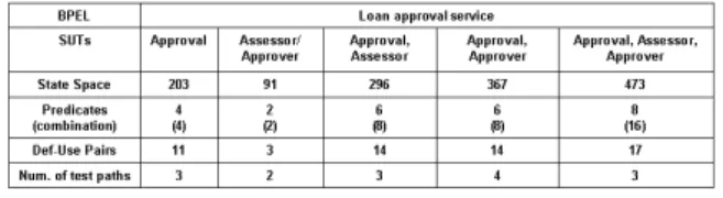
Fig 14 shows the summary when choosing different BPEL processes as SUT.
Figure 14. Multiple BPEL processes as SUT
Since state space explosion is the main issue of model checking techniques, in order to improve the performance of a model-checking based tool, it is essential to reduce the model state space. We have shown by case studies that our web service automaton can alleviate the state space explosion problem by introducing multiple input and output events to machine transitions. Also, our abstraction of message type, message value, and predicates helps to speed up the model checking.
B. Tool Support
Our test framework has been implemented as an Eclipse plugin, theBPEL test case wizard, which is a component of the DBEStudio for the EU project DBE [10]. The BPEL test case wizard consists of three components: the user interface, the transformation engine, and the model checker manager. The wizard allows the user to choose a BPEL process as the service under test (SUT), and choose the WSDL interface model. The partner web services of the selected BPEL process can be chosen as a component of the SUT. Then a model checker can be selected to verify the general properties and to generate test cases. Inside the test framework, the XSLT transformation engine manages the mappings between models, which is using Saxon’s XSLT 2.0 processor. For pre-processing, the engine manages the mappings for the model checkers, including BPEL-to-WSA, WSA-to-PROMELA, WSA-to-SMV. For post-processing, the engine manages the mapping from counterexamples to
transition sequences, and the mapping from transition sequences to test cases. The mapping to test cases is based on the transition sequence, the web service automata, and the WSDL description. The test cases are in JUnit test case format. Hence, the test cases can be run against the JUnit execution engine directly. The user allows entering the test input (data) via a user interface.
V. RELATEDWORK
The current formal semantics proposed for BPEL can be categorised under three branches: Petri-net, Process Algebra, and Automata.
A. Petri Nets based approaches
Web service algebra is proposed in [11] to define a set of web service composition operators. The authors use Petri nets as the formal semantics for the proposed web service algebra. The works of [12], [13] present Petri net semantics for the control flow of BPEL, with consideration of BPEL advanced features such as fault handling, event handling, and compensation handling. In [13], the tool BPEL2PN is developed to map BPEL code to Petri nets, and model checker LoLA is used to verify CTL temporal logic. The author of [14] extends the work of [13] by using Petri net to capture the global interactions between BPEL processes. In [12], the tool BPEL2PNML is developed to map BPEL to Petri nets, and a verification tool WofBPEL is used as the analysis engine. The paper discusses how to verify the activity reachability and some pre-defined BPEL constraints. As a summary, the above works abstract from data. As shown in our motivation example, it is important to consider BPEL data dependencies.
In [15], they claim to capture both BPEL control and data dependencies in CP-nets, and CPN tools can be used to verify the process. However, the paper only shows how to map a core subset of BPEL to CP-nets. There is no discussion of how to capture BPEL data dependencies, and no concern of modelling faults or compensations.
In [16], they use CP-nets as the process composition models, and apply CPN tools as the verification engine. BPEL skeleton code can be generated from the process composition model. In the CP-nets models, messages (events) and process variables are represented by tokens. Abstract colour sets are declared for the messages and variables such that each colour set is kept small to speed up the analysis. They also use an algorithm to automatically derive the conversation protocol, which is also CP-net based, from the process composition models. The conversation protocol in their context only models the interactions between the service consumer and the service provider, and hides the internal process details such as those providing data manipulation and interaction with other service partners. Instead of verifying the BPEL process, their work focuses on designing a correct CP-net based model and generating a BPEL skeleton process.
B. Process Algebras based approaches
Process algebraic service composition aims to intro-duce much simpler descriptions than other approaches. In [17], a two-way mapping is defined between BPEL and LOTOS, and the model checking toolbox CADP is used as the verification engine. The mapping from LOTOS to BPEL does not preserve the structure of a process, due to the expressive and flexible structure of LOTOS. The dis-abling operatoris used to capture the BPEL interruptions. In LOTOS, the processes communicate synchronously by rendezvous.
In [18], the process algebra FSP (Finite State Pro-cesses) developed by [19] is used for the BPEL semantics and the model checker LTSA [19] as the verification engine. The web service composition specification is modelled in an MSC (Message Sequence Chart), and the implementation is modelled in BPEL. Both MSC models and BPEL processes are translated into FSPs, such that the BPEL implementation can be verified against the MSC specification by trace equivalence checking. The work of [20] extends the earlier work to verify the interacting BPEL processes and checks their compatibility. A tool LTSA-WS was implemented as an Eclipse plug-in. FSP is abstract from data, so their mapping does not cover BPEL data dependencies. Also, FSP supports synchronous com-munication.
In [21], they use Pi-calculus as the BPEL formal model and NuSMV model checker as the verification engine. A tool, OPAL, is developed to automate the mapping from BPEL to Pi-calculus, and from Pi-calculus the input language SMV of the NuSMV model checker. It points out that there exist two approaches to model check Pi-calculus. One is to analyse Pi-calculus processes based on a proof system, and the other is to transform Pi-calculus into automata. The authors follow the second approach.
In [22], a language named CDL is proposed to extend WSDL to model the behaviour of individual web services. A composition language is also proposed, which can support both centralised and distributed orchestrations. The formal semantics of these two languages are based on Pi-calculus. They point out that the use of shared variables in BPEL makes it difficult to coordinate the execution in a distributed manner. Their composition language has two core concepts: a task and a process. A task is equal to a BPEL activity. For inter-task dependency, they explicitly consider control dependencies and data dependencies. They further point out that the current tool support for verification of Pi-calculus is immature. Most do not support the complete language and require a complex and error prone input syntax. A solution is to map Pi-calculus to the input languages of mature model checkers such as SPIN. Since the input languages of most mature model checkers are automaton-based, we believe an automaton-based formal model is more suitable for those input languages.
In the above Process Algebra approaches, they consider both the core BPEL activities and the advanced BPEL features with fault handling, compensation handling, and
event handling. However, since the BPEL scope based fault and compensation handling mechanism is complex, only a few works give it in-depth analysis. In [23], Puet al.propose a BPEL0 language to capture the BPEL scope based compensation handling features. They propose a n-bisimulation relation, which reflects the scope-based com-pensation mechanism, to define the equivalence between BPEL0 programs. An execution engine for BPEL0 is developed. In [24], Bulter et al. formalise the notions of compensation in a StAC language. They model the BPEL control flow using StAC and the model the BPEL data manipulation in B notation. The semantics is clean and precise, but it is not clear how to verify or test such models in an automatic way.
C. Automata based approaches
Automata provide a well-known formalism for sys-tem specifications. There are many different kinds of automata, including finite state machines (FSMs) such as Mealy and Moore machines. Label Transition systems are automata, which are generally infinite state.
In [25], BPEL models are mapped into deterministic finite state automata for the matchmaking of web service composition. The STSs (State Transition Systems) are used in [26] to be the BPEL formal semantics, and a tool is developed as a part of the ASTRO toolset [27]. Both of these formal models are abstracted from data.
In [28], they propose guarded automata (GA) to be the formal models for both BPEL and the conversation protocol. GA extends Mealy machines with data, and every transition is equipped with a guard in the form of an XPath expression. The model checker SPIN is used as the verification engine. BPEL processes communicate by sending asynchronous messages, and each process has a queue. A global watcher keeps track of all mes-sages. The conversation is introduced as a sequence of messages. They propose a set of sufficient conditions so that asynchronous communication can be replaced with synchronous communication. A tool WSAT is developed to map BPEL to guarded automata, and map guarded automata to Promela (the input language of SPIN). In their approach, each BPEL activity is mapped to a GA, so the BPEL process as a whole is a composition of a set of GAs. The interleaving semantics of concurrency is used. However, they omit the inter activity data de-pendencies. Also, in their models, the GAs representing BPEL processes communicate by message passing, but it is not clear how the GAs represents the BPEL activities communications. In our formal model, we believe it is clearer from the theoretical view to provide a single communication mechanism for both external and inter-nal interactions, where machines communicate by either message passing or by data sharing, but not both. In their mapping from GA to Promela, the XPath expressions in the GA transition guards are also translated into Promela, so that the data manipulation can be verified. We believe this will decrease the speed of model checkers, and that