Master Thesis
”Industrial jointed arm robot evading dynamic objects”
by:
Dipl.-Ing. (FH) Björn Ostermann
A thesis submitted to the
University of Applied Sciences Bonn-Rhein-Sieg
for the degree of
Master of Science in Autonomous Systems
Hochschule Bonn-Rhein-Sieg
Department of Computer Science
Master of Autonomous Systems
Grantham-Allee 20
53757 Sankt Augustin
Referee and Tutor: Dr. Michael Huelke Referee: Prof. Dr. Dietmar Reinert
Referee: Prof. Dr. -Ing. Gerhard K. Kraetzschmar
Master Thesis Björn Ostermann page 2 of 126
Acknowledgement
Several people have contributed to the success of this work, whom I’d like to thank at this point. I’d like to thank my colleagues at the BGIA, who contributed to this work by professional discussions and hints on important literature, as well as the construction of the robot’s workplace. Especially I’d like to thank my supervisor Dr. Michael Huelke for his constant support and Dr. Michael Schaefer for making this work possible.
Also I’d like to thank my supervising professors, Prof. Dr. Dietmar Reinert and Prof. Dr.-Ing. Gerhard K. Kraetzschmar, for their support and ideas on the improvement of the project.
I thank Jörn von der Lippe, who worked on a parallel master project on the same 3D camera, for tossing back and forth ideas on algorithms and programming (e.g. see chapter 5.2.1) for one and a halve year and for letting me reuse some of his code (e.g. see chapter 5.1.2).
Furthermore I thank the people at Reis GmbH & Co. KG Maschinenfabrik, especially Dipl.-Ing. Franz Som and Michael Pfeiffer, for their detailed information on their hard- and software and for contributing the robot, which was used in this project.
Master Thesis Björn Ostermann page 3 of 126
Statutory Declaration
With this I declare that the present Project Report was made by my self. Prohibited means were not used and only the aids specified in the Master Thesis were applied. All parts which are taken over word to word or analogous from literature and other publications are quoted and identified.
Björn Ostermann
Master Thesis Björn Ostermann page 4 of 126
Abstract
Most industrial robots used today work behind fences. Even in those cases where the fences are substituted by electro sensitive protective equipment (ESPE), the position of the separation between human’s and robot’s workspace is invariable.
This work presents an integrated solution that allows flexible human-robot workspace separation. The
algorithms, responsible for maintaining the separation, are based on the tracking of objects that enter the workspace. These algorithms are divided into proximity monitoring and path planning. The demonstrator, developed in this work, consists of a 3D Camera, an industrial jointed arm robot and a desktop computer.
The main part of this work focuses on the algorithms that evaluate the collected data and compute a collision free path for the robot. A software interface has been
developed, that finds intrusions in the robot’s vicinity and changes the robot’s path accordingly.
It is also shown, which integration level has been reached and which problems could not be covered in the course of this project. The applicability of such a system in praxis is discussed, depending on the current safety standards and available technology.
Master Thesis Björn Ostermann page 5 of 126
Contents
1
Introduction ... 8
1.1
Problem Formulation... 8
1.2
Task Description... 9
2
Overview on human-robot collaboration... 10
2.1
State of the art ... 10
2.2
State of science – Related Work... 11
2.2.1 Morpha ... 12
2.2.2 Phriends... 13
2.2.3 Simero ... 13
2.3
Overview of the project at the BGIA... 14
2.3.1
Path planning approach ... 14
2.3.2
Necessary algorithms and features ... 17
3
Description of the hard- and software... 19
3.1
Jointed Arm Robot Reis RV30-16 ... 21
3.2
3D Camera Mesa Swissranger ... 25
3.3
Workspace... 28
3.4
MS Visual Studio... 29
3.5
Robot remote control language ... 30
3.6
Control hierarchy... 31
4
Overall evading concept... 33
4.1
Tasks hierarchy ... 33
4.2
Graphical User Interface (GUI)... 35
4.3
Camera control thread... 36
4.3.1
Intensity and distance depiction ... 37
4.3.2 Background
acquisition... 39
4.3.3
Adjusting offset and intrusion filter ... 40
4.3.4
Region growing and reachable space computation ... 43
4.3.5
Determining the relations of the coordinate systems of robot and camera ... 46
4.4
Path planning control... 49
4.4.1
Basic work routine ... 50
4.4.2
Speed control and object avoidance ... 51
4.4.3 Collision
reset... 53
4.5
Robot control ... 54
4.6
Exchange of information between tasks... 56
5
Algorithms for robotic evasion... 59
5.1
Depicting the acquired information... 59
5.1.1
Histogram equalization – improving the grey scale values... 60
5.1.2
Converting distance to colour ... 64
Master Thesis Björn Ostermann page 6 of 126
5.2.1
Acquiring the background data ... 66
5.2.1.1 Kalman Filter ... 66
5.2.1.2 Gaussian blur ... 67
5.2.2
Finding intrusions and filtering ... 70
5.2.2.1 Offset filter... 71
5.2.2.2 Spike filter... 72
5.2.2.3 Plausibility filter ... 73
5.2.3
Adding a virtual robot base ... 75
5.2.4 Region
growing ... 76
5.2.4.1 Region growing by outlining and filling... 76
5.2.4.2 Region size filter ... 80
5.2.4.3 Distinguishing the robot from objects... 81
5.3
Detecting collisions ... 82
5.4
Robot speed control... 83
5.5
Robot path planning... 86
5.5.1
Calculating the distance between the current pose and the goal pose... 87
5.5.2
Transformation of coordinate systems ... 87
5.5.3
Determining the reachable space... 91
5.5.4
Selection of significant part... 93
5.5.5
Calculating the shortest evasion path ... 96
6
Evaluating the safety of the system... 100
6.1
Regulations... 100
6.1.1 Machinery
Directive
2006/42/EC ... 101
6.2
Standards ... 102
6.2.1
Safety of machinery – Safety distances to prevent hazard zones being reached
by upper and lower limbs EN ISO 13857:2008 (EN 294:1992)... 103
6.2.2
Safety of machinery – The positioning of protective equipment in respect of
approach speeds of parts of the human body EN 999:1998 ... 104
6.2.3
Safety of machinery – Safety-related parts of control systems – Part 1: General
principles for design EN ISO 13849-1... 105
6.2.4
Robots for Industrial Environment – Safety requirements – Part 1: Robot EN
10218-1 ... 107
6.3
Achieved safety ... 108
6.4
Desired safety... 113
6.5
Comparison of achieved and desired safety... 114
7
Conclusion and Outlook ... 115
7.1
Conclusion... 115
7.2
Outlook... 116
8
Bibliography... 118
8.1
Paper on human robot interaction ... 118
8.2
Paper on path planning algorithms with industrial joint arm robots... 120
8.3
Paper on filter algorithms... 120
Master Thesis Björn Ostermann page 7 of 126
8.5
Internet... 120
8.6
Books ... 121
8.7
Lecture Slides... 121
8.8
Laws and Regulations ... 121
8.9
Internal Documents... 122
9
List of Figures ... 123
1. Introduction Master Thesis Björn Ostermann page 8 of 126
1
Introduction
The first industrial jointed arm robot was invented in 1954 and first used in 1962 for industrial production [64]. At the end of the year 2008 the IFR Statistical Department, a group hosted by the VDMA (association of German machine and machinery manufacturer) [59], estimates the amount of operational industrial robots at over one million [58]. About 140,000 of those robots are estimated to be in use in Germany [58].
Due to the regulations of European law and standards, most of those robots work behind rigid fences to ensure the safety of human operators in the vicinity. With the approval of laser scanners for safety applications in 1998 [60] and SafetyEye [47], a camera system, in 2006, some fences have been replaced by electro sensitive protective equipment (ESPE), but the rigid borders between human and robot still remain.
The constantly increasing demand for the possibility of collaborative tasks, according to [70] a cooperative task between human and robot, also increases the demand on systems with less rigid separation mechanisms. Experimental research to free the robots from their fences started in the 80s [3], after the first death related to a robot accident occurred in 1982 [1]. Although the number of projects working on this topic is constantly increasing, until today no application is known to be approved for industrial production.
The work on the presented project started in 2007. Earlier studies [77] provided an insight into possible approaches towards the mechanisms of human robot collaboration. As a result from those studies a new approach to the problem was formulated and tested [78].
This project describes the new approach, a flexible borderline control of “human-robot workspace separation”, and shows its implementation into a demonstrator at the BGIA – Institute for Occupational Safety and Health. The demonstrator consists of a 3D time of flight camera, a jointed arm robot with a safety control system and a PC. The data collected from the camera and the robot are processed in the PC, with the result that the robot evades persons and objects.
1.1
Problem Formulation
Robots in today’s industries work behind fences. This reduces their field of application, especially when collaboration between humans and robots is needed.
Certain approaches towards a free robot have been made already, but until today, no practical solution usable in praxis is known.
The BGIA, hosting this project, is a leading research institute in the case of industrial safety related applications. One important goal of the division “Accident Prevention / Product Safety” is to find a solution for the problem that allows maximum flexibility of the robot with minimum risk to the human operators.
1. Introduction Master Thesis Björn Ostermann page 9 of 126
Humans usually do not feel comfortable working alongside a robot without physical borders. Therefore, as a secondary goal, a method has to be found, that increases the trust in a freely accessible system.
1.2
Task Description
The goal of the framework project, consisting of this project and previous work [77] [78], is to provide a demonstrative workplace, showing an industrial robot working in flexible boundaries while evading dynamic objects.
The workplace set up in this project is to be demonstrated with real human operators.
To achieve the necessary safety, the robot is only allowed to drive at a safely monitored speed under the constant supervision of a human operator. This allows the use of equipment that does not fulfil the safety standards needed in real industrial automatic production. Therefore this work is only a feasibility study and not designed at this stage for industrial production.
The required hardware, a robot, a sensor and a logical unit, was chosen in the previous work [78], where they were handled separately. In this work the hardware is to be combined in order to act as a unit. Therefore a controlling software program is to be developed, which implements and tests the desired flexible boundaries.
On the software side, algorithms of previous work [77], have to be implemented and tested. Where those algorithms lack feasibility or completeness, new algorithms have to be designed, implemented and tested. The performance of the developed solution has to be shown, with respect to the safety of the system.
On the hardware side, a 3D camera provides data about the workspace which have to be evaluated by a controlling program running on a PC. Based on the analysis of the acquired 3D data the program has to send commands to the attached robot, controlling its movements. The optimal spatial arrangement of the hardware has to be determined and realized. The spatial arrangement of the 3D camera thereby has to be flexible, to test different perspectives on the workplace.
Additionally to the functional demonstrator, a depiction of the acquisition and analysis of the data has to be programmed that allows a live observation of the single steps of the program.
2. Overview on human-robot Master Thesis Björn Ostermann page 10 of 126
2
Overview on human-robot collaboration
2.1
State of the art
Since the invention of the joint arm robot in 1954 by George Devol, founder of the company Unimation, and its first usage in 1962 by General Motors [64], humans have been separated from industrial robots to assure their safety. Until the end of the 20th century this separation was achieved by rigid fences.
A major step towards a fenceless workplace was achieved in 1996, when the sourcecode SICK programmed for lasercannes was approved or safety related applications [60] by the BGIA, and later in 1998, when the first laser scanner, the PLS 101-312 by SICK, was approved for safety related applications [60] by the BGIA.
The next step was achieved in 2006, when the company Pilz GmbH & Co. KG introduced a system, called SafetyEye [47], which is based on cameras (see Figure 1).
With respect to safety, both systems, laser scanner and SafetyEye, can differentiate between three different situations. Therefore their field of view can be separated into non protective and protective fields. The protective field thereby is separated into a warning and a safety area. If there is no object in the protective field, the robot is fully functional. If an object enters the warning (yellow) area, the speed of the robot is reduced, and if an object enters the safety (red) area, the robot is stopped.
In case of the SafetyEye, no action is taken for objects in the working (blue) area, since intruding objects can not be distinguished from working material or the robot itself.
Although laser scanner and cameras allow easy changes of these boundaries between production cycles, during production the human and the robot are still separated by a nonflexible invisible fence, and no real collaboration is possible.
SafetyEYE
Protective Field
Robot
Robot’s working space
2. Overview on human-robot Master Thesis Björn Ostermann page 11 of 126
2.2
State of science – Related Work
The first approaches on safe interactions of humans and industrial robots were made in the 80s. After the first death of a worker related to a robot accident, reported in 1982 [1], safety studies in 1983 concluded that a robot could only be safe if the robot could detect the approach of a human and react accordingly [2].
In 1985 [3] Graham and Meagher of the Rensselaer Polytechnic Institute in New York investigated microwave, ultrasound, infra-red and capacitive sensors on their applicability in collaborative workplaces. They continued their work, together with Derby, in 1986 [4] resulting in the conclusion that “much research still needs to be done on robotics safety”. The Rensselaer Polytechnic Institute is still working in the field of safe robot-human collaboration. In one of their latest projects from 2007 [5] Meisner, Isler and Trinkle used a galvanic skin response sensor, measuring the workers stress level, to generate robot trajectories.
In 1989 [6] Takakura et al. outfitted a robot with torque sensors and programmed an algorithm that worked on contact sensing and memorization of objects. Although this approach was not feasible in praxis, due to the reduced speed of the robot, in order to avoid any damage by collisions, and problems with dynamic objects, whose changed positions can not be tracked, the idea of using torque sensors persists until today (see chapter 2.2.2).
In 1992 and 1994 Novak and Feddema used capacity sensors for object avoidance [7]. The advantage of this approach is that the robot does not need to touch the obstacle, but can sense it in its vicinity. While increasing the sensor range from touch to close vicinity was an improvement, the problem in this approach is the different reactions of capacity sensors to different materials.
Ebert and Henrich presented in 2002 a solution that used a multiple camera system to detect collisions between the robot and obstacles [10]. The problems they reported for this approach existed in cells being reported as occupied while free and vice versa and in the robot blocking the view of the cameras in certain positions. In later projects by Henrich this problem has been reduced but not completely solved (see chapter 2.2.3).
Heiligensetzer and Wörn demonstrated in 2002 [20] [21] a Kuka Robot, equipped with capacity proximity sensors and haptic devices. Heiligensetzer continued the approach, using capacitive proximity and tactile sensors, in 2004 [19] and 2007 [57]. A problem in approaches using force sensors is always the reduced speed of the robot, which is necessary to avoid harm to humans. The robot presented in 2007 was therefore also equipped with collision absorbing material, making it possible to detect a collision before harm is done to the worker. Wörn continued his work in this field in 2004 [22], together with Yigit and Burgart, by developing a reflex based control for industrial robots, in which reflexes take over the control if a dangerous situation is detected.
2. Overview on human-robot Master Thesis Björn Ostermann page 12 of 126
In recent years the primary focus in the field of safe industrial robot collaboration was on the force sensors, which detect only collisions, and on camera based solutions. In 2005 [17] Lu and Chung presented a wrist force/torque sensors using robot, equipped with a weighted path planning algorithm. The DLR lightweight robot [16] presented in 2007 allows torque sensing in its joints, which makes fast collision based planning possible.
In 2007 F. Som, Manager Control Development Software – REIS Robotics, presented an approach with a 3D camera mounted to the ceiling that observes the roboter’s working environment [56]. Little information was given on the used hardware and algorithms, as well as on the state of the project, but individual communication with Mr. Som showed that the hardware set-up of the approach from REIS is similar to the set-up of the approach developed in this master thesis. Differences exists in the handling of the acquired image data. For example REIS is trying to eliminate the robot for further calculations by knowledge of its position, while this master thesis identifies the robot but keeps it in the acquired data because of safety reasons.
Among other problems, camera based solutions suffer from occlusions of objects by other objects in the workplace. This is a problem independent from the chosen approach, whether 2D data or 3D data is acquired from the sensor system. Thus in recent years the number of studies on combining several data sources has increased. In 2008 Elshafie and Bone [14], Mure and Hugli [24] and Lenz et al. [25] presented solutions to this problem. Also the number of systems that try to anticipate human behaviour, as shown by Lenz et al. [25], is increasing.
Another approach to the problem that has come up is equipping the human with sensors, rather than the robot. This was shown by Meisner et al. [5] in 2007, as described above, and also by Tamei et al. [26] who used a surface electromyogram in 2008 to simulate force sensors on the robot from the data collected at the human body.
2.2.1
Morpha
From 1999 to 2003 the research project MORPHA was conducted [50]. The goal of this project was the interaction, communication and collaboration between humans and intelligent robot assistants. In the course of the project, several approaches on the given topic were presented.
As one of the first results on industrial robot arms from this project Wösch and Neubauer showed in 2001 an eight degree of freedom robot with a stereo camera system, a laser scanner and a tactile sensor skin that could evade humans [8]. They used real forces, measured by the tactile skin, as well as virtual forces, induced from the model of the environment, to move the robot arm away from objects. In the MORPA project "rob@work" in 2002, Helms, Schraft and Hägele used a camera mounted at the ceiling and a 3D laser scanner behind the working place, to achieve a collaborative workplace of a human and an industrial robot arm [9]. The robot arm was mounted on a mobile platform and could thus be transported to other workplaces, while the camera and 3D laser scanner were stationary.
2. Overview on human-robot Master Thesis Björn Ostermann page 13 of 126
While the camera was used to detect humans in the workspace and reduce the robot’s operation speed in the near vicinity of the human, the 3D laser scanner results were used for path planning. Due to the usage of only one 3D scanner, the robot arm induced blind spots in the environment.
Also a contribution to MORPHA was made in 2004 by Stopp et al. [11]. They used multiple laser scanners and a 360 degree overhead camera on the DaimlerChrysler Manufacturing Assistant, a normal industrial robot by Reis GmbH & Co. KG Maschinenfabrik, mounted on a mobile platform. The software created static and dynamic protective fields, based on the current task and position, which caused the robot to slow down if approached, up to the point of standing still without an emergency stop. The system also included a force sensor in the endeffector that allowed the program to detect, if a human was trying to acquire the object currently held by the robot, in which case the object was released.
2.2.2
Phriends
From October 2006 till September 2009 the Phriends (Physical Human Robot Interaction – depENDability and Safety) project [45] is conducting research on physical human-robot interaction. The DLR (German Aerospace Center) and KUKA Roboter GmbH, both participants in the MORPHA project, also take part in this project. Part of this work is the investigation into the field of safe interaction of humans and robots without any separation in time or place. To acquire this grade of collaboration the robot has to be outfitted with force sensors.
A first result of this project is the KUKA lightweight robot [53]. This seven degrees of freedom industrial joint arm robot is equipped with integrated sensitivity sensors, that allow the robot to follow human guidance and detect impacts. Impact tests at 2m/s were conducted, which show that the robot combined with its control does only minimal hurt to the human body.
At present the Phriends team is working on solutions using two 2D cameras, one to observe the area and one mounted to the robot for close observation.
2.2.3
Simero
Safety strategies for human-robot-cooperation (SIMERO [51]) is a project of the University of Bayreuth. This project is supervised by Prof. D. Henrich and based on his approach [10] from 2002. The sensor used in this project is a multi 2D camera system, where all cameras are placed strategically in the working area. The different angles of the camera were chosen to minimize the occlusion by dynamic objects and the robot itself. This allows the robot to evade the human horizontally and vertically.
While some problems have been solved during the course of the project, in 2008 changes in the lighting conditions in the environment still cause difficulties. Along with pre-processing cameras and a new approach on path planning, these difficulties will be addressed in the future work of the project [13].
2. Overview on human-robot Master Thesis Björn Ostermann page 14 of 126
2.3
Overview of the project at the BGIA
Prior to this master thesis two project reports have been created [77] [78], which have laid the foundation of this thesis and their results are included in this report.
This chapter summarizes the complete framework project, consisting of both reports and this thesis. The overall goal of the complete project is to develop a collaborative workspace, consisting of an industrial jointed arm robot, a sensor system and a control system that allows a human operator to work safely in close proximity of the robot.
In the R&D 1 report: “Development of a prototype of an autonomous motion control for assisting industrial robots” [77] several approaches to this topic were evaluated (see chapter 2.2) and a solution to the topic was developed.
At the beginning of the R&D 2 project the developed theoretical approach to the above mentioned solution was discussed on the point of feasibility. An optimal tradeoff between functionality and feasibility was found, which is briefly described in chapter 2.3.1, along with the different algorithms in chapter 2.3.2 that are needed for the completion of the project in this master thesis.
The hard- and software, discussed in the R&D 1 report, on which the project is implemented, was selected in the R&D 2. A description of this hard- and software, as well as its assembly in this master thesis, can be found in chapter 3.
The main attention of this report is on the designed program that shows how the robot can be controlled to evade dynamic objects in its working place. Additionally, in chapter 6.4, the performance of the system is evaluated and compared to an optimal system.
2.3.1
Path planning approach
As described in the previous R&D 1 report [77], there are several modes of safe human-robot collaboration that can be achieved. The easiest is to separate the human and the robot completely, thus allowing no cooperation at all. The most difficult is to allow the human and the robot touching each other, while still executing tasks. To collaborate with a human, robots have to sense their complete environment and act accordingly, because safety, mainly of the human operator, is always the biggest issue.
The approach described in the R&D 1 report has been designed to allow a high degree of collaboration between human and robot, enabling the human to touch and interact with the robot at all times. This approach not only puts high demands on the required hardware, using for example at least two high tech 3D cameras, but also needs a lot of computational effort, which in turn puts high demands on the processing capabilities of the logical unit.
Based on the knowledge, acquired in the first report, a practical approach was found. This approach is a tradeoff between the functionality of the previously developed algorithm and the simplicity of a fence. It was develop in the R&D 2 report [78] and can best be described as a flexible fence. Human
2. Overview on human-robot Master Thesis Björn Ostermann page 15 of 126
and robot are still separated, but the human is allowed to enter the robot’s working area. The robot is working around the human or, if no alternative path is available, waiting for the human to leave the occupied path.
The flexible fence is realized with only one 3D camera, mounted above the robot and looking downward at the working area, as depicted in Figure 2.
Camera
Robot Working Area
Robot
Figure 2: Assembly of the workspace
Since the camera delivers distance information for each observed pixel, the knowledge about an intruding dynamic object can be build by comparing the distances measured in the empty workspace (background image – see chapter 5.2.1) with the distances currently observed in the workspace. An intruding object is recognized through its lower distance values.
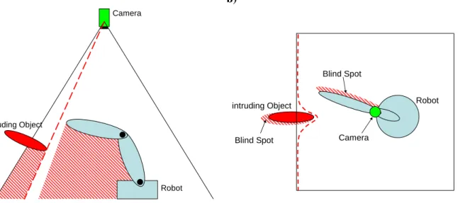
As long as there are no intruding objects, which might be dynamic or stationary, in the working area, the robot can execute its normal tasks. If objects intrude into this guarded working area, the space they occupy has to be excluded from the robot’s possible movement. This reduced space is depicted by the red dashed line in Figure 3.
2. Overview on human-robot Master Thesis Björn Ostermann page 16 of 126
a) b)
Camera
Robot intruding Object
Blind Spot Blind Spot
intruding Object
Camera
Robot
Blind Spot
Blind Spot
Figure 3: Camera’s view on the working space a) from the side and b) from top
The blind spots below the intruding objects, as well as below the robot itself are problematic. The camera can not observe the area within those blind spots. From the knowledge of the robot’s physical dimensions and the past distance values observed by the camera, showing the static background, it can be assumed, as long as the blind spot of the robot has not been connected to any other blind spot, that the space below the robot is still free of new objects. Therefore a path planning algorithm can plan the robot’s path accordingly. If those blind spots would connect at any time, the knowledge about the static background can no longer be used, since a new dynamic object could have entered the robot’s blind spot via the blind spot of the detected dynamic object.
For path planning this leads to the restriction that the robot may never work in the blind spot of a detected object, since this space can not be monitored. It also may not cast its own blind spot on intruding objects or touch the object, since the blind spots of the robot and the intruding object would otherwise merge. At this point the blind spot below the robot can no longer be considered free of objects, since other objects can pass from one blind spot to the other, without being detected. Theoretically, if this would happen, the robot could only be allowed to move upwards, towards the camera. The problem in this case would be that the monitoring of the workspace below the robot can no longer be deduced from history. The knowledge of the workspace below the robot is lost. To insure safety, the robot’s motions are stopped in such a case. The robot’s workspace needs to be checked manually by the human operator. After a successful inspection the operator can allow the robot to continue.
As an additional approach, it is possible not to control the robot’s trajectory, but only its speed in accordance to the robot’s distance to an intrusion. This approach can be based on the same data acquired by the 3D camera. It has a lower rate of productivity, since the robot is not avoiding obstacles
2. Overview on human-robot Master Thesis Björn Ostermann page 17 of 126
but stopping and waiting in a safe distance from the intrusion. Its advantage is its simpler realisation, which can be easier verified for freedom from errors.
Both approaches can be combined. In this case, only the distance measurement needs to be approved for safety related work. The robot can not collide with any object due to path planning, if its approach on those objects is monitored. The functionality of the path planning algorithm is then only relevant for the performance of the process.
2.3.2
Necessary algorithms and features
To complete the given task several sub-goals had to be reached. The developed and applied solutions are described in chapter 4 and 5.
There is no interface available from the manufacturer that allows the control of the chosen industrial robot with a C++ program. To remotely control the robot, only a set of XML (extended markup language) commands are available (see chapter 3.5 and chapter Fehler! Verweisquelle konnte nicht gefunden werden.) that have to be sent to the robot via TCP/IP. From those XML commands an own C++ interpreter had to be created. The XML commands are limited in their amount and can not be extended by the user. The robot needed to be controlled with relative and absolute positioning commands, but the relative positioning commands are not supported by the given XML commands. The solution to the relative control was achieved in the R&D 2 project [78]. In this master thesis the C++ library of the commands implemented in the R&D 2 was created (see source code on CD).
The chosen 3D camera delivers a set of image data, containing the distance of objects and their reflectivity in the used near infrared spectrum. The image data delivered by the 3D camera can not be interpreted by a human observer. The values of reflectivity are usually very close to each other, resulting in a mostly black image when depicted in greyscale, and thus have to be enhanced, in order to depict an understandable image. The distance data need to be interpreted by the program as well, to show an understandable image.
The optical analysis by a human observer is not only necessary for the development process of the final program. The illustration of the correctly working algorithm next to the robot can, especially at the introduction of this new technology, also enhance the operators trust in the developed concept. Algorithms for the reflection image as well as the distance image have been developed in previous work [78] and combined in this thesis with highlighting algorithms that show the robot, dynamic objects and the flexible border or the distance between robot and object, depending on the chosen algorithm.
From the distance data, delivered by the 3D camera, the background of the empty workspace has to be acquired as a reference image, in order to be able to find intrusions later. Those intrusions have to be distinguished into robot and other objects. Problems in this area are mainly induced by the fluctuation noise, present in the acquired distance data. In order to achieve the desired goal, filters had to be tested and implemented, which reduce the fluctuation noise as much as possible.
2. Overview on human-robot Master Thesis Björn Ostermann page 18 of 126
From the data about the robot’s actual position and the actual position of all other intrusions, a speed control and a path planning has to be developed.
3. Hard- and software Master Thesis Björn Ostermann page 19 of 126
3
Description of the hard- and software
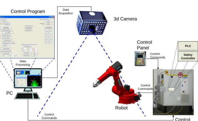
To achieve the desired goal, a robot avoiding dynamic objects, in addition to the robot further hard- and software is needed, as Figure 4 shows.
PC
3d Camera
Robot Control Program AcquisitionData
Data Processing Control Commands Control Panel Control Commands Control Commands Control Cabinet PLC Safety Controller
Figure 4: Hard- and software, necessary for the approach from chapter 2.3.2
The complete assembly consists of: - robot
- control cabinet, housing the robot’s programmable logic controller (PLC) and a safety controller - control panel
- 3D Camera - PC
- controlling program
The controlling program, running on the PC, is collecting data from the 3D camera, build by Mesa Imaging AG, processing this data and sending controlling commands to a PLC according to the computed results. The PLC controls the robot, as long as the control panel sends an approval signal. All the time, the reduced speed of the robot is monitored by the Esalan-SafetyController, by ELAN, which was developed in cooperation with REIS and the BGIA [54].
A detailed diagram, showing the connection between the PC and the robot, respectively the PC and the camera, can be found in chapter 3.6.
3. Hard- and software Master Thesis Björn Ostermann page 20 of 126
To select appropriate hard- and software for the project, several considerations have been made: - Robots, used in today’s industry, exist in many shapes and sizes. Since most of the industrial
tasks that require human-robot collaboration also require a high degree of freedom (DoF) of the robot’s endeffector, a jointed arm robot was chosen for this project. Since a six DoF joint arm robot is the most common joint arm robot in the manufacturing industries, it is the most reasonable choice. The robot chosen for the project was a RV30-16 by REIS.
- If the wrong commands are given, this robot might be dangerous to its environment and itself. Therefore it is reasonable to simulate its behaviour prior to the implementation in praxis. For simulating the robot’s behaviour, when controlled by the PC, the simulation-software RobOffice 20.3, developed by REIS, was used throughout the whole project. This software behaves in most points similar to the robot and gives a good anticipation of the final results. Since some deviations do exist, routines worked out with the simulation have to be carefully rechecked on the real robot.
- Since finding a path for a joint arm robot is a task in a three dimensional room, the sensor results should also be three dimensional.
The sensor’s range must be appropriate to cover the complete workplace.
The safety distance between robot and human is directly connected with the measuring time of the sensor. Thus the measuring time should be as short as possible to reduce the required safety distance to a minimum.
The best achievable results are yielded by 3D sensors like the 3D laser scanners used in previous approaches in this field of science or 3D cameras, whose results are more inaccurate, but which are considerably faster. Since the speed of the 3D laser scanners is not fast enough at this point, this project is based on a 3D camera. The chosen sensor is the 3D Camera by Mesa Imaging AG, the Swissranger SR-3100.
- It is common to communicate with a robot using an XML language (see literature in chapter 8.4). There are several common languages proposed by different applicants from the robotics industries, for example XIRP supported by the VDMA (see [38] and [39]) and RoboML (see [41] and [43]), but until today no common structure for this language is standardized. The XML-language used in this project, RSV COMMAND XML, is specified by the robot’s manufacturer REIS.
- The camera’s manufacturer only supports a C++ library for the connection of PC and camera. Since the functions contained in this library change with the version of the library, an interpreter was programmed during this project that allows exchanging the library with as little effort as possible.
3. Hard- and software Master Thesis Björn Ostermann page 21 of 126
- The program, developed in this project has to be able to acquire data from the camera and the robot and process this data in real time.
The XML commands controlling the robot are send via TCP/IP and sockets, which gives a lot of freedom of choice for the programming language and the system.
The camera’s C++ library and the fact that C++ can work with sockets and is also known to be considerably fast in execution, makes C++ the logical choice as the programming language. - To achieve the best possible result in case of real time execution the program was executed on a
multicore processor. To make the best usage of the processor, the program was separated into several tasks. With C++ this can be achieved easily using the .NET framework, which is supported by MS Visual Studio 2008 Express.
- The operator at the robot has to be able to see the results of the algorithms, enabling him to visually control their operation. OpenCV, a free library containing algorithms for graphical analysis and image creation, was chosen for the depiction of the images, created by the program.
3.1
Jointed Arm Robot Reis RV30-16
A jointed arm robot resembles the arm of a human and has similar degrees of freedom (DoF). While the human arm has 7 DoF, most robot arms, like the RV30-16, only have 6 DoF, since those are enough for the robot’s endeffector to reach any pose (position and orientation of the endeffector) within its working space. That means that all X, Y and Z coordinates and all Alpha-X, Beta-Y and Theta-Z angles can be reached.
Figure 5 shows the RV30-16 by Reis and Figure 6 shows the kinematics for this jointed arm robot.
1
2
3
4
5
6
3. Hard- and software Master Thesis Björn Ostermann page 22 of 126
rotational joint
robot arm
robot base
endeffector
1
2
3
4
5
6
Figure 6: RV30-16 kinematics – upper right arm configuration
The six rotational joints in Figure 6, also called revolute joints, are grouped based on two conditions. One condition is whether their rotation changes the position of the next arms endpoint or not. The other condition is whether it changes the next arms rotational angle or not.
- Joints 2, 3 and 5 only change the position of the next arm’s joint. - Joint 4 only changes the angle of the next arm’s joint.
- Joint 1 changes both, the position and the angle.
- Joint 6 depends on the endeffector (the tool), that is mounted on the robot’s arm. If the tool centre point is centred on the axis of joint 6 only the angle is changed (same as joint 4). If the tool centre point is outside of the axis of joint 6, the position is changed as well (same as joint 1).
The robot’s kinematics results in two methods for position calculation, the forward kinematics and the inverse kinematics.
The forward kinematics handles the question of the endeffector’s position, given specific angles of the joints. This problem always yields one specific solution for each set of angles.
The inverse kinematic is a more complex problem. A six degree of freedom robot arm has up to eight different possibilities to reach most endpoints, in special points, singularities, a multitude of possibilities exist (see below). The six configurations are the right arm configuration or the left arm configuration, each combined with the upper or the lower arm configuration and the flip and no-flip position.
3. Hard- and software Master Thesis Björn Ostermann page 23 of 126
The robot depicted in Figure 5 and Figure 6 is positioned in an upper right arm position. Right arm position means his second joint is on the right side of the first one. The upper part is from the fact that joint three is above the direct line from joint two to five.
If the robot’s first axis is turned by 180° and flipped over by turning axes two and three, the same position could be reached with the left arm configuration. From both configurations the lower arm configuration can be achieved, by turning axes two and three. Figure 7 shows the kinematics for a robot in lower left arm configuration.
rotational joint robot arm robot base endeffector
1
2
3
4
5
6
Figure 7: RV30-16 kinematics – lower left arm configuration
Flipping is achieved by the axes four, five and six. If axis four is turned by 180°, half a circle, axis five is flipped to the other side and axis six is turned by 180° as well, the same position as before is reached.
The path of the robot, defined by a start- and an endpoint, can be executed in two different ways. Since both positions are defined by the angles of the robot’s joints, the easiest way to reach the endpoint is to simply change every angle simultaneously, calculating the changing speed from the longest changing time in all angles. This calculation can be achieved by applying a factor to the maximum possible speed of the angle, as shown in Equation 1.
3. Hard- and software Master Thesis Björn Ostermann page 24 of 126
t i t i
n t n t n f start end i start end 6 1 maxEquation 1: Calculating the factor f for the speed of the individual angle n according to the description in [76]
nf factor to be applied to maximum speed of angle n
n
t
start start time of movement for angle n
n
t
end end time of fastest movement for angle nThe other, more complex, method to move the robot’s endpoint from one position to another is to calculate a straight path between those points. To achieve this, the desired line is separated into small changes and for every such change the angles of the axes are calculated, using inverse transformation. Afterwards the results are connected by interpolation. Thus, the more points are used, the higher the accuracy of the path.
Moving on a straight path can cause problems, if singularities exist in the calculated path. Singularities are special points in the robot’s workspace where two or more joints are collinear (joint four and six in the shown configurations in Figure 6 and Figure 7). In those points a multitude of possible configurations exist (see [70] chapter 3.23). The singularities can cause problems when they exist in a calculated path, because the robot might have to change the arms configuration (e.g. from flip to no flip), which can not be done instantly. Thus the robot has to stop at such a point, which in turn can be bad for the process (e.g. in special welding cases).
While being one of the smaller Reis robots, the RV30-16 can still handle up to 16 kg, which should be enough for demonstrative purposes. Also the speed of the robot, which can be up to 4 m/sec is sufficient for this task.
The robot is also equipped with electronic safety trips [48], designed by REIS. These trips monitor the position of all of the robot’s joints and shut down the robot, if any joint malfunctions. Malfunctioning can be a diversion from the parameters transmitted by the robot’s PLC, a dangerous increase in the joints speed, e.g. while driving through a singularity, or entering of a zone that has been prohibited in the setup phase of the trips. Finally, the trips guaranty that the robot’s endeffector is at the desired position.
3. Hard- and software Master Thesis Björn Ostermann page 25 of 126
3.2
3D Camera Mesa Swissranger
The chosen camera, the Mesa Swissranger SR-3100 (see Figure 8), is a Photonic Mixer Device (PMD).
Figure 8: Mesa Swissranger SR-3100 [55]
PMDs are based on the principle of measuring the distance by the phase difference of an additional amplitude modulation (see Figure 11) between the emitted and the received light.
All PMD devices are equipped with an own light source. Figure 9 shows the camera’s own LEDs emitting light at a certain wavelength, near the infrared range. This light is reflected by objects, loosing intensity in the process dependent on the reflecting surface. A filter in front of the camera’s sensor subtracts any but the emitted wavelength (see [55]).
Camera
Object
LEDs
Lens and Filter
Figure 9: Camera emitting near infrared ray (blue) and receiving reflected ray (orange)
The camera’s internal electronic can measure the phase shift between emitted and received light, depicted in Figure 10, resulting in a “Time of Flight” (ToF) measurement of the light wave.
3. Hard- and software Master Thesis Björn Ostermann page 26 of 126 Amplitude Time Phase-Shift Loss in Amplitude 1.5*
Figure 10: Example of a Phase Shift between two waves
By this ToF and the constant speed of light the distance from the camera to the object can be deduced. Since this measurement is done in every pixel of the camera’s sensor chip, a two dimensional image of distance information is gathered, equal to the human depth perception.
As long as it is constant and above the measuring threshold, the percental loss in amplitude between the emitted and received light has no effect on the distance measurement. This loss can be used to generate additional information on the received objects, which are normally displayed as a black to white reflection image. Since the filter in front of the camera’s sensor filters out any light but the emitted near infrared light, this image does not show the “normal” greyscale values, but the reflective properties of the viewed material to this specific wavelength. Thus the actual colour of the objects can not be recovered from this image, since there is no strong correlation between the object’s colour and its reflectivity.
The disadvantage of using phase shift to measure the ToF is the limited range. Since the phase of the light wave repeats itself after approximately 800nm the range would be limited to 400nm, half a wavelength. This is why the amplitude of the emitted light is modulated as well (see Figure 11), generating a second wave, to increase the range to about 7.5 meters.
Amplitude
Time superimposed amplitude wave
Figure 11: Generating a superimposed wave by amplitude modulation
To achieve a range of 7.5 meters, the modulation of the amplitude needs to be at 20MHz, as shown in the formula in Equation 2.
3. Hard- and software Master Thesis Björn Ostermann page 27 of 126
range
camera
2
1
f
c
m
MHz
2
7
.
5
1
20
s
m
458
792
299
Equation 2: Calculation of the maximum range
c being the speed of light
f
being the used modulation frequencyLonger ranges would theoretically be possible by choosing other modulation frequencies. Due to the physical restrictions of the used sensor chip (saturation time, etc.) 7.5 meters is the maximum range for which the camera is usable, according to the manufacturer [55].
The advantage in using near infrared light is that the every other part of the spectrum, including the visible light, can be filtered out before measuring.
The camera’s main characteristics are summarized in Figure 12, additional information can be found in the first project report [77].
Model No. SR-3100
Pixel array resolution 176 x 144 pixels
Field of view 47.5 x 39.6 degrees
Non-ambiguity range 7.5 m
Frame rate Variable, max 50fps
Estimated Error 1% of measured distance
Figure 12: Table containing Camera Data, taken from [55]
As shown in the first project [77], recognition of the humans hand is assured for a distance of up to three meters.
Detailed studies on the accuracy of the camera have been done by another BGIA project [80]. Their result is that the camera’s accuracy does not depend on temperature in a range between -10°C and +50°C. The camera delivers sufficiently reliable and repeatable results in a distance between 2 and 5 meters, provided that no material is present that does absorb most of the emitted light wave.
In the studies of this project only two materials (a grey jeans and a black shirt) have been found that do not reflect the emitted waves sufficiently. In the case of the given application, this problem can be handled as described in chapter 7.2.
3. Hard- and software Master Thesis Björn Ostermann page 28 of 126
3.3
Workspace
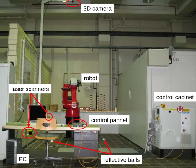
The Workspace used to implement and test the developed program is located in a laboratory of the BGIA, St. Augustin. The workspace is surrounded on three sides by walls which are more than 2.70m high (see Figure 13). According to the standard EN ISO 13857 [73], it is not required to have any distance between the robot and the walls, in order to secure human operators from reaching into the robot’s working area.
3D camera
laser scanners
PC
control cabinet
robot
control pannel
reflective balls
Figure 13: Workspace in the BGIA
Towards the frontal opening, the workspace is protected with two SICK laser scanners, which monitor the whole workspace. The laser scanners are positioned in such a way, that the robot is stopped, before an operator can reach the hazardous area. These scanners are active if the robot is controlled by the robot’s PLC alone, i.e. during the automatic mode of operation. In this project, the PC can only take over the control of the robot, if the robot’s control panel is set to “adjusting”. In this mode the scanners are muted by the robot’s so called safety controller (see chapter 3.1) and the safety is ensured by a hold to run button at the control panel during operation. Additionally in this mode of operation the speed of the tool centre point is reduced by its PLC to a speed of 250mm/sec which is safely monitored by the robot’s safety controller.
3. Hard- and software Master Thesis Björn Ostermann page 29 of 126
To protect the robot from harming any other equipment, protective zones have been implemented in the robot’s safety controller and in the configuration of the electronic safety trips.
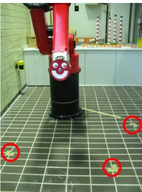
The 3D camera is mounted to an arm that is flexible in its horizontal and vertical position. This allows fixating the camera in a height between 4m and 5m. Because of the given workplace setup in this project, where little demonstration can be done to the side and behind the robot, the camera was mounted in front of the robot, to increase the covered working area in the frontal location. This has to be noticed in the risk assessment of the project (chapter 6.3) since the camera does not cover parts of the working range behind the robot.
If the position of the camera was changed, a new setup is needed, in which the camera is adjusted to the robot (see chapter 5.5.2). For this adjustment three reference blocks are used, which are balls covered in highly reflective material. The exact positions for the reference blocks have been determined during the programming phase of the project. These positions have been marked on the ground, so that the reference blocks themselves can be removed from the working area after the adjustment is completed (see Figure 14).
Figure 14: Robot working place with reflective balls (red circles)
Later versions of this project can use an adjustment program as described in chapter 7.2.
3.4
MS Visual Studio
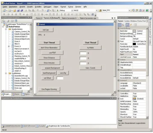
Visual Studio is an integrated development environment designed by Microsoft. It includes several tools that help in programming, like IntelliSense – an autocompletion tool for symbol names – and a form designer tool for building graphical user interfaces (GUIs – see Figure 15).
3. Hard- and software Master Thesis Björn Ostermann page 30 of 126
While Visual Studio supports many languages, the actual program developed in this project only used the C++ environment. Thus it was possible, to implement the program in the 2008 Express Edition, which is freeware.
Figure 15: MS Visual Studio form designer
3.5
Robot remote control language
The REIS robot’s control software is equipped with an extended markup language (XML) interface [75]. This interface can be used to remotely control REIS robots via a TCP/IP connection. The language used to communicate is RSV COMMAND XML, a language designed by REIS. A complete listing of all used commands can be found in Appendix I.
The usage of this mode of control is not the intended use of the robot in industrial environments. To prevent any PC connected to the robot from controlling it, this mode of operation is disallowed by default. Two conditions have to be met in order to be able to control the robot with a chosen PC. Firstly the XML support of the robot has to be explicitly allowed in the control software and set to a specific IP address. Afterwards any device with that IP can establish a socket connection via TCP/IP to the robot’s webserver (see chapter 3.6) and use this socket connection to transfer XML commands and receive their appropriate responses.
Secondly the robot will only execute XML movement orders from a PC, if the robot is set to “External Mode”. This mode can be set by a program running on the robot’s PLC, or by the usage of the robot’s control panel.
3. Hard- and software Master Thesis Björn Ostermann page 31 of 126
The XML commands are sent as arrays of characters. They start with <RSVCMD> and end with </RSVCMD>. Each command has a client stamp, a number that can be freely chosen and that can be used to assign responses to their respective commands.
The different commands are separated into three different application programming interfaces (API), the transformation API, the symbol API and the API for the program memory.
- The transform API consists of commands used to convert coordinates into the different coordinate systems. It contains functions for the calculation of the forward and inverse kinematics, described in chapter 3.1.
- The symbol API is used to read and write values into variables. These variables can be used to control the robot’s movement.
- The third API includes the commands necessary to read and write programs in the robot’s PLC’s memory.
In this project, only the second API, the symbol API, was used, since all necessary data of the robot are stored in global variables, which can be accessed and changed using the symbol API [76].
3.6
Control hierarchy
There are two control hierarchies to be considered in this project.
The first is the connection between the PC and the camera, which is provided via the universal serial bus (USB), both to send requests as well as to receive responses (see Figure 16).
PC USB
Figure 16: Control hierarchy between PC and Camera
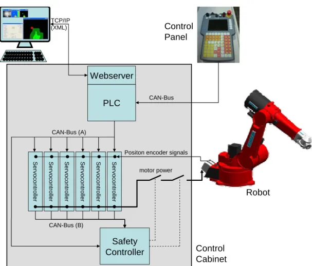
The second, more complex, hierarchy involves the PC, the robot’s control panel, the robot’s control cabinet and the robot itself. The complete hierarchy, created with information taken from a presentation [56] and email correspondence, both by/with Franz Som, Manager Control Development Software – REIS Robotics, is depicted in Figure 17.
The communication interface for an external PC is handled by a webserver of a programmable logic controller (PLC). This interface is used by the developed program, described in chapter 5. The connection to the webserver is handled via TCP/IP and the commands are sent as XML.
A control panel is directly connected to the PLC with the command transfer handled by a CAN bus. For safety reasons, as described in chapter 3.3 and 3.5, the panel is needed to start the “external mode”
3. Hard- and software Master Thesis Björn Ostermann page 32 of 126
of the robot. Afterwards it is continually needed to act as a hold to run button, while the robot is remotely controlled by the PC.
CAN busses are also used to connect the PLC to the servo controllers and the Safety Controller, which is charged with monitoring the correct execution of the position commands, as well as other safety related features. PLC Webserver PC S e rv oc on tro lle r S e rv oc on tro lle r S e rv oc on tro lle r S e rv oc on tro lle r S e rv oc o ntrol ler S e rv oc o ntrol ler TCP/IP (XML) CAN-Bus (A) Safety Controller CAN-Bus (B) CAN-Bus motor power Positon encoder signals
Control Panel
Robot
Control Cabinet
Figure 17: Control hierarchy from PC to robot – diagram created with the help of F. Som, REIS Robotics
If the safety controller detects an error in the execution of a command, it safely and redundantly cuts the power to the robot’s motors, causing the motor’s brakes to activate.
Direct communication between the safety controller and the PC is not possible. Thus any errors in the communication of PC and webserver can not be recognized by the safety controller. In a later industrial implementation, the safety controller would have to be included in the process of object avoidance, as described in chapter 7.2.
4. Overall evading concept Master Thesis Björn Ostermann page 33 of 126
4
Overall evading concept
In this chapter an overview of the developed concept for evading dynamic objects is presented. The overall task is the acquisition of data from the sensors, the calculation of a collision free path for the robot and its execution.
This overview focuses on the interactions of the single components of the workplace and their interfaces. The different subprograms and algorithms themselves therefore are explained only briefly in this chapter. A detailed explanation of the internal mechanics of the single algorithms can be found in chapter 5. At this point, these detailed explanations are not necessary for the understanding of the overall concept, but rather disturbing to the fluency of reading. They are meant for the detailed study of the developed program.
4.1
Tasks hierarchy
The task of this project is a safety system. Safety systems need to be able to operate in real time, e.g. their lowest possible response time must be at least as fast as the task demands. Therefore the execution time of the developed program needs to be as fast as possible. It has to be considered that image processing and path planning are tasks that require a relatively large amount of computational effort.
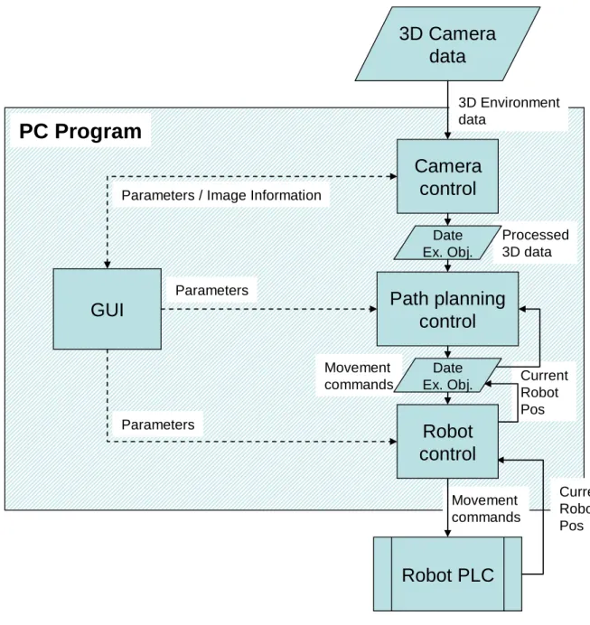
Modern PCs are equipped with multicore CPUs that allow parallel processing of different tasks, if those tasks are separated in the executed program in different threads. To use this advantage, the developed PC-program has been divided into four separate tasks, organized in separate kernel threads. In the used PC, a dual core processor was installed. By separation of the program into different threads the operating system has the possibility of allocating the threads to different CPUs, to better balance the computational load. This optimizes the execution time and contributes to the real time ability of the program.
The tasks are divided into the following threads: - Graphical User Interface (GUI) (chapter 4.2)
- camera control (chapter 4.3)
- path planning control (chapter 4.4)
- robot control (chapter 4.5)
4. Overall evading concept Master Thesis Björn Ostermann page 34 of 126
GUI
Camera
control
Path planning
control
3D Camera
data
Robot PLC
PC Program
3D Environment data Processed 3D data Movement commands Movement commands Current Robot Pos Current Robot PosRobot
control
ParametersParameters / Image Information
Parameters
Date Ex. Obj.
Date Ex. Obj.
Figure 18: Data exchange diagram
While the GUI and the robot control thread contain only few computations, the camera control and path planning control thread share the main computational load.
Each thread contains a setup phase, in which important variables are initialized, and a continuous processing loop, in which the computations are achieved. During this continuous loop certain variables are checked to switch sub-parts on and off (see following chapters). The values of those variables can be changed by the user using the GUI shown in Figure 19.
Exchanging information in variables accessed by different parallel tasks leads to consistency problems in those variables. To allow the safe data exchanged between the tasks, a data exchange object was created. This object handles the problem of dual access to single variables as well as the storage and retrieval of data from files (see chapter 4.6).
4. Overall evading concept Master Thesis Björn Ostermann page 35 of 126
4.2
Graphical User Interface (GUI)
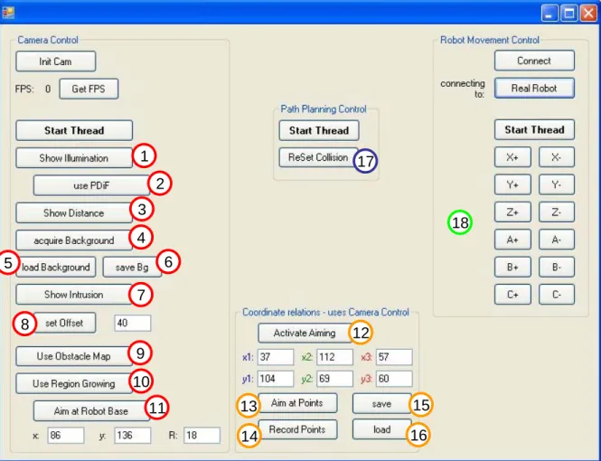
The GUI, handled by the main thread, allows the separate control of all threads involved (see Figure 19). At this stage of the development of this work a main switch, allowing every part of the program to be started simultaneously, was not programmed. The separate controls were necessary for a better control of the whole program during this testing phase. The GUI therefore is divided into four regions:
- Camera Control - Coordinate relations - Path Planning Control - Robot Movement Control
1 2 3 4 5 6 7 8 9 10 11 12 13 14 15 16 17 18
Figure 19: Main control window numbering in accordance with chapter 4.3 ff.
It has to be noted (see chapter 4.1) that even if the control of the threads is separated in the GUI for testing purposes, they work together automatically, if all threads are started.
In the region “Camera Control” the connection to the camera can be established, respectively disconnected if it was already established. Also the camera control thread is handled here, allowing the single sub-programs of the camera control thread to be switched on and off.
4. Overall evading concept Master Thesis Björn Ostermann page 36 of 126
In the region “Coordinate relations” additional controls for the camera thread are collected. They are only used during setup phase, if the camera’s position in the workspace has been changed (see chapter 3.3).
In the region “Path Planning Control” the path planning control thread is started / stopped. An additional function is to allow the user to reset the collision detection (see chapter 5.3), such that the robot can be allowed to continue working after an automatic stop induced by a collision.
In the region “Robot Movement Control” the connection between robot and PC-program is established, respectively disconnected. Also the robot control thread is controlled here, allowing among other things to manually change the robot’s position.
The single threads are described more precisely in the following chapters.
During the setup phases when the connection to the camera or to the robot is established, the GUI window blocks further user access to all its functions. This is due to the fact that the GUI thread handles those connections itself and does not delegate it to other threads. As described in previous work [78], the connection to the robot takes some time, depending on the responding hardware (robot or robot simulating PC).
Apart from those connection phases, the user can stop every thread separately at all times via the GUI. Threads are closed by the GUI using the transmission of a “thread stop” exception. This allows the user to stop the threads at every point during their execution, even if they are caught in a continuous loop.
4.3
Camera control thread
As described in chapter 3.6, the camera is connected to the PC via USB. The functions used to communicate with the camera are supplied by the manufacturer [55].
The camera controlling task handles the interpretation and display of the acquired images: - Histogram equalization of the intensity image (algorithm see chapter 5.1.1)
- Display of the intensity image (see Figure 21a)
- Depth to colour conversion of the distance image (algorithm see chapter 5.1.2) - Display of the distance image (see Figure 21b)
It also handles the processing of the acquired data and the display of the computed results: - Acquisition of the workspace’s background (algorithm see chapter 5.2.1)
- Finding the intrusions in the distance image (algorithm see chapter 5.2.2) - Displaying intrusions (see Figure 24)
4. Overall evading concept Master Thesis Björn Ostermann page 37 of 126
- Region extraction (algorithm see chapter 5.2.4.1) and identification from the found intrusions (algorithm see chapter 5.2.4.3)
- Computation of the distance between robot and other regions (algorithm see chapter 5.4) - Display of this distance (see Figure 27a)
- Computation of the space that can be reached by the robot (algorithm see chapter 5.5.3) - Display of this space (see Figure 27b)
Since the computations and presentations of the results require a certain amount of processor time, each part of the processing loop can be switched on and off by the user using the GUI (see Figure 19). This allows for single testing of the routines as well as an optimized working process.
For better clarity, the flowchart of the continuous loop of the thread is split into Figure 20, Figure 22, Figure 23, Figure 25, Figure 28 and Figure 30. The numbers and their colours in the flowcharts are in accordance with the numbering of the GUI in Figure 19. Each numbered button of the GUI controls one subpart of the camera control thread loop.
4.3.1
Intensity and distance depiction
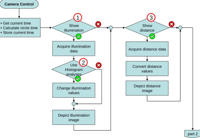
Figure 20 contains the first part of the continuous loop.
Camera Control
• Get current time • Calculate circle time • Store current time
Show illumination Acquire illumination data Use Histogram analyses Change illumination values Depict illumination image Show distance
Acquire distance data
Depict distance image Convert distance values part 2
1
2
3
Figure 20: Camera control thread – part 1 Timer, intensity and distance depiction