Real-Time Database Management Support in
a Component Framework
Ahsan Jawed and Kazim Sardar Mehdi
The Department of Computer Science and Electronics
Mälardalen University, Västerås, Sweden
Supervisors: Dag Nyström & Mikael Åkerholm
Examiner: Christer Norström
“Smart data structures and dumb code work a lot better than the
other way around.”
(Eric Raymond)
Abstract
The rising need of introducing a database in real-time embedded systems to handle increasing amount of data has given birth to several databases for embedded applications. But very little attention has been given to real-time embedded systems particularly the vehicular systems. Modern vehicular systems are also loaded with huge amount of data every year therefore a real-time database management system for vehicular system was created to address the problem. Similarly, a component technology was developed to help create an efficient and easy to maintain vehicular system.
This thesis focuses on integrating the real-time database management into the component technology for vehicular systems. From our findings, data-centric approach has been found best for integration process. Therefore, Introducing real-time database management support into component technology using data-centric approach is the main goal of this thesis. In the end as a result a complete framework is proposed that uses information-centric approach to show how a real-time database management system could work with component technology to design vehicle-control systems in particular.
Preface
During this Master thesis project we have encountered problems that couldn’t be solved without the help of our supervisors Dag Nyström & Mikael Åkerholm. We are thankful to them for their support and help throughout the thesis. Furthermore, we would like to thank Volvo Construction Equipment AB for going through our research work and giving feed back. They have been a great source of encouragement for us to continue with our research work.
Table of Contents
1. Introduction……….7
1.1.Introduction to COMET……….8
1.2.Introduction to SAVE……….9
1.3.Overview of Problem………..9
1.4.Why a Data-Centric Approach Streamlines Embedded Software Development?..9
1.5.Thesis Outline………...10
2. Background………12
2.1.Component Framework………12
2.1.1. Component……….12
2.1.2. Framework……….12
2.1.3. Component-based Software Engineering ……….13
2.2.Database Management System……….14
2.3.Real-Time Systems………...15
2.4.Real-Time Database Management System………...15
2.5.Embedded Systems………...15
2.6.Vehicle Control System………16
3. Related Work……….18
3.1.ENCIRQ Data Foundation Framework………18
3.2.The Evolution of Data-Centric Development………...20
4. COMET………..22
4.1.COMET Database Management System……….22
4.1.1. COMET Key Concepts……….22
4.1.2. Database Pointers………..24
4.2.COMET BaseLine Overview………...25
4.3.COMET MiniLine Overview………...27
5. SAVECCT………..29
5.1.The SAVE Project ………...29
5.2.AutoComp Technology………29
5.3.SAVEComp Component Model………..30
5.3.1. Architectural Elements………..30
5.3.2. Specification & Composition Language………...32
5.3.3. Graphical language………...34
6. Problem Formulation & Research Methodology………35
6.1.Methodology……….35
6.2.Problem Definition………...37
6.3.Research Questions………..38
7. Data-Centric Based Framework Proposal……….49
7.1.Generator……….49
7.1.1. Component Generator………...49
7.1.2. Database queries and relation Generator………..51
7.2.Repositories………...53
7.2.1. Data Flow from and to Repository………....54
7.3.Roles………55
7.4.Architecture tool/Information centric viewer (ICV)………56
8. Example using theData-Centric Based Framework……….58
8.1.Development Process……….58
8.1.1. V-process Model……….58
8.1.2. Example using the Process Model………..58
Chapter 1
Introduction
Day-by-day millions of systems running on this planet are getting enriched with tones of information that is being used to achieve goals and produce efficient outputs. This fact is also true for vehicle control systems that are facing problems in handling huge amount of data with limited resources. This problem has been addressed within the COMET project [1-1] that proposes a real-time database management system that could be integrated into vehicle control systems. On the contrary, to enhance the efficiency of embedded control systems in vehicles a suitable component technology has been proposed within the SAVE project [1-2], using the benefits of component-based software engineering (CBSE).
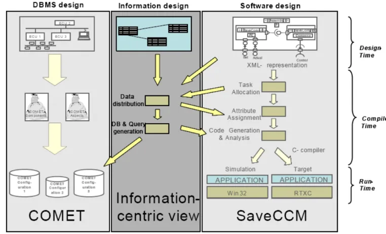
In this thesis the best use of the above proposed solutions within their respective projects could only be achieved when they both work together for vehicle control systems. Therefore, the idea is to integrate the real-time database management system (RTDBMS) proposed by COMET project and the SaveCCT proposed by SAVE project using an information-centric view approach as illustrated in Figure 1.1
The above figure has been taken from the thesis proposal document that has three major parts showing COMET on the left side, SaveCCT on the right side and the information-centric view in the middle as the integrating part. The COMET & SaveCCT parts illustrate the basic steps to generate the database and the target application respectively. Whereas, the information-centric view is the area where the information from both the systems is gathered and exchanged to incorporate compatibility for each other. The arrows represent the direction of information flow to and from the information-centric view. Information like XML representation of the component design & database schema and task allocation flows into the data distribution unit of information-centric view. Once the data is collected it is distributed for database generation, Attribute assignment and code generation. This distribution of data is shown by the out going arrows from the information-centric view to the left and right side parts of figure 1.1
This thesis focuses on the integration of a real-time database management with a component framework for vehicle control systems. Currently, there is no connection or communication between COMET and SaveCCT. Results of this thesis would be a component technology with the support of real-time database that will include a bridge between the two systems and make them capable to run for any vehicle control system. In order to understand this thesis, overview of COMET and SaveCCT are included that will highlight their individual requirements for vehicle control systems.
1.1
Introduction to COMET
COMET is a research project distributed between two Swedish Unversities, namely Real-Time Systems Laboratory at Linköping University, and Mälardalen Real-time Research Center at Mälardalen University. The aim of the project is to develop techniques for design and development of real-time embedded databases. Furthermore, they also intend to enhance the functionality of existing databases that work in real-time and embedded environment. The new software engineering techiques for design of real-time systems and novel database mechansims are applied on an experimental real-time embedded database platform called COMET (a component-based embedded real-time database system). [1-3]
COMET now includes couple of versions like COMET BaseLine and COMET MiniLine that were developed to focus systems with specific set of requirements. COMET BaseLine includes all basic features of a database management system with respect to the requirements of a real-time embedded system, thus making it a RTDBMS (Real-time Database Management System). COMET MiniLine was developed to fit into a vehicle control system with limited resources, therefore it includes only few necessary features of a database management system.
In short, COMET aimed to develop a real-time database management system that could be supported by a component framework also developed for real-time embedded systems. The reason for using component framework and a database management system for real-time embedded systems such as vehicle control system was to reduce the increasing
complexity of embedded real-time systems as well as to manage the increasing amount of information that increments 7 – 10 % every year[1-4].
More detailed information on COMET is included in chapter 4 to get complete and good understanding of this thesis.
1.2
Introduction to SaveCCM
SaveCCM is a component model designed under SAVE project that is running in Malardalen Real-time Research Centre of Malardalen University. The aim of the project is to create a Component technology for safety-critical real-time embedded systems. It also intends to device a systematic procedure for developing component-based software for safety critical embedded systems. The design and analysis of the component based architecture with respect to safety and real-time context would be a huge project keeping in mind the varieties of present real-time systems. Therefore, the focus is directed to only single application area for vehicular systems to reduce the overall project complexity to a manageable level [l-5, 1-6].
SaveCCM is the component model that is designed for real-time embedded systems keeping in mind to incorporate the support for Real-time Database Management system. Obviously, it includes all fundamental parts a component framework should have beside some additional features that were required to adjust the real-time requirements. SaveCCM has defined its own symbols and connectors to represent components and communication between components. Further details on SaveCCM can be found in chapter 5 to deeply understand the model and make this thesis easier to understand.
1.3
Problem Overview
We now have a real-time database management system for embedded systems as well as a component model for real-time safety critical systems; therefore it is worth to integrate them to address the data management issues of the modern vehicular systems. Once the integration has to be done the study required to investigate this integration, determine its requirements and find out the approach best appropriate will be covered in this thesis. At the moment data-centric approach to connect the systems is found interesting, further motivation f which could be found in next section.
1.4
Why a Data-Centric Approach Streamlines Embedded Software
Development?
There are lots of areas where data centric approach proves best approach. Some of them are discussed here.
1. Reduced Complexity Through Data Abstraction
By creating data abstraction layer over the data gives easy access to the data. That is much easier for the developer to understand and easier to use. Data management in
data centric applications is by using PL/SQL like programming construct that is not strange for the developer. This kind of programming construct hides all the complexities from the eyes of the developer in accessing the data.
2. Faster, Easier Development
By using the Data centric approach in the development of the application, it reduces the overall development time of the application. The developer not needed to design data access method by it self that reduce the overall application development time. 3. Easier and Better Optimization of System Resources
By designing the data model using PL/SQL like programming construct the data schema is compiled by using the compiler. That produces the code which is well optimized and utilizing the resources at the maximum. This is done because the compiler is designed in viewing the whole hardware architecture of the target machine.
4. Higher Software Quality
By using the data centric approach in the development increase the overall quality of the software. Because the amount of code decreased, complexity of the code also decreased. Automation of the code also helps in reducing the debugging time.
5. Higher Data Integrity and Reliability
In today’s devices data integrity is became a need. The amount of traffic is increasing between the device and the central station. To handle this transaction processing is required which is not an easy task to design. But by using data centric approach all is available in a bundle that provides all the required services to manage.
6. Increased Application Portability
Application portability is the mere dream because developing portable code for an environment that has very limited resources and processing is very hard job. But by using data centric approach the portability of the code is increased. As the code generated by the system can be downloaded to any kind of target.
7. Increased Flexibility
By using data abstraction from the program logic it helps in increasing the flexibility in both sides. It is easier to replace the program logic or introduce the new data model to the device without disturbing the other one.
1.5 Thesis
Outline
The thesis is divided into three major parts: Part I (Thesis Introduction & Background)
Chapter 2 – Background Chapter 3 – Related Work Chapter 4 – COMET
Chapter 5 – SAVE
Part II (Thesis Study & Contribution)
Chapter 6 – Problem Formulation & Research Methodology Chapter 7 – Data-Centric Based Framework
Chapter 8 – Example using the Data-Centric Based Framework Part III (Thesis Conclusion & Result)
Chapter 2
Background
2.1 Component
Frameworks
2.1.1 Component
The term Component in computer world is introduced by Peter Jones [2-1-1]. And he was also first one who distinguishes between component and object. The most basic difference is components are evolved by composition where as objects are by inherence. “A Software component is a unit of composition with contractually specified interfaces and explicit context dependencies only. A software component can be deployed independently and is subject to composition by third party”. [2-1]
Components have well defined interfaces that show what these component present to the world. As we already mentioned that component evolves through composition that means just by changing the arrangement of the components we are able to design new software. Software components are designed to be used as a plug and playable. But in reality they are not able to provide this functionality because not all components have compatibility with each other. Components need a platform on which they can stand and able to work together that platform is known as Component Framework.
2.1.2 Framework
A framework is not the actual operating system; it is a platform which is meant to provide a standard ground components. That framework includes number of services specific to a component technology. While frameworks in general describe a typical and reusable situation at a model level, a component framework describes a “circuit-board” with empty slots into which components can be inserted to create a working instance. [2-2] Frameworkin general is taken as a circuit board or Lego base board where different other pieces can be placed to make it functional. Framework can be seen as an operating system providing services for maintaining all the operations and functionality among components. In specific to computer, it is a platform that provides the services and tools that required putting different type of component together by using a glue code.
There are lots of examples of component frameworks are available, you can say Internet explorer as a framework and the plug-in are the components. “Microsoft.net Framework” also an example of framework.
Advantages of using Component Framework: • Increase productivity
• Decrease the product development life time • Decrease the product cost
Component Models:
Component models are the well defined methods and practices of industry for the construction of the component based software. To design a component based software we need to stick with one specific platform. Most common component models are:
• Open Architecture CORBA • Sun’s Java Beans
• Microsoft’s COM, ActiveX and .net Framework 2.1.3 Component Based Software Engineering
Traditional software engineering is not coping with new development techniques of Component based Software engineering. Component Based Software Engineering is now considering as a major part of current software engineering. The major goals of Component based software engineering are [2-3]
• To provide support for the development of system as assemblies of components; • To support the development of components as reusable entries;
• To facilitate the maintenance and upgrading of system by customizing and replacing their components.
Component based software engineering is in developing phase, but it already accepted as a powerful solution to the development of softwares. By using component based software engineering it will be much simple the whole software development lifecycle. Component based software engineering also doing the standardizing the development of applications either by using in-house developed components or by purchasing components from the third party. Component based application also made easier the process of application up gradation, by just replacing the component and the application is updated now.
In fig # 2.1 boxes are representing components, underlying platform represent the framework and the whole picture is the representation of the component based software engineering. This figure is presenting the whole picture of components and interaction with each other and framework is underlying of everything and this whole process is come under component based software engineering.
2.2
Database Management System
Database is a collection of record stored in a computer in a systematic order. That is being accessed by the program to answer the queries put by the user. Database can be seen hierarchy of arrangement of data i.e. smallest is field then collection of field form shape of a record ,then collection of record took the shape of the table and multiple tables related of each other grouped and then that group known as Database . Start from the filed and collection of field form a shape of a record and collection of record form a shape of table and collection of tables known as database.
Database Management System (DBMS) is a collection of programs that are use to store, retrieve and manage a database. There are number of database management system are available ranging from personal use to enterprise level. [2-4]. DBMS is mainly divided into two types. File base DBMS and system level.
Examples of file bases DBMS is Microsoft Access and system based are oracle or Microsoft SQL SERVER are the most common. Each DBMS much provide DML (Data manipulation Language) and DDL (Data Definition Language) for working. All the DBMS system incorporates all the ANSI standard SQL (Structured Query Language) constructs. And most of them enhanced them to a more extended level like Oracle provide a super set of SQL known as PL/SQL having much more power then the standard SQL provide.
Problems of Using Flat File for data storage:
1. Data from flat file can only be accessed sequentially.
2. File can be accessed by one user at a time. If it opens in sharing mode then data consistence is compromised.
3. Restricting access to the simple file is not an easy job.
Advantages of Using DBMS:
1. Redundancies and inconsistencies can be reduced
Due to centralized data management store, data redundancies will be reduced as well as data inconsistency also reduced. Because all the stored data managed by one manager that is DBMS and all data is stored in one place.
2. Better service to the user
User who need to access the data are much freer to access data in any order they prefer. Combining different types of data is easily managed if it compared with the traditional filing system.
Standardization of the data can be done easily as all data is maintained in one place. DBMS provide different ways to apply different constraints and rules on the data management.
4. Increase Security of Data
DBMS provide rule base security model to handle user rights on the data stored inside the database. By restricting the operations one can apply on the data.
2.3 Real
time
System
In the most simple words Real time system can be defined as Systems that can produce correct output at the correct time, the system which satisfied these two qualities are called a real time system.
Complete Definition of real time system is:
“A real-time system is a system that reacts upon outside events and performs a function based on these and gives a response within a certain time. Correctness of the function does not only depend on correctness of the result, but also the timeliness of it”. [2.5]
There are two types of real time systems. 1. Hard Real time systems
2. Soft Real time system
Hard Real time systems: In these category most of the system are safety critical system that have no chance to miss any deadline or give wrong output. It includes Nuclear power plants, Patient care systems, system working in airplanes.
Soft Real time Systems: these are systems allowed to miss deadline because they are not safety critical system. It includes Video processing system, Window control system in vehicles.
2.4
Real time Database Management System
Real time Database Management System as name suggest it is a database system that should provide basic database Management operation that includes queries
processing, transaction control ,concurrency control and commit-protocol. With that the most important it should produce the correct output that also satisfies the time requirement. [2.4.1]
2.5
Embedded System
The special purpose system that includes a computer which is completely encapsulated by the device is known as embedded system. These systems have very limited resources and less computation power. They are not general purpose machine.
They are designed for some specific operations. Mostly embedded systems have real time operating system in it.
Here are some examples of embedded system. Examples of embedded systems 2.5.1] • automatic teller machines (ATMs)
• avionics, such as inertial guidance systems, flight control hardware/software and other integrated systems in aircraft and missiles
• cellular telephones and telephone switches
• computer network equipment, including routers, timeservers and firewalls • computer printers
• copiers
• disk drives (floppy disk drives and hard disk drives)
• engine controllers and antilock brake controllers for automobiles
• home automation products, like thermostats, air conditioners, sprinklers, and security monitoring systems
• handheld calculators
• household appliances, including microwave ovens, washing machines, television sets, DVD players/recorders
• medical equipment
• measurement equipment such as digital storage oscilloscopes, logic analyzers, and spectrum analyzers
• multifunction wristwatches
• multimedia appliances: Internet radio receivers, TV set top boxes, digital satellite receivers
• Multifunctional printers (MFPs)
• personal digital assistants (PDAs), that is, small handheld computers with PIMs and other applications
• mobile phones with additional capabilities, for example, mobile digital assistants with cell phone and PDA and Java (MIDP)
• programmable logic controllers (PLCs) for industrial automation and monitoring • stationary videogame consoles and handheld game consoles
• wearable computer
2.6
Vehicle Control System
The functionality of today’s modern car is mostly controlled by the computer based system that system is known as vehicle control system. Vehicle control system control large number of functionality of car ranging from safety critical that includes engine control, transmission control to diagnostics and providing additional facilities to the driver that includes Global Positioning, climate control and multimedia services inside the car.
Generally vehicle control system consists of number of computer nodes that are connected through CAN (Control Area Network) protocol. Vehicle Control System is constantly managing the activities in the vehicle so it should support real time properties. Vehicle control system provide both hard as well as soft real time services as per needed by the application. [2-6]
Chapter 3
Related Work
In this section we are trying to present some of the work which already has been done to address the problem of handling data in embedded devices more efficiently.
3.1
ENCIRQ® DATA FOUNDATIONTM FRAMEWORK v2.0
This is a complete suite of tools and technologies required to design and implement data centric application for embedded devices. This Software framework is designed to address the problems facing by the software industry in developing software that requires data management but having very small resources. [3-1]
The major problems faced by the developer of embedded devices are: 1. Handling Data efficiently is a requirement
2. Languages (C, C++, and Java) not designed for managing data. 3. Slow development processes.
Handling Data efficiently is a Requirement:
Embedded devices in start are based heavily dependant on software. They are solely dependent on the programming logic and require very small amount memory to handle data. But as time passed requirement changes very fast, and the data flow increased. To handle this requirement data management technique is needed which is not available in the software development cycle.
Languages (C, C++, and Java) not designed for managing data.
All high level languages are designed to streamline the software development not the data management process. SQL is designed to handle data management efficiently and uniformly regardless of the provider and data management system. And have easy interaction with programming environment.
Slow Development Process:
If the developer try to design some data management handler by himself then it will be very time consuming task and it provide very limited functionality and reusability. And slow down the whole process of the development.
To address all these problems ENCIRQ came up to the origin of software development. ENCIRQ Corporation claims that it is the first of its kind. This framework includes a PL/SQL like database operation engine, components and runtime library for the target device.
There are two main parts of the framework. • Development framework
• Runtime Environment Development Framework:
Development framework includes lots of components that are essential for the development of the software that evolve around the data.
• ENCIRQ PL • ENCIRQ Prototyper • ENCIRQ Generator ENCIRQ PL:
This is the extended version of the standard SQL. With the most optimized ENCIRQ PL language that is designed to suite the requirement of the embedded devices.
ENCIRQ Prototyper
It is a prototype designer tool use to efficiently design, implement test and debug the data logic in an easy operative environment.
ENCIRQ Generator:
This is main compiler of the systems that converts the data logic designed using ENCIRQ PL language into the optimized ANSI C functions that then be build delivered to the target device.
Runtime Environment:
It includes the service libraries needed by the code, generated by the ENCIRQ Generator. These runtime libraries occupies very small amount of memory i.e. around 35 kb only. These libraries include:
• Memory and storage management services • Indexing services of accessing data more rapidly • Transaction handling services
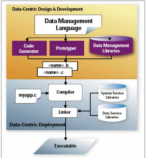
Figure 3.1 The visualize representation of the ENCIRQ development process
The figure 3.1 represents the software development lifecycle using ENCIRQ framework. In the first step the developer develop database scheme by using ENCIRQ PL. that database scheme then given to the second phase where the code generator generate the code , it generate ANSI C code that can be complied using specific compilers to generate the device dependant code for the target device.
3.2 The Evolution of Data-Centric Development
Problems Faced By the Software Industry:
As the prediction stated that by the year 2010 most of the devices compromises of software. These changes in the development of products increase the responsibility of the software developers. They have to design software that required fewer amounts of computation as well as not resource hungry.
These are the main problems faced by the software developers.
• Hardware selection without much effort in seeing the impact on requirement of software.
• In fulfilling the requirement of the everyday customer companies have to upgrade the hardware very rapidly. That gives great pain and time to the software
developer to port the code to the new target.
• Frequent change in the software and porting to the new hardware left the developer with less time to learn new software development processes and etc. • Industry is lacking of the production houses that are designing off the shelf
products that can be plugged into the development of the software cycle. There are number of lesson learned by the software industry to cope with real world problems that are faced during its evolution. Some of them that address our problem stated here.
Lesson 1: Standalone system to the data centric application
The start of the software industry is with the mainframe computers that are used to solve specific business problem. As the code increases the shape of the code is similar to the spaghetti in a plate. That time no one is thinking of developing software with the thought it can be used in solving other problems also.
Then there comes the age of distributed systems where software is divided into different computers. Then the data management techniques are used to manage the data between the different nodes.
Data abstraction layer is introduced to create interoperability and reusability of the designed components. That reduces the development cost and centralizing the data. That results in easy to manage as well as easy to port data.
Lesson 2: Automate the software development
To increase the software development processes the automation techniques are introduced in the software development. Just by specifying some of the setting, the wizard will do the rest of the work. For instance like design the whole data model in using interface like the Oracle’s PL/SQL. And then forward the scheme to the compiling engine that generates the target specific functions.
Lesson 3: Usage of Higher Lever Development Environment
The software developed using higher level language take lesser time as compare to develop the similar nature software using lower level of language. Designing data oriented application using SQL like interface create a lot difference in the development time if we compare it the home-made data management handlers.
Lesson 4: Common Infrastructure for Interoperability
Every where in the computer world application are divided into categories. For instance spreadsheet applications, word processing application and common constructs in programming languages.
In the same way common infrastructure builds to facilitate this universality between devices development. Like basic framework designed by some other vender and application that executed on the framework is by different vendor. By creating a centralize data management any vender’s specific code can have access to the code.
Chapter 4
COMET
In order to give the reader a better understanding of the COMET project, this chapter talks about the COMET system and its architecture. It also provides some brief information about its implementations: COMET BaseLine & MiniLine.
4.1
COMET Database Management System
COMET is a project that aims to develop a real-time database management system for embedded systems, specifically the vehicle-control system. Therefore, COMET stands for COMponent-based Embedded real-Time database management system. Creating database for embedded systems focuses the problem of managing the increasing data volume in automotive systems that is predicted to increase 7-10 % every year [4-1]. This section includes the key concepts of COMET database, the platform it uses and a configuration example to finish with.
4.1.1 COMET Key Concepts
Using the component-based software development paradigm databases can be partially or completely assembled from pre-defined and well interfaced components. These components are also helpful in tailoring database systems into an application. Therefore, various aspects of database are encapsulated into components to enable efficient development of configurable RTDBMS. In COMET aspectual component-based real-time system development (ACCORD) [4-2] has been used to develop its architecture that comprises of the following components:
• The user interface management component – It is responsible to provide interface to the applications and processes running outside the database. Applications like those which users can use to make ad-hoc SQL Queries to the database. It provides operations like making new transactions, COMMIT & ROLLBACK operations and make SQL Queries. In addition to the query processing and user interactions COMET is also responsible for maintaining list of active transaction.
• The Transaction management component – This component is created for executing the execution plans passed from user interface management. It can log all transactions to ensure recoverability and serialization. In order to execute a transaction plan and to make sure the system follows the ACID properties, TMC communicates with other components of DBMS [4-3].
• The Index management component – indexes are used to fetch data from the database as quickly possible. Whenever a value is requested the component fetches an ordered list of keys that is related to the requested data. Then the
memory address associated to the key is used to actually access the data from database.
• The memory management component – this component is mainly responsible for the physical memory management. It allocates memory when new data tuples, metadata and indexes are added.
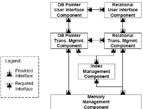
These above described components combine together to form the basic COMET architecture that aims to provide configurability so that it could be easily handled for variety of application requirements. Figure 4.1 shows the basic architecture of COMET that is fully instantiated to refer as the basic configuration. The basic configuration builds a fully functional RTDBMS that is capable of storing, manipulating and querying data. Beside, this configuration is not capable of handling concurrent transactions and has no database crash recovery mechanism [4-4].
Figure 4.1 The basic architecture of COMET [4-4]
The COMET development suit or platform includes components and aspects that work together to produce different configurations for different requirements. Aspects are programming-language level constructs encapsulating crosscutting concerns that invasively change the code of the component and correspond to the traditional aspects in existing aspect languages. The main constituents of aspects are: (i) components, written in a component language, e.g., C, C++, and Java; (ii) aspects, written in a corresponding aspect language, e.g., AspectC [4-5].
4.1.2 Database Pointers
Database pointers allow the system to access individual data elements within the database using an efficient and predictable way. The purpose of database pointers is directly related to the real-time properties of the database. The hard tasks of COMET database are handled using database pointers to ensure data searching and retrieving process be fast enough to meet the deadlines. For example, data related to the car acceleration or engine is very important that could be required by a hard task in the system. Therefore, such type of data access should neither be blocked nor locked for longer time. To reduce data locking time and increasing data accessing time database pointers are found most appropriate for real-time database management systems.
Focusing on the implementation side of database pointers, the concept is implemented using four different components namely: the DBPointer data type, a database pointer table, a databasepointer interface and a database pointer flag. The DBPointer data type is the actual pointer defined in the application. The database pointer table contains all information needed by the pointers. The database pointer interface provides a number of operations on the database pointer. The database pointer flag is used to ensure consistency in the database [4-6].
A request for a very important data, for example x is made that is to be accessed using database pointers would be accomplished by following steps:
• A read operation together with the database pointer that would be submitted to the database pointer interface.
• The database pointer, acting as an index to the database pointer table array would then be used to get the corresponding database pointer table entry. Each database pointer table entry consists of three fields: the physical address of data element x, information about the data type of x, and eventual locking information that shows which lock x belongs to.
• Next the lock would be obtained and x would be read.
• Finally, the lock would be released and the value of x would be returned to the calling application.
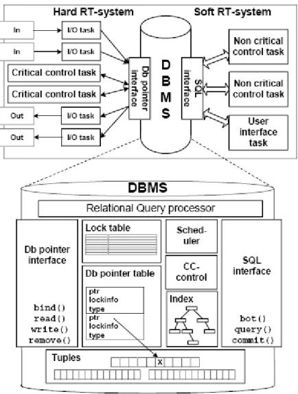
In [4-7], author very illustratively describes the architecture of COMET by the figure we have adopted as Figure 4.2. It shows the role of database pointers and how its components are related in COMET real-time database management system. The Database has two interfaces namely: DB Pointer interface and SQL interface. DB Pointer interface involves database pointers that are used by the hard real-time tasks to access the data directly from the database. The non-critical tasks or soft tasks use the SQL interface to access data. The figure further illustrates that DB Pointer interface is connected to the DB Pointer table that holds all the DB pointers and the memory addresses they are pointing to.
Figure 4.2 Architecture of a controlling system that uses a DBMS with database pointers.
4.2
COMET BaseLine Overview
COMET BaseLine is the first implementation of the COMET RTDBMS that is divided into two parts: the relational part and the database pointer part. The relational part is handling the soft real-time transactions whereas; the database pointer part handles the hard real-time transactions in the RTDBMS. Soft real-time transactions include ad-hoc queries and manipulation of database schema. Hard real-time transactions include data access to single elements that need to be executed deterministically. Both parts share the index and memory management components but have their own user-interface and transaction management components. The architecture of COMET BaseLine is illustrated in Figure 4.3
Figure 4.3 Architecture of COMET BaseLine
The Relational part of COMET is responsible for managing transactions and parsing SQL queries. The Relational User Interface Component (RUIC) is the first part that uses a parse tree to parse the SQL queries in order to turn them into execution plans. There are four APIs that can be used to access this component in order to manipulate data and database schema. Then the second part or relational part of database is Relational Transaction Management component (RTMC) that is responsible for executing the execution plans passed over by RUIC.
The Database Pointer part of COMET is mainly responsible for hard real-time transactions of the database. The Database Pointer User Interface Component (DPUIC) provides the database pointer interface to the applications that includes all basic operations an application can do using database pointers. The Database Pointer Transaction Management component (DPTMC) administers the list of database pointers and executes requests from DPUIC.
Index management in COMET BaseLine is implemented using two internal structures, a relational index and second is the tuple index. The relational index is statically bounded since the number of relations in BaseLine is fixed. All the tuples in a relation are linked together as a link list. This is implemented using the T-tree algorithm. The main advantage of using two separate internal structures is that it makes it possible to tailor the index structure after the dynamic behavior of the database [4-3].
The Memory manager of COMET BaseLine is responsible for allocation and de-allocating memory when a data or tuple is added or deleted. It provides interface that contains methods to allocate & de-allocate memory as well as read & write data or tuple.
4.3
COMET MiniLine Overview
COMET MiniLine is the implementation work done as a Master thesis under project COMET. There have been some new methods introduced for designing of database management system that are included in this section. It is important to mention that MiniLine targets small embedded systems like embedded on-board computer responsible for example car brakes. Therefore, MiniLine cannot afford to adopt all features of BaseLine as it uses significant amount of system resources at runtime and targets larger and more powerful electronic control units.
The main characteristics of MiniLine that are different from BaseLine are:
• All tasks of every node are known before runtime therefore no ad-hoc queries are required during execution.
• The number of data elements handled by a node is static i.e. number of tuples never change.
• The database schema is never changed.[4-3]
Due to the characteristics mentioned above the execution of the system could be divided into two parts: pre-runtime part and runtime part. Since the database schema is known in advance therefore, its creation and initialization could be performed before runtime. Queries are well defined before actual execution so MiniLine can manage to have pre-parsed or pre-compiled queries before runtime. Dynamic memory allocation is removed from the runtime part and replaced by static memory allocation. The pre-runtime part is incorporated into a tool that is referred to as offline tool.
Consequences of the new properties of MiniLine also include more predictability since the index lookup method is removed due to a static memory allocation and data fetching time has reduced considerably. This increase in predictability makes the job of calculating the worst-case execution time of tasks easier. Secondly, the design of database is moved to the pre-runtime part that gives more time for architect to make efficient decisions and produce better database schemas.
The intended execution of COMET MiniLine as mentioned in the previous Master thesis starts with the configuration file that includes database schema, database pointers and the queries. The configuration file will be taken as input by the offline tool called code generator tool that is responsible of producing three header files in C language. The first header file includes information about the database schema, second file contains information to initialize the database and the third file includes the functions that maps each query in configuration file. Then the kernel code with the header files is compiled by the C compiler to produce the executable MiniLine database management system. Figure 4.4 [4-3] explains the execution path of MiniLine.
Figure 4.4 the steps needed to create a working MiniLine system [4-3]
MiniLine System is implemented using C language therefore Structures that allows making user defined data-types in C language are used to define relations and tuples. This would result in data storage with minimum overhead that is most suitable for MiniLine system. There are basically, three structures (i) Database structure, (ii) Relation structure and (iii) Tuple structure as shown in figure 4.5 [4-3].
Chapter 5
SAVE
5.1
The SAVE project
SAVE project is running in Malardalen Real-time Research Centre of Malardalen University. The aim of the project is to create a Component technology for safety-critical real-time embedded systems. It also intends to device a systematic procedure for developing component-based software for safety critical embedded systems. The design and analysis of the component based architecture with respect to safety and real-time context would be a huge project keeping in mind the varieties of present real-time systems. Therefore, the focus is directed to only single application area for vehicular systems to reduce the overall project complexity to a manageable level [1-5, 1-6].
SAVE will address the problems of complex real-time systems by introducing a component technology that is best suitable for safety critical embedded systems like vehicle-control systems to make the best use of the advantages of a component-based development to reduce complexity and increase efficiency of real-time embedded vehicular systems.
5.2
AutoComp Technology
The component technology for safety critical real-time embedded system, described in [5-6], is developed considering the requirements of the vehicular system. The technology allows the engineers to involve in component based development without getting worried about the heavy run-time mechanisms. It mostly relies on the powerful design and compile-time mechanisms along with simple run-time methods. AutoComp technology has three parts: Component model, real-time model and run-time system model. The component model is what the architects can create during design time with full liberty of using component based software engineering techniques. The high level temporal constraints are also supported e.g. end-to-end deadlines and jitter calculations etc… so the designers don’t have to worry about assigning fake attributes to tasks.
Once the component model is designed it is transformed into a real-time model that provides exact high level temporal constraint values that are forwarded to the run-time model for accurate implementation. The real-time model also maps the component model on the real-time Operating system during compilation process. In compile time the main concerns are components replacement with tasks, task attributes assignment and real-time analysis. Also, the attributes of the underlying operating system are assigned to tasks so that the high level temporal constraints specified by the user are met. To meet the constraints of the system a synthesis process is activated that creates the executable target application by bundling the operating system, the run-time system and the application code into one. The above described technology is also represented in figure 5.1
Figure 5-1 The AutoComp Technology [5-6]
5.3
SAVE Comp Component Model
SAVE Comp Component Model (SaveCCM) and its predecessors is specifically designed keeping in mind that the model should be as restrictive as possible that could still allow easy application development. Since it is designed for the vehicular domain therefore, predictability and analyzability are more important than flexibility. SaveCCM has its root in previous models and design methods for embedded real-time systems like Basement [5-2] and its extensions into the Rubus-methodology [5-3] [5-4], which is currently in industry use.
5.3.1 Architectural Elements The main elements of SaveCCM are:
• Components – these are the basic units that contain attributes and behavior. These behavior and attributes work according to an execution plan defined in it. They also have interfaces that allow sending inputs, using the behaviors and receiving outputs.
• Switches – these allow to dynamically changing the component interconnection structure during runtime or configuration.
• Assemblies – these provide means to combine interconnected components with switches to form bigger components.
• Run-time Framework – It is responsible to provide services like communication between components, their execution and controlling sensors & actuators etc… Functional Interface
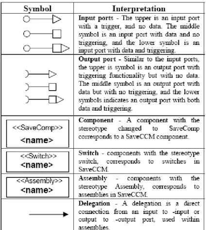
All elements of SaveCCM have set of functional interfaces that are defined in terms of ports. Ports are the communication points that every element uses to communicate with the outside world. There are two kinds of ports: input port and output port. Each kind of port can either transfer data or signal. But SaveCCM distinguishes three types of ports: (1) data-only ports, (2) triggering-only ports, and (3) data & triggering ports. Every input and output port can be of any types mentioned above. Ports can be connected only if their types and data-types match. For example, a data port that sends an integer data type can only be connected to a data port that receives an integer data type. Therefore, an output port is always connected to an input port.
Data-only ports are single data element buffers that can receive a data element or make it available on the port to be read. The write operation is always over writing the previous value in the buffer. The data made available on the output port is not instantly accessible to an input port since the communication is done on a network of several nodes.
Triggering-only ports are used to activate the components that may have one or many triggering ports. In that case when all the input triggering ports are active then only the component gets activated giving an “AND-semantics”. When all output triggering ports are connected to one input triggering port then this forms an “OR-semantics”. Activations of ports cannot be cancelled and activating an active port makes no sense.
Data-only and triggering-only ports combine to give a data & triggering port. Execution Model
Control-flow paradigm is found in the execution model of SaveCCM where the components execute due to clock triggering or external events triggering, and they have finite possibly variable, execution time. A component has two states: waiting and executing. The component is waiting until all its triggering ports are activated. Once that happens then the component immediately jumps to the executing state.
During execution, components go through three execution passes or phases. In the first execution phase all the inputs are read by the component. Then some computations related to the inputs only are performed in the second execution phase. And finally, the component generates output on to the ports. After the execution is over the component jumps back to the waiting state.
External I/O
Sensors and actuators are accessed through components that read some values from sensors though input ports and perform some computations to produce output. The output
could be generated for another component or for an actuator connected though output port.
Timing
Timing is controlled by components that are called triggers. They are assumed to be a perfect clock that can trigger other components to make them execute.
Switches
Switch is a selection pattern that helps decide the connection path between components depending on the data. In simple words, a switch is configuration of assemblies – set of interconnected components. It specifies a set of connection patterns that include connections from input ports to the output ports. Not necessarily all input ports should be connected to all output ports, but only the required ones. The connection pattern is selected depending on the data available on some of the input ports. Switches are also used for specifying modes in the system, like a switch could be statically configured to have few modes that could be selected just by changing a value on the input ports hence making a mode-switch.
Assemblies
As mentioned above assemblies are combination of components and switches that can have ports as every element of SaveCCM has. Some of the ports of components and switches can be dedicated as the external ports of the assembly. In SaveCCM, assemblies should only be viewed as a way to name a collection of components and switches and to hide the internal structure, rather than a mechanism of component composition.
Quality Attributes
SaveCCM maintains a list of quality attributes within specification of components and assemblies that are related to real-time and safety.
5.3.2 Specification & Composition Language
“Components are specified by their interfaces, behavior and (quality) attributes. Interfaces are port-based and they specify input and output ports. Behavior identifies variables that express internal states, and actions that describe the component execution. Variables can be initiated by values from the input ports. Attributes describe different properties of the components. An attribute has a type, value and credibility (a measure of confidence of the expressed value). Ports include data or triggers or both. A simplified BNF specification of a component type is shown below.
<component> ::= Component <typeName> {<componentSpec>} <componentSpec> :: =<Interface> [<Behaviour>] [<Attributes> ]
<Interface> ::= Inports: <port>[,<port>]+ ; Outports: <port>[,<port>]+ ; <port> ::= <portName> : <portTypeName>;
<Behaviour> ::= Variables: <variables>+ Actions: <actions>+ <Variables> ::= <type> <name> [ = <value> | = <port_name> ] ; <actions> ::= { <action-program> }
<Attributes> ::= Attributes <attributeSpec>+ ;
<attributeSpec> ::= <type> <name> = <value> [:<credibility>] <portType> ::= Port <Name> {<portSpec>};
<portSpec> ::= Data: <dataType|empty>; Trigger: <bolean> ;
Switches are specified as special types of components, however without actions and attributes. Depending on the switch state (condition) particular input and output ports are connected or disconnected.
<switch> ::= Switch <type> <name>{<swSpec>} <swSpec> ::= <Interface> <behaviour>
<Interface> ::= Inports: <port>[,<port>]+ ;Outports: <port>[,<port>]+ ; <port> ::= <portType> <portName> ;
<behaviour> ::= Switching: <cond>:<in-outconnect>[,<in-out-connect>];
<in-out-connect> ::= <portName> -> <portName>[,<portName> -> < portName>]; An assembly includes a set of components and switches that are “wired” together. Similar to components assemblies can be instantiated, which enables reusability on a higher level than the component level. However, the specification does not include a behavior (variables and activities) part. Quality attributes are part of assemblies. The reason is that there are assembly properties which cannot be derived from the component properties but are applicable and can be measured on the assembly level.
<assembly> ::= Assembly <assemblyType>{<assemblySpec>} <assemblySpec> ::= <Interface> <Behaviour>[<Attributes> ]
<Interface> ::= Inports: <port>[,<port>]+ ;Outports: <port>[,<port>]+ ; <port> ::= <portType> <portName> ;
<Behaviour> ::= Components: <componentName> [,<compomemtName >+] <connections>
<connections> ::= Connections<singleConnection> [,<singleConnection>]+ <singleConnection> ::= <portName> -><componentName.portName> | <componentName.portName> -> <portName>
|<componentName.portName> -><componentName.portName> <Attributes> ::= Attributes <attributeSpec>+ ;
<attributeSpec> ::= <type> <name> = <value>[:<credibility>];”
Systems build under SaveCCM should use these definitions to create components, assemblies and switches that can execute on the target system [5-5].
5.3.3 Graphical language
The graphical representation language has been adopted from UML2 component diagrams. Few of them have been modified to fit in the ports. The following table shows the symbols used in SaveCCM:
Table 5-1 Symbols for SaveCCM
Chapter 6
Problem Formulation & Research
Methodology
This chapter contains the description about the problem addressed in this thesis and the research method used to solve the problem. In addition, the main problem is broken down into relevant questions that if answered answers the main problem. Section 6.1 describes the research method, section 6.2 will define the problem, section 6.3 will present some research questions and section 6.4 answers or redirect the readers towards the solution.
6.1
Research Methodology
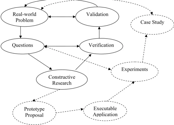
The method we used for research involves transforming the real-world problem into smaller problems, performing constructive research on each of the sub problem, validating the results of the research to find out the whether the questions are satisfactorily answered and finally having peer review to evaluate if the overall research results are really answering the real-world problem. Theses steps are looped and repeated iteratively to refine the research further and get closer to the best solution to the real-world problem. Following are the steps of the research methodology used in this thesis and also shown in figure 6.1:
1. Real-world Problem – This step involves the identification of the real-world problem. It is important to provide enough information to verify that the real-world problem identified really exists and worth to be addressed. The second most important task in this step is to define the real-world problem as accurate as possible. If the problem is not defined accurately in the first place then the results will never be fruitful at the end of the research that could last for years.
2. Questions – Here the main real-world problem is analyzed and broken down into parts or simpler questions. The purpose of this step is to provide better understanding of the main problem by taking every aspect of the problem individually. Secondly, the sub problems will be easy to solve and therefore will motivate the researchers to perform efficiently. It is necessary to mention that special care should be taken while forming the smaller problems as they could easily divert the attention of researcher from the main problem if the questions do not show relevance with the context of the research.
3. Constructive Research – This is the step where the actual research work starts. Each of the carefully designed questions is addressed separately to gather enough information to answer the question. The information on the subject of the question could be gathered by performing literature review, looking for related work done, interviews from the professionals etc…
4. Verification – This involves carefully examining the results of constructive research done for each question against the requirements of that question. The main purpose of this step is to check whether the results of the research satisfy all requirements of the question. This is necessary to perform because all the research results have to combine in later stages to draw one big solution to the main problem, therefore even one unanswered question could damage the main solution.
5. Validation – This step also performs examination of the solution but from a different point of view. The research results are assembled and reviewed by research partner collectively. This process results into having a second opinion about the outcome of the research work done that helps the researchers to decide how close they are to the perfect solution of the real-world problem. At this stage, feed back from the industry is also included that is obtained after presenting the out coming results of the research. In this regard Volvo Construction Equipment AB encouraged us a lot and showed there interest in this research work after having looked into the results of this thesis.
If the results are not satisfactory then the loop is repeated with the modified problem definition, making some assumptions or changes to reflect the real-world problem more effectively and produce better results. The above mentioned steps form a loop that presents an iterative research methodology used in this research work. The research methodology could be extended using some additional steps that are represented with dotted lines in figure 6.1. Those additional steps are more towards practical research work that are described as follows:
Real-world Problem Questions Constructive Research Verification Validation Prototype Proposal Executable Application Experiments Case Study
• Prototype Proposal - This step continues after constructive research step proposing a prototype of the solution that has been created after the research work and literature survey. The proposal could provide information how the results could be implemented and tested for correctness.
• Executable Application – This step simply transforms the prototype solution into a form that could be executed on to some platform to execute and produce practical results. This will help us to visually observe the advantages and effects of the new founded results.
• Experiment – This step includes a controlled environment in which the implementations of the research outcome are tested against the requirements of the questions created in earlier stages. The executable application created in the previous step could be used in the experiment to examine and verify the results against the requirements.
• Case Study – Once the experiments are found successful the implementation could be taken to a step higher as a case study into the industry. Then the results of that case study could be validated on a higher level against the real-world problem.
6.2
Problem Definition
This thesis addresses the problem of investigating the support of real-time database management system in component-based architecture for vehicular system. There are several challenges related to the problem because such option has been unexplored in the case of vehicular systems.
Currently, vehicle-control systems are lacking databases to manage data. Data is being stored within nodes in the system and exchanged when desired. But this could only help when the amount of data in vehicle-control system is not increasing as time passes. Increasing amount of data has made it impossible to solve the data management issues in vehicular systems without a database. Therefore, need is raised for support of database management system into vehicular system that fulfills all the real-time requirements as well as those necessary to integrate with the system. This problem could be defined as follows:
“How can a component technology for vehicular software support a real-time database management system to produce the functionality, including all essential attributes, desired for a real-time embedded vehicle-control system?”
The above defined problem obviously has parts that need to be highlighted. Firstly, the component technology is especially designed for vehicular systems. Secondly, the database management system should have real-time attributes. Thirdly, the component technology should have support for the database management system not the other way round. Lastly, the essential attributes mentioned in the problem belongs to the vehicular system.
6.3
Research Questions
After defining the real-world problem, according to the research methodology described in section 6.1 it is time to break down the main problem into sub problems. The main problem could accept several answers because it is very broad in nature, therefore the sub problems are formulated to explore particular possibilities for solving the main problem. Q1. What are the essential attributes of a vehicular system? Or which attributes are essential according to the demands of the vehicle industry?
Q2. What is required there either DBMS or RDBMS or Object Oriented database? Is it a good idea to distribute the data among the nodes in the vehicle and have a centralized database also?
Q3. What are the essential integration issues that need to be focused to discuss how the two systems would integrate physically? What is actually expected from the integration of real-time database system and the component technology?
6.4
Contributions
To address the research questions discussed in the previous section we have performed literature surveys, discussions with industrial staff and took help from senior researchers. We had a meeting with senior staff of vehicle industry about the idea of introducing a real-time database management system in vehicular systems. Master thesis, Licentiate thesis and doctoral thesis written for this research by senior researchers were also the major source of information to understand the subject.
Contributions answering Q1
Q1. What are the essential attributes of a vehicular system? Or which attributes are essential according to the demands of the vehicle industry?
This question highlights the importance of the attributes of a vehicular system that are found essential to run the system. In other words, attributes that should be the part of the final outcome are to be discussed here. This also includes the demands of vehicle industry being mapped against the attributes of vehicular system.
Extensive literature surveys were conducted to find out the attributes of a vehicular system. It has been concluded that the essential attributes are different for different types of people like customers, manufacturers, stakeholders etc… [6-2] the type of business defines the attributes that are to be designed into the architecture of vehicular systems. Therefore, it is very important to know the point of view through which the essential attributes are to be defined. In this question we are only considering the demands of the vehicle industry so the essential attributes according to the manufacturers are going to be discussed here, regardless of the type of business they want to do.
According to [6-1], there are two types of requirements from the industry categorized as the technical requirements and development process related requirements. Some of the requirements from both the categories that are highly graded are briefly described as follows:
• Analyzable – the system should be easily analyzable to predict the timing behavior and memory consumption. This attribute could be incorporated by adding some well tested components to the component model to analyze and monitor the functional characteristics of the system.
• Testable & Debuggable - Testing is very important part of software development lifecycle. The system should have the property for easily identifying errors and also correcting them as soon as possible. With component based approach testing has become easier since each component could be tested separately prior to system testing. This will help finding bugs and errors at the earliest.
• Portable – The system should be constructed with minimum dependencies with the system resources. In other words, it should be platform independent to the highest degree possible. This will increase the portability of the system that will increase the number of platforms the system can operate on, hence also increasing its reusability.
• Introducible – This property will help minimize risk related with the technology. Introducing a new technology in the development process could bring great loss to the business; therefore the technology could be divided and introducible in parts to the system.
• Maintainable – The maintainability factor is always appreciated by the business community since they are focusing more on future profits. With the component approach it should be taken care of that the components could easily be changed, modified or constructed in such a way that need little modifications. This requirement also talks about the tools that are used to diagnose and handle components for maintenance.
• Reusable – The main advantage of using component based development is the reusability factor. The components are designed in such a way that they could be reused for several types of vehicles. This is also the reason why such approach is used for the development of huge product lines. The components could only more reusable when they are constructed more in general terms. Components constructed for specific task running in a specific environment could not be used for other environments. It also raises the issue of version and variant management as well as the component repository management, where all the components are stored.
In another case study presented in [6-3], most of the attributes mentioned are common to that mentioned above. The additional attributes not mentioned yet are:
• Safety – It is the property that cannot be checked on component level. When talking of safety, environment has to be considered in the context to analyze the hazards and dangers that could be expected from the environment. Therefore,
![Figure 2.1 Overview of the electronic system architecture in Volvo XC90 [1-6]](https://thumb-us.123doks.com/thumbv2/123dok_us/1672445.2729943/18.918.158.701.235.624/figure-overview-electronic-architecture-volvo-xc.webp)
![Figure 4.1 The basic architecture of COMET [4-4]](https://thumb-us.123doks.com/thumbv2/123dok_us/1672445.2729943/24.918.200.667.430.799/figure-basic-architecture-comet.webp)
![Figure 4.4 the steps needed to create a working MiniLine system [4-3]](https://thumb-us.123doks.com/thumbv2/123dok_us/1672445.2729943/29.918.290.610.111.590/figure-steps-needed-create-working-miniline.webp)
![Figure 5-1 The AutoComp Technology [5-6]](https://thumb-us.123doks.com/thumbv2/123dok_us/1672445.2729943/31.918.188.715.111.545/figure-the-autocomp-technology.webp)