DOI : 10.5121/ijnsa.2010.2416 213
EFFECTIVE VOICE CALLS ADMISSION FOR
A
UTHORIZED USER IN INTER VOIP NETWORK
Subashri T
1, Vaidehi V
21,2
Department of Electronics, MIT Campus, Anna University, Chennai-44
tsubashri@annauniv.edu1, vaidehi@annauniv.edu2
ABSTRACT
IP based voice transmission technology is a flexible, simpler and a cost effective implementation of voice transmission. It provides a real convergence of various networks. This voice transmission technology does not support a quality that is equivalent to digitized voice, which is available in the existing PSTN networks. In addition to this, data network vulnerabilities affect the VOIP service causing a drop in the utilization of voice communication. In this paper, the quality of service for voice calls is ensured with the integration of CAC mechanism with the bandwidth link utilization which makes an estimation of the demanded bandwidth. In terms of security, prevention of ARP cache poisoning attack is achieved by use of the signed MAC address response in local area networks. It makes the network confident that the admitted user is an authorized user and also it verifies that only the authorized users’ information is exchanged over the local area network. Also an approach that makes it difficult for the hacker’s to hack the data exchanged over the quality channel has been proposed.
KEYWORDS
Bandwidth link utilization, CACA, LU-CAC, MAC addresses Hash value.
1.
I
NTRODUCTIONWith the growing speed of large scale internet industry it is now possible to transmit all real time data over the internet protocol. The internet protocol plays a major role in the real time services offered in the internet world. One such technology is voice over internet protocol. Sending digitized voice over the internet protocol is an approach to make voice call. VOIP is an attractive technology and it is adopted in home and business environments, because of their cheaper call rates compared to the PSTN based fixed networks and it also provides greater flexibility in terms of added features in addition with the existing voice communication techniques. As the IP based networks do not have CAC mechanisms the new flow would suffer packet loss and/ or significant delay. To prevent this, QoS is guaranteed for both new and existing calls by the decision making process of CAC mechanism, introduced in the IP networks. The PSTN network consists of call admission control mechanism. If the number of calls exceeds the capacity of the links, the request for new calls will be rejected while all the other calls in progress continue without any problem. The admission of a voice call is done by the CACA (Call Admission Control Agent) [1]. But in the case of IP based VOIP networks, this CAC mechanism is not provided, and hence QoS will not be guaranteed. The traffic which keeps entering the network even beyond the networks capacity limit consequently causes both the existing and the new flows to suffer packet loss and /or significant delay [2]. By the CAC mechanism integrated with the call manager, the rejection of voice calls and QoS is guaranteed. A very important aspect from the corporate point of view for the lack of success of VOIP technology is its security. VOIP technology is integrated with the workplace making the hacker’s job easier if packets are routed through unsecured data packets on a public network.
The transmissions of speech across data networks are mostly vulnerable to attacks. Thus the attacker poses a threat to the security services which is available in the VOIP network. Different
214 attacks cause several changes towards the secured information. Depending on the kind of attack several changes have to be made to the security of a network. Some of the security attacks may prevent use of all the available user resources. Thus all the services and features available to the enhanced users are destroyed making the purpose of the VOIP communication a failure due to this security problem. Quality ensured user authentication is very important for VOIP conversation. Without this verification for authentication, all the calls may get dropped even if the user resource quality is enhanced. In this paper, an approach which ensures that the authorized user is able to get the enhanced QoS guaranteed channel for their communication is provided by the integration of CAC mechanisms with user authentication procedure at the server [3]. This paper is organised as follows: chapter 2 gives the details of admission of voice calls, chapter 3 presents proposed method for securing ARP cache poisoning and chapter 4 discusses the experimental results for admission of voice calls using delay analysis and continued by the verification of prevention of ARP cache poisoning attack. Finally, conclusion is given in the chapter 5.
2. Admission of voice calls using delay analysis method in differentiated Services
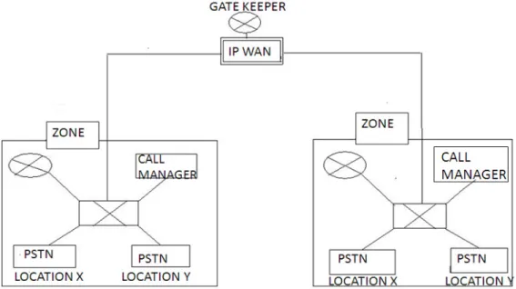
Call manager provides the overall framework for communication within a corporate environment. Gatekeeper provides address translation and admission control services to the calls. Call manager and gatekeeper communicate with each other by using the H.323 signalling protocol as shown in Figure 1. A location defines the topological area connected to other areas by links with a limited bandwidth that are registered to a call manager. A zone is a collection of H.323 endpoints that have been registered with the gatekeeper.
Figure 1. Block Diagram of the VOIP system
Call Manager as well as Gatekeeper performs admission control for calls between locations in a zone or calls between zones, aiming to provide a certain degree of QoS to voice over IP networks. To call within a zone, only the Call Manager located in the enterprise environment is invoked to perform CAC. However, for a call traversing multiple zones, not only Call Managers but also the related Gatekeeper may be involved to perform CAC.
The QoS-provisioning system is integrated into the current VoIP systems to enable both Site utilization based Call Admission Control (SU-CAC ) and Link Utilization based Call Admission
215 Control (LU-CAC) to be well utilized and supported. With this system, the overhead of resource reservation at the core routers will be pushed to the agents in the QoS-provisioning system, which overcomes the weakness of the current VoIP system [2] in applying the LU-CAC, performing resource allocation to better support the SU- CAC mechanism.
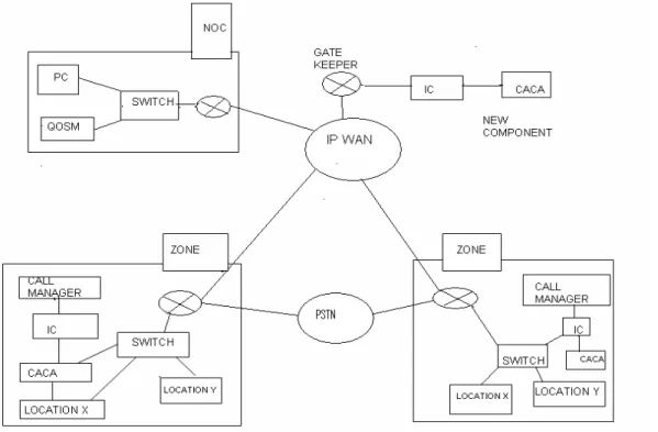
F igure 2. Block Diagram of QoS Provisioning VoIP system
This VOIP QoS-provisioning system consists of a Call Admission Control Agent (CACA) and the Integration Component (IC) as shown in Figure 2. The CACA has two modules. They are Utilization Computation Module and Admission Decision Module. The Integration Component (IC) integrates CACA with the existing VoIP systems. IC in the VOIP system provides call signalling process modules to monitor and intercept the call setup signalling from Gatekeeper or Call- Manager, and retrieves the useful message and passes it to the CACA. Call admission decision is made by the CACA.
2.1 Components of the QoS-Provisioning System
Figure 3. Components of the QoS-provisioning system
Figure 3 shows the components of QoS provisioning system. The function of QoS manager is to provide user interface to control and monitor components. It provides registration to the distributed agents and ordination among the distributed agent in the same QoS domain. It co-operates with the peer QoSMs that belong to other QoS.
There are two sub modules on call admission control agent, namely utilization computation module, and admission decision making module. Utilization computation module performs
216 deterministic (or) statistical delay analysis to obtain the maximum bandwidth utilization. The admission control is done with specific CAC mechanism by using the admission decision making module.
2.2 Existing solutions for call admission control mechanism
It is necessary to frame a methodology for providing absolute differentiated services for real time applications which can be used to derive delay bounds without specific information on flow population [6]. S. Wang and D. Xuan authors has proposed a method which employs a utilization based admission control approach for flow admission which does not require delay computation at admission time, and hence scalable to larger systems. Static Priority Schedulers [3] in differentiated service networks assign priorities on a class by class basis, with the same priority for each class and on each router [5], Thus allowing different routers to assign different priorities to classes achieving significantly higher utilization bounds in the absolute estimation of differentiated services[9][12].
As priority assignment has direct impact on the delay performance of individual packets in static-priority networks, it must be carefully addressed. In the DiffServ domain, applications are differentiated by their classes. Accordingly, previous studies [4],[7],[8] assume that priorities are assigned on a class basis only, where all the flows in a class are assigned the same priority [10],[11]. Generalized priority assignment algorithms, where the flows in a class may be assigned different priorities and flows from different classes may have the same priority.
A good survey in both absolute and relative differentiated services has been done by authors D. Xuan and R. Betti in proposed premium service model, which provides equivalent of a dedicated link between two access routers. It provides absolute differentiated services in priority driven scheduling networks with two priorities, in which the higher priority is reserved for premium service [7]. An algorithm which provides both guaranteed statistical rate delay bounds and address scalability through traffic aggregation and statistical making is described to provide guaranteed service without per flow state management by using a technique called Dynamic Packet State (DPS) has been proposed by S. Blake et al[10].
The admission control needs to be explicitly computed to verify delays for the new and exciting flows for every new flow request. As the number of flow requests increases, this procedure becomes too expensive [11]. In such cases, UBAC (Utilization Based Admission Control) is used [1][2]. Although UBAC was primarily proposed for pre-emptive scheduling of periodic tasks on a simple processor, it is also used for centralized systems. In the case of aggregate scheduling, flow and population insensitive delay analysis has been done [13]. Lower bounds on these analyses are a function of network utilization, max hop count and other shaping parameters that are independent of network topology. A better delay bound is derived in static priority scheduling network which primarily focuses on real time communication applications within DiffServ domains. Priority assignment methods for ring network and ATM networks are the two specific areas of concern within DiffServ domains [11].
It is observed that the existing methods are not capable of meeting the deadline requirement. Hence this paper proposed, Deterministic delay based method for guaranteeing end to end delay.
217 The Call Admission Control Agent (CACA) is a key component in the QoS- provisioning system. It consists of two modules. The utilization computation module performs delay analysis and computes the maximum bandwidth utilization. It usually runs at the configuration time. The computed utilization will be allocated to LU-CAC mechanism. At the runtime, the admission decision making module will make an admission decision for each incoming call request, based on the allocated bandwidth utilization (by the utilization computation module) and the currently consumed bandwidth. The maximum link utilization is the maximum value of the link utilization under which the end to end delay can be guaranteed with LU-CAC.
Figure. 4. Utilization verification procedure
The utilization computation module has a sub module called Link Utilization Computation. The main task of this sub module is to compute the maximum link utilization for LU-CAC by calling a procedure, named utilization verification procedure. Given the voice traffic model, the network topology, and the voice traffic deadline requirement, for any input of link utilization U, the worst-case delay (deterministic worst-case) or delay distribution (statistical worst-case) with deterministic delay analysis methods is computed as shown in Figure 4. Then, it verifies whether the link is safe or not for ensuring the end-to-end delay to meet the deadline.
Generally, there are two distinct types of delays suffered by a voice packet from source to destination: fixed and variable. Fixed delays include propagation delay, transmission delay, and so on. Variable delays arise from queuing delays in the output buffers. All fixed delays can be obtained by well-known experimental data or by using existing tools. However, it is difficult to obtain the variable delays. Therefore, all the calls currently established in the network must be known in order to compute queuing delays.
2.4 Utilization-based Deterministic Delay Analysis
If the deadline requirement is deterministic, then the worst-case queuing delay dk suffered by any voice packet and the buffer of output link ‘k’is bounded by
+
−
−
≤
u
y
u
c
c
d
k k k k k kρ
σ
1
(1) (2)218 Where ck is the capacity of the link. σ is the burst size, ρ is the average rate at the entrance of the network, uk is the utilization of the link. yk is defined as the worst case queuing delay bound suffered by any packet upstream from layer-k and it is given by,
∑
− ==
1 1 ^ k l l kd
y
(3)
+
=
y
d
kr
ρ
kσ
^ (4)By using the equation (3) and (4) we get,
d
d
d
k k r k ^ 1 ^ 1 ^ − − = − (5)d
d
d
l k k k r r ^ ) 1 ( ^ 1 ^ ) 1 ( ) 1 ( + − = + − = (6)We know that delay of link
d
l^
= r
(
σ
/
ρ
)
, therefore,d
k^
, the maximum of worst-case delays suffered by any voice packet at layer-k link servers, can be bounded as follows,
≤
+
−ρ
σ
*
)
1
(
1 ^r
d
kr
k (7)yk can be bounded as,
( 1) (
(
1
)
1 1)
1 1 ) 1 ( 1 1 ^ − = + ≤ ≤∑
∑
+
− − = − − =r
d
y
k k l l k l l k r rρ
σ
(8)Therefore the maximum end to end delay can be bounded as
(
)
ρ
σ
) 1 ( 1 ^ 2 1 ( − + ≤ + ≤ h h e e ry
d
(9)2.5 Utilization-Based Statistical Delay Analysis
If the deadline requirement is probabilistic, as in this case, dk is a random variable and Dk is denoted as its deadline. The violation probability of delay for any voice packet with the highest priority suffered at the buffer of output link k is bounded by
219 The end to end deadline violation probability can be bounded as,
(11)
The utilization-based delay analysis techniques shows that, under the given network topology and traffic model, the queuing delay or deadline violation probability at each output queue depends on link bandwidth utilization. By limiting the utilization of link bandwidth, the overall delay or deadline violation probability can be bounded. Given the deadline requirement, with the utilization-based delay analysis techniques, the maximum link utilization computation can obtain the maximum link utilization, which will be applied in the LU-CAC mechanism to perform admission control.
2.6 Site Utilization Computation based CAC (SU-CAC)
The main task of this sub module is to compute the maximum site utilization for SU-CAC. Site utilization computation SU-CAC mechanism tends to underutilize the network resource while providing end-to-end delay guarantees. The objective in the maximum site utilization computation is to optimize the overall site bandwidth utilization. The proposed maximum link utilization computation will be based on the end to end link maximum utilization computation and further splitting each maximum link utilization to the pair of sites that share this link. Given the network topology and the limitation of link, bandwidth is allocated to the voice traffic and the overall bandwidth utilization to sites is optimized as follows:
Maximize R R
u
∑
(12) Subject to R k R k∈u u
≤∑
, for each link k (13) 0R
u
≤
u
1Ru
R, for each route R (14) Wherek
u
is the maximum bandwidth of link k allocated to voice traffic R∈k represents all routes among any pair of sites R going through link k,u
R is the bandwidth of R allocated to voice traffic,u
0R and 1R
u
are the lower and upper bandwidth bounds for R allocated to voice traffic. In the above equations, (12) is the overall bandwidth utilization, (13) shows that the bandwidth preallocation to each pair of sites is being constrained by the link bandwidth limitation, and (14) is the user requirement for bandwidth preallocation to each pair of sites. This is a linear programming problem, which can be solved in polynomial time. The output, i.e., the preallocated bandwidth, will be used as the bandwidth limitation in the SU-CAC mechanism.3. Proposed Method for Securing ARP Cache Poisoning Attack
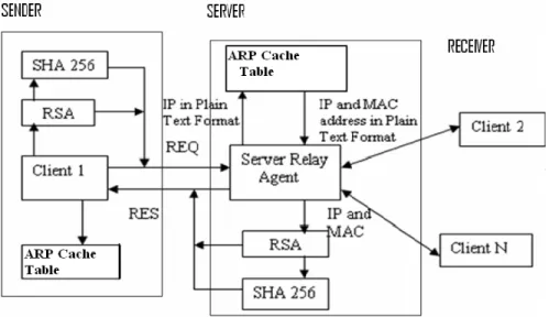
Here, an approach for the secured ARP request and response between the client and the server is proposed. The block diagram of ARP cache prevention architecture is presented in Figure 5. Client 1 needs the MAC address of the client 2 in the network for making communications. ARP program in client 1 gives the MAC address of client 2 from its ARP cache table. If client 2’s address is not found in the ARP cache table, it sends the request to the server and tries to find the MAC address of client 2. The ARP table contains the IP and MAC address of the clients. The table is available for the use of the two clients involved in the communication and
220 remains invisible to the other clients. In the server, broadcasting of ARP request results in forged ARP replies from the hackers, causing false communication between the client and the hacker. Instead of broadcasting the request to the entire network, the newly created relay agent is used for processing the secure ARP request and response. Server relay agent takes the responsibility of sending the request and replying to the client in a secured manner, thereby establishing a proper user communication between the sender and the receiver.
After the client sends a request, the server relay agent sends a response which is hashed with SHA-256 algorithm and encrypted using the RSA algorithm. Therefore only the authorised clients who are all connected to the server relay agent are permitted to exchange these ARP requests and responses in a secured manner.
Figure 5. Block diagram of ARP cache prevention architecture
Thus the authorized client can decrypt and use this secured response from the server relay agent. After some time period, if client 1 is no longer communicating with client 2, then the system delete the entries in the ARP table. So it becomes for eavesdrop to poison the ARP request and reply. Since the clients can only request the server to give the destination’s MAC address, the network broadcast overhead of ARP request is also reduced.
4. Experimental results for admission of voice calls using delay analysis method 4.1 Estimation of Queue Bandwidth
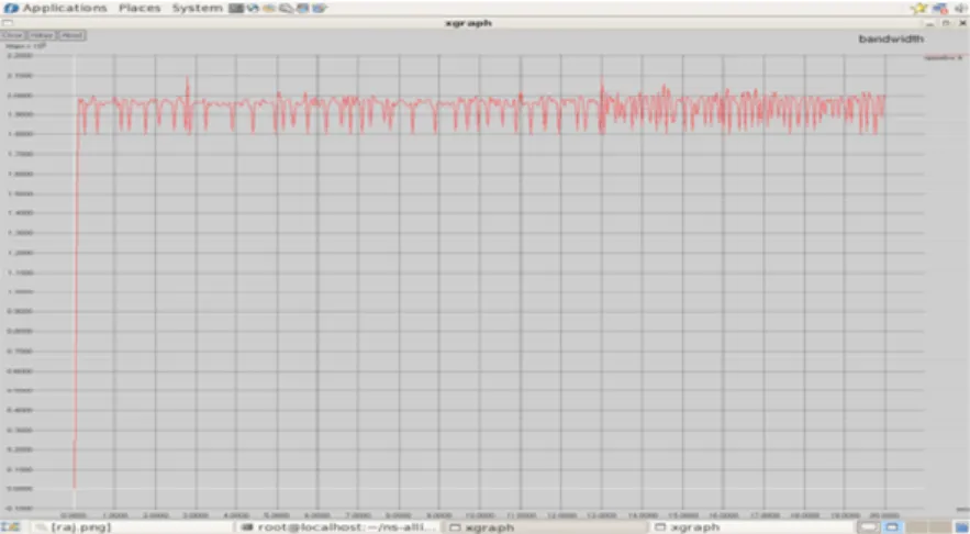
Network Simulator 2 is used to simulate the VoIP traffic. By using NS2 the queue bandwidth between the source and the destination node is simulated. In Figure 6, X axis represents time and Y axis represents bandwidth in Mbps.
221 Figure 6. Queue bandwidth
4.2 Estimation of Queue size
Queue size is calculated between the source and the destination node. Queue size is the number of packets waiting in the queue between two nodes. By using the queue size the queuing delay can
be calculated.
Figure 7. Queue Size
When the queuing delay is lesser than or equal to deterministic delay then the utilization will be safe else the utilization will not be safe. Figure 7 presents the performance of CACA for variation in queue size. In this Figure, X axis represents queue size and Y axis gives the number of calls admitted. Figure 8 presents the performance of CACA for variation in queue delay. In this figure X axis represents time and Y axis gives the number of calls admitted.
X axis- time Y axis-queue
222 Figure 8. Queue Delay
4.3 Admission decision Making Module
The admission decision making module supports both the LU-CAC and the SU-CAC mechanism. To support the LU-CAC mechanism, the admission decision making module manages the network topology information and the routing information. There are two tables in supporting this mechanism: the bandwidth table and routing table. The bandwidth table has the information about the consumed bandwidth by voice traffic and remaining bandwidth for calls as shown shown in the Table 1. The routing information can be found in the Table 2.
Once the call request comes, each link along with the call route will be checked to see if there is sufficient bandwidth available. The call route of the source and destination of the call is stored in the routing table.
Table 1: Bandwidth table
Table 2 Routing table. X axis- time Y axis- queue
223 If all the links along the call route have sufficient bandwidth left, then the CAC module will admit the call and decreases the available bandwidth for further calls. If sufficient bandwidth is not available, further calls are rejected. Once the call tears down, bandwidth requested by the call will be returned to the pool for each link along with the call route.
4.4 Simulation results of estimated and actual link
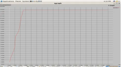
Figure 9 presents the estimated utilization of the link bandwidth as a function of time obtained using NS2. The estimated utilization represents the overall utility of link that can be used by the voice traffic. Figure 10 presents the actual utilization of the link bandwidth as a function of time. The actual utilization represents the final utility of link for incoming voice traffic through a CAC mechanism. From the maximum bandwidth utilization it is possible to find whether the utilization is safe or not. For a period of 0.000 seconds to 0.002 seconds, the link bandwidth is not allocated to any of the users. .
Figure 9. Estimated Link Utilization
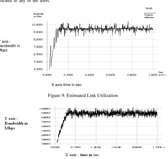
Figure 10. Actual Link Utilization
For a period of 0.18 seconds to 1.00 seconds the users are allowed to use an average of 95% bandwidth. The estimated utilization of link is obtained by using the utilization based delay analysis method. The actual utilization represents the final utility of link for incoming voice traffic through a LU-CAC mechanism. For a period of 0.00 to 0.02 seconds, the link bandwidth is not used by any of the users. From a period of 0.18 seconds to 1.00 seconds the users are allowed
X axis-time in sec Y axis
-Bandwidth in Mbps
224 to use an average of 86.5% of bandwidth out of 95% of bandwidth. Some of the voice calls are blocked, where the requested bandwidth is more than that of the available bandwidth.
4.5 Packets drop of analysis
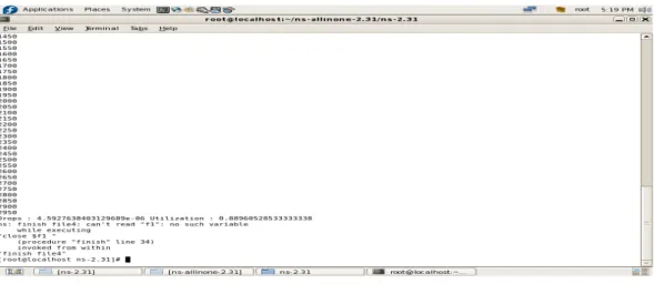
For a simulation period of 3000 seconds the total packets dropped is about 0.4% of original packets and the final utilization is about 88.9%. This is given in the Figure 11. Our utilization-based delay analysis techniques show that, under the given network topology and traffic model, the queuing delay or deadline violation probability at each output queue depends on the link bandwidth utilization. By limiting the utilization of link bandwidth, the overall delay or deadline violation probability can be bounded. Given the deadline requirement, with the utilization-based delay analysis techniques, the maximum link utilization can be computed, which will be applied in the LU-CAC mechanism to perform admission control.
Figure 11 Simulation of packets drop of LU-CAC mechanism
When the maximum link utilization is determined it is given as input to the utilization based delay analysis block. The Admission Decision Making Module can make the admission decision for the incoming calls, based on the overall bandwidth and consumed bandwidth.
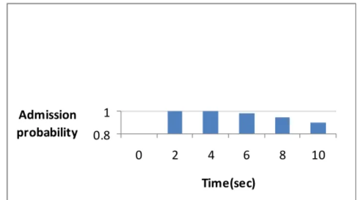
225 Poisson distribution shows the exponential loss of packets (lambda) during call utilization. The call lifetimes also increases exponentially. The packets are not blocked for calls with an average lifetime of 180 seconds. Figure 13 presents the call admission probability as a function of time. It is observed that for a period of 0 to 4 seconds all the users get admitted offer which of user admission gets reduced due to packet loss.
Figure 14 gives the total packet drops without the CAC mechanism and with the CAC mechanism. Here Y axis represents the total number of dropped packets and X axis represents the time in seconds. For a period of 0 to 10 seconds there is no packet drops with CAC mechanism. But in the other case, the total number of packet drops gets increased even from zero seconds without CAC mechanism.
0.8 1 0 2 4 6 8 10 Time(sec) Admission probability
Figure.13. Probability of call admission as a function of time
Figure.14. Packet drops with and without CAC mechanism
4.6 Performance of authenticated user voice admission procedure in VOIP Network
A call admission control mechanism offers service for 2 calls simultaneously. Due to limitations in space, only 4 calls are accepted for serving. Assuming with an example that 12 calls are arriving per day, their arrival pattern is determined to hold possion distribution. The service time for 2 simultaneous calls is exponentially distributed with µ = 8 calls per day. Hence their average number of calls in the service station, the average number of calls waiting for service and the average call lifetime can be calculated using the possion. The increase in performance of
226 authenticated and unauthenticated user’s access to the channel for voice calls are analyzed using probability based method. For example
Given λ= 12/day P (1) = probability of authenticated user wins all three calls S=2 and k=4 P (2) = probability of losing all three calls
µ= 8/day P (3) = probability of winning of at least one trial
P`(n)=1-p(n-1) 1 0 0
1
1
[
(
)
]
1
(
)
!(
)
S K N N SP
n
n
S
S
n
S
S
λ
λ
λ
µ
µ
µ
− = ==
∑
+
∑
−
−
Pn is the probability of n th trialP(n) is the probability of winning the trail
E (Nq) = 0
( ) *
(1
)2[1
(
)(1
)
]
0.4134
!
P
S
K
S
K
S
K
S
S
λ
ρ
ρ
ρ
ρ
µ
−
−
− −
−
−
−
=
calls (13) Where ρ= (λ/ µ S)E (N) average number of calls in the service station E (W) is average number of calls waiting for service E (Nq) is the qth user call process at service station
E (N) =E (Nq) + S -1 0
(
)
S n NS
n P
− =−
∑
= 0.4134 + 2- 1 0(2
)
n Nn P
=−
∑
=1.73 E(W)=1/ λ E(N) S-1 Where λ= µ[S-∑(S-n) Pn = 0.1646 day N=0The probability that an authenticated user wins the channel access in CAC procedure against an unauthenticated user access is found to be 2/5. If each of authenticated and unauthenticated users makes three separate requests each to CAC mechanisms, then the probability of an authenticated user to win all three calls or lose all the three calls, or to win atleast one trial conveys the utilization of bandwidth within a link by an authenticated user. Consider three trails attempted by two users, the probability of authenticated user to win the first, second and third request respectively against an unauthenticated user is given below.
P (1) = P (2) =P (3) = (2/5), P (1`) = P (2`) =P (3`) = 1-(2/5) = 3/5. If the probability for first method is chosen by unauthenticated user then the entire bandwidth of the channel will be reserved for them.
227
4.7. Verification of ARP cache poisoning attack prevention within LAN
The following steps provide the pseudo code for verification of ARP cache poisoning attack prevention within LAN:
1. Get the ARP request from client 1 using server relay agent. 2. Broadcast the ARP request to all of its LAN users.
3. Get secured ARP response at the destination and send the destination MAC address to the sender.
Client to server communication has been simulated by using java socket programming. Clients send their IP address and MAC address to the corresponding LAN server through a link. The ARP cache table in the server updates the entries about the client. Any client within the same LAN can find the MAC and IP addresses of the other clients in the network. ARP request and response does this processes. Figure 15 shows that the updated entry for two clients in the ARP cache table in the server. If the IP address of the destination node is known, then the client can make a request to the server to know the MAC address.
Figure.15. ARP cache table updation Figure.16. Finding MAC address of the for 2 destination within LAN
This action has been explained in the Figure 16. In the client, destination IP address is encrypted and its hashed code value is determined. Figure 17 shows the exchange of the encrypted IP and MAC addresses and the figure 18 shows the decryption of these addresses and hence the correct IP and MAC addresses are obtained after the transmission. Thus the IP and MAC addresses are secured in the ARP request and response. The transmitted and received hash values are found to be equal and are displayed. Decryption process is applied to receive response. Verification of the generated key and received key ensures the secured ARP response for user communication. Decryption of the secured ARP response provides the destination MAC address to the server. By comparing the hashed codes of received and the generated values the authentication of the user is verified.
4.8 Verification procedure of ARP cache poisoning attack prevention on interwork
The following steps provide the pseudo code for verification of ARP cache poisoning attack prevention between LAN:
1. Get the ARP request from Client1 using server relay agent 2. Broadcast ARP request to all servers.
228 3. Send the secured ARP response from the destination along with MIC (Message Integrity code) 4. Get ARP response from server relay agent 2 for server relay agent 1 along with MIC.
When two users communicate with each other, if a secured VOIP call ARP should exit then cash poisoning attack should be prevented. For this reason a server relay agent has been created. This ensures secured ARP request. When broadcast happens Server relay agent additionally cares about security allowing only encrypted request and encrypted response.
Step 1, client 1 sends the request in encrypted form using RSA and the MIC1. The MIC1 is generated using a collision-free one-way hash function SHA256. Message digest using SHA 256 is calculated for the encrypted IP address. This statement “Client 1 Server Relay Agent: ARP req + MIC 1: (Message Integrity Code 1)” discloses the way of client to server interaction passing ARP request with message integrity code.
In step 2, once the server relay agent1 in LAN1 receives the request from the Client1, it calculates the message digest for the received encrypted IP address to create a similar MIC1 (say, MIC1*). If MIC1= MIC1*, then the request is accepted else it will be rejected. It will check the corresponding MAC address in its ARP table. The request will be the IP address of the Client1 which is in LAN2. Since the requested MAC address is in some other LAN the server relay agent cannot reply directly to Client1. Hence the request will be broadcasted to other server relay agent outside the network. This statement “Server Relay Agent1 broadcast the request to all the servers: ARP request + MIC 1”discloses about the server broad casting of ARP request to all the servers to find the destination.
In step 3, the server relay agents in other LANs receive the request and check whether the corresponding MAC address for the request is there in its ARP table. If suppose server relay agent2 in LAN2 is having the MAC address for the requested IP address, it will reply to the server relay agent1 in LAN1. Server relay agent2 of LAN2 will get the public key of server relay agent1 of LAN1. Then it will encrypt the IP and MAC address and will calculate the message digest using SHA256 for the encrypted value. The response will be an encrypted value and MIC2 created using SHA256. This statement “Server Relay Agent 2 Server Relay Agent 1 ARP response + MIC 2”discloses the response of the sever relay 2 for the request of server relay 1. This response consists of identity of server relay agent 2.
In step 4, the server relay agent1 in LAN1 receives the response from server relay agent2 in LAN2. It will calculate the message digest for the received encrypted value. Then it checks whether the calculated message digest and the received message digest are equal. If both are equal, then it will send the response to the Client1 in LAN1. The response includes encrypted IP and MAC address and its MIC say MIC3.This statement “Server Relay Agent 1 ARP response + MIC 3” discloses the response of sever relay agent 1 with its own identity. In step 5, the client receives the response and calculates the message digest for the received MIC and checks for the equality with the received MIC’s. If both are equal, then it will decrypt the message and update the ARP table with the received time, else it will discard the reply and start requesting the server for the MAC address. Finally, the host A sends an acknowledgment. This statement “A Server Relay Agent 1: ACK” discloses the acknowledgement of server relay1.
4.9 Secured ARP request and ARP response analysis on internetwork
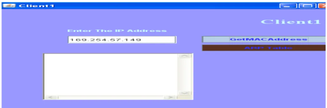
Figure 17 presents simulation of client 1 dialog module exchange with client 2 which gives the retrieval of client 2 MAC address for connectivity. After the entering destination address, client 1
229 encrypts the destination IP address using RSA algorithm and also encrypted IP address is given to hash algorithm to generate hash code for clients’ identity.
Figure 17: Finding destination MAC address between 2 clients.
Figure 18 presents the encrypted IP address for the user in LAN1 along with its message integrity code. Figure 19 and 20 present secured ARP response information exchange with transmission and reception. Figure 21 presents the comparison of generated and received hash code after the reception of secured response and Figure 22 presents the updation of destination MAC address by the sender.
Figure 18: Encryption of destination IP address and hashing of destination IP address.
Figure 19: Secured ARP Response information Figure 20: Reception of secured ARP exchange from server 2 to server 1. response in server1 from server 2.
230 Figure 21: Comparison of generated and Figure 22: Updation of MAC address by the received hash Code sender.
In Figure 14, it is shown that in LU-CAC mechanism there is no packet drops below 10 sec. When a certain number of users try to get the link, only some of them are allowed to get the bandwidth based on the estimation of maximum utilization of link in the end to end estimation. If this end to end delay estimation is based on LU-CAC method, then the estimation of maximum utilization of the link is effectively calculated. The estimated average bandwidth by this method can be given assurance up to 86.5%. After the authenticated user’s entry into the network area if he gets connected to unauthenticated user, then the entire bandwidth estimation will be used by the unauthenticated user. In a wired environment, the user’s connectivity is based on the user’s MAC address. Mapping IP address to MAC address is done by Address Resolution Protocol. ARP cache table maintains client’s MAC address on the server cache. If cache table has the unauthenticated user’s MAC address, there is a possibility of unauthorized user’s voice calls getting connected. Hence there is reduction in bandwidth utilized by authorized users. To prevent this problem secured ARP request and secured ARP response is proposed.
Instead of allowing ARP response as such to the server ARP cache table, server allows only the secured ARP response to be updated by the ARP cache table. Figure 22 and 15 presents the time taken for detecting secured ARP request and ARP response and the updation of decrypted ARP response address informations in the ARP cache table. From these figures, the time taken for the complete secured ARP request and ARP response have been found as 700ns in inter LAN and 500ns within the LAN. So the total time to verify the user’s authentication will not affect the VoIP packets transmission inside the LAN environment. Hence this method offers the effective utilization of maximum bandwidth available by only the users who are assured to be authenticated.
5 Conclusion
By integrating the Call Admission Control Agent (CACA) into the current VoIP system, the overall system can achieve high resource utilization while invoking relatively low overhead. In this paper, one of the confidentiality threats viz, ARP cache poisoning attack is considered and solution to the VOIP network system is proposed. Also, only secured clients are connected to the server and the server is allowed to provide client’s IP-MAC mapping and their connectivity only to the intended client on the server’s entry table. To provide message integrity for both client and the server, cryptographic hash function SHA256 is used. And for providing authentication for both the ends, RSA public key cryptosystem is used. RSA encrypts the network IP address and
231 client’s MAC address so that only the intended participants are allowed to decrypt and verify authentication at both ends. If a hacker tries to eavesdrop between the client and server, hacker cannot generate the message digest value of the client. So the Client’s MAC address cannot be viewed by the hacker thus making the communication secure.
REFERENCE
[1] S.Wang, D.Xuan, R.Bettai, “Providing Absolute Differentiated services for Real time Application in Static priority scheduling networks,” IEEE/ACM Trans. Networking, Vol.12, pp.326-339,2004. [2] S.Wang, D.xuan,R.Betta, and W.zhao, “Differentiated Services with statistical Real Time
Guraratees in static priority scheduling networks,” Proc. IEEE Real time systems symp.Dec.2001. [3] S.Chong and S.Li, Characterization based connection control for guaranteed services in high speed
networks,” Proc.IEEE Infocom,Apr.1995.
[4] S.Jamin,s.Shenkar,and P.Danzig, “Comparison of measurement basd admission controller-load service,” Proc. IEEE Infocom,Apr.1997
[6] Christina L.Abad, “An analysis on the schemes for detecting and preventing ARP cache poisoning attack” IEEE processing ICDCSW’07
[7] R.Siva Kumar,T. Kim, N.Venkitataman and V.Bharghavan, “Acheieveing per flow weighted rate fairness in a core stateless network, processdings of IEEE ICDCS, march 2000.
[8] K.Nicols, jacobson, L.Zhang, A Two-bit differentiated services architecture for the internet, Internet Draft, Nov.1997.
[9] R.L.Cruz,SCED+: “Efficient management of quality of service guarantees, Proceedings of IEEE INFOCOM, March, 1998.
[10] S.Blake, D.Blake, M.Carlson, E.Davies, Z.Wang, and W.Weiss, “An architecture for differenciated service”, RFC 2474,December 1998.
[11] I.Stocia,H.Zhang, Providing guaranteed without per flow management, proceedings of ACM SIGCOMM, August 1999.
[12] A.Dailians and A.Bovoupoulis, Real time admission control algorithms with delay and loss guarantees in ATM networks, IEEE proceedings, IEEE Proceedings of INFOCOM’94, 1994. [13] G.Agarwal, B.Chen, W.Zhao,and S.Davari, “Guraranteeing Synchronous message deadlines with
times token protocol,”Proc.IEEE Int’1 Conf.Distributed Computing Systems, June 1992.
Authors
V. Vaidehi received her B.E. in Electronics and Communication Engineering from College of Engineering, Guindy, M.E. in Applied Electronics and Ph.D. from Madras Institute of Technology, Chennai. She was a recipient of academic exchange fellowship of Association of Common wealth Universities. She has carried out funded projects on Tracking Algorithm for ship borne RADARS — funded by LRDE; GPS signal simulator — funded by Ministry of Information Technology; University Micro satellite — funded by ISRO; Semantic Intrusion Detection System — funded by Xambala Inc. Multi Sensor Data and Image Fusion, Power optimization in Wireless Sensor Network-funded by TCS. Currently she is a Professor and Head of Department of Information Technology, Madras Institute of Technology, Chennai. Her areas of interests are Networking, Parallel processing and Embedded systems.
232 Ms.T.Subashri received her B.E in Electronics and Communication Engineering from Thiayagarajar College of Engineering, Madurai, M.E in Communication Systems from Thiayagarajar College of Engineering, Kamaraj University, Madurai. Her areas of interests are Networking, cryptography & Network Security, Communication Systems. Currently she is pursuing her PhD from Anna University. hoto