Generating, evaluating and visualizing construction schedules
with CAD tools
Kathleen McKinney
a,), Martin Fischer
b,1a
Center for Integrated Facility Engineering, Department of CiÕil and EnÕironmental Engineering, Construction Engineering and Management Program, Building 550, Room 553-N, Stanford, CA 94305-4020, USA
b
Department of CiÕil and EnÕironmental Engineering, Construction Engineering and Management Program, Stanford, CA 94305-4020, USA
Abstract
Collaborative AEC technologies centering around component-based CAD models support architectural and structural perspectives. The construction perspective is often neglected because an important dimension for construction–time–is missing. Construction planners are forced to abstract CAD model building components into schedule models representing
Ž .
time. 4D-CAD 3D-CADqtime removes this abstraction by linking a 3D building model and schedule model through associative relationships. Adding time to 3D-CAD models extends the use of CAD tools from the design phase to the construction phase. Although commercial 4D tools exist that allow planners to build 4D models and create graphic simulations of the construction process, these tools lack features to support analysis of these models, easy generation and manipulation of such models, and realistic visualizations of the construction process. This paper discusses these shortcom-ings, highlights requirements for CAD tools to support construction planning tasks, and describes our efforts to develop 4D tools that generate 4Dqx models that more realistically represent the construction process.q1998 Elsevier Science B.V.
Keywords: 4D-CAD; Construction planning; Interaction; Visualization; Knowledge representation
1. Introduction
Construction managers develop construction plans to meet clients’ cost and time requirements, to com-municate a plan to project participants, and to pre-vent costly construction errors. Typically,
construc-Ž
tion planners interpret design documentation 2D or
.
3D drawings and specifications to produce a con-struction schedule consisting of a set of activities and
)
Corresponding author. Tel.:q1-650-723-1312; fax:q 1-650-725-6014; e-mail: [email protected].
1
Tel.:q1-650-725-4649; fax:q1-650-725-6014; e-mail: [email protected].
Ž .
sequential relationships Fig. 1A . While construc-tion schedules communicate time and the sequence
Ž
of construction activities, project participants gen-eral contractor, subcontractors, clients, designers,
.
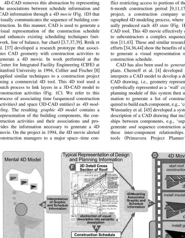
etc. must mentally associate this schedule informa-tion with the descripinforma-tion of the physical building. This mental 4D model represents the associations
Ž . Ž
between time the schedule and space the building
. Ž .
model Fig. 1B . Without a visual representation of this mental 4D model, participants must rely solely on their ability to interpret the abstract schedule and the 2D or 3D design documents. Furthermore, if project information changes, designers and planners must mentally visualize how design or schedule changes affect the overall sequence of construction.
0926-5805r98r$19.00q1998 Elsevier Science B.V. All rights reserved. Ž .
4D-CAD removes this abstraction by representing the associations between schedule information and
Ž .
CAD information through a 4D moÕie Fig. 1D that visually communicates the sequence of building con-struction. In this manner, CAD is used to generate a visual representation of the construction schedule
Ž
and enhances existing scheduling techniques
net-.w x
work, line of balance, bar chart 3,7,37,39 . Retik et
w x
al. 37 developed a research prototype that associ-ates CAD geometry with construction activities to generate a 4D movie. In work performed at the
Ž .
Center for Integrated Facility Engineering CIFE at
w x
Stanford University in 1994, Collier and Fischer 8 applied similar techniques to a construction project using a commercial 4D tool. This 4D tool used a batch process to link layers in a 3D-CAD model to
Ž .
construction activities Fig. 1C . We refer to this
Ž
process of associating time sequenced construction
. Ž .
activities and space 3D-CAD entities as 4D mod-eling. The resulting graphic 4D model contains a representation of the building components, the con-struction activities and their associations and pro-vides the information necessary to generate a 4D movie. On the project in 1994, the 4D movie alerted construction managers to a major space–time
con-flict restricting access to portions of the site during a
w x
6-month construction period 9,11,17 . In another project, a construction company used a chore-ographed 4D modeling process, where planners
man-Ž .
ually produced each 4D state Fig. 1E with a 3D-CAD tool. This 4D movie effectively communicated to subcontractors a complex sequence of
construc-w x
tion 11,43 . These and similar research and industry
w x
efforts 34,36,44 show the benefits of using 3D-CAD to generate a visual representation of an existing construction schedule.
CAD has also been used to generate construction
w x
plans. Cherneff et al. 4 developed a system that interprets a CAD model to develop a description of a CAD drawing, i.e., geometry representing a wall is symbolically represented as a ‘wall’ component. The planning module of this system then uses this infor-mation to generate a list of construction tasks re-quired to build each component, e.g., ‘construct wall’.
w x
Winstanley et al. 45 developed a system that uses a description of a CAD drawing that includes relation-ships between components, e.g., ‘supported-by’, to generate and sequence construction activities using these inter-component relationships. Commercial
Ž w
tools Primavera Project Planner , KETIV’s
ARCHTw
, Precision Estimating—Extended
Edi-w w
.
tion , AutoCAD R14 exist that allow planners to extract quantity information and then link this infor-mation to a construction schedule. These systems, however, use traditional schedule representations, such as critical path networks, and do not use the CAD information from which the schedule was gen-erated to represent the schedule information Õisually in 3D.
These efforts demonstrate how 3D-CAD models can be used for construction planning and can pro-vide the opportunity to investigate how different types of spatial situations constrain or control the sequence and duration of construction. Our 4D-CAD work continues this investigation by exploring how we can use CAD information to generate more real-istic schedules and visualize planning information in
Ž
what we refer to as 4Dqx models time, space, and
additional types of planning information, e.g., cost,
.
productivity, interference . This paper describes this vision of 4D-CAD and the functionality of the next generation 3D and 4D tools needed to generate 4Dqx models. We use a construction planning
example that highlights planning situations that are not adequately addressed with today’s planning tools
Ž .
and methods traditional and 4D and that illustrate the functionality necessary to build, visualize, and represent 4Dqx models.
2. Motivation: a test case example
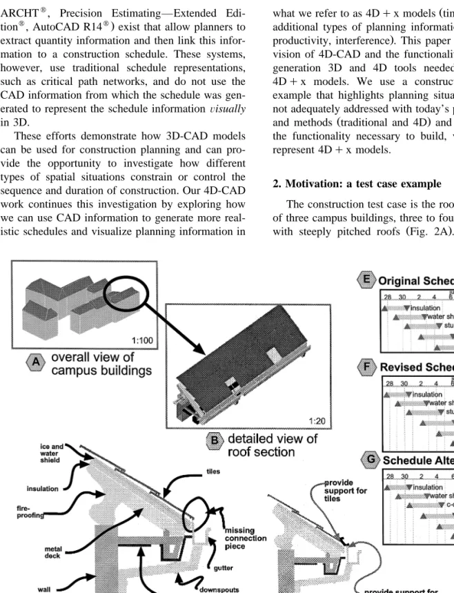
The construction test case is the roof construction of three campus buildings, three to four stories high,
Ž .
with steeply pitched roofs Fig. 2A . During roof
installation, contractors discovered that the gutter could not be installed since the assembly pieces for the gutter were not within the scope of any
subcon-Ž .
tractor. Upon review of the gutter detail Fig. 1F , the subcontractors observed that the current design was inadequate. Thus, the architect and subcontrac-tors had to redesign the roof–gutter assembly and resequence the roof construction activities.
The type of gutter assembly, however, depended on the sequence of construction. The gutter assembly needed to have a piece or pieces that supported the main gutter to the roof edge and supported the
Ž .
bottom edge of the roof tiles Fig. 2D . If a single c-channel had been chosen, then the sheet metal crew would have had to install the entire gutter assembly prior to the roof tiles. If a double c-channel had been chosen, the sheet metal contractor would have had to install the connection piece during roof construction and the gutter after the roofing contrac-tor had completed its work.
The contractors, after considering such issues, selected the sequence shown in Fig. 2F. However, the subcontractors discovered that the roof soffit stucco was cracking from the deflection of the steel structure that was caused by the weight of the roof tiles. Once again, the planners had to stop construc-tion work and resequence the construcconstruc-tion so that the tiles could be installed prior to the stucco. As these scenarios show, design as represented in 3D models and construction schedules as represented in time-based models are often inextricably linked, and inte-grated tools are necessary to explore the impact of design and construction decisions.
In the following sections, we use a set of scenar-ios based on this example to demonstrate how we envision construction planners using 4Dqx models
for planning and replanning the roof construction. We show how current tools do not adequately ad-dress the spatial and temporal issues presented in these scenarios. The scenarios are grouped into three task sets pertaining to the major tasks required for the planners to generate, visualize, and represent 4Dqx models of the roof construction.
2.1. Interaction tasks
These tasks include building and editing the 4D models to evaluate alternative construction
se-quences of the roof and identify potential problems. We show that more interactive 4D modeling meth-ods will improve planners’ ability to generate 4D models quickly and that multi-representation of 3D-CAD information will support the collaborative gen-eration of 4D models.
2.2. Knowledge tasks
These tasks include using the knowledge in the 4D models to perform computer analysis of 4Dqx
models to adequately understand planning criteria. We demonstrate the need for standard representation of 4D information and for mechanisms to capture semantic relationships between components within a 3D-CAD environment.
2.3. Visual tasks
These tasks include the viewing of planning infor-mation represented by a 4Dqx model to understand
and gain access to planning information. We illus-trate how current 4D movies do not realistically visualize the construction process and describe the need for visualizing the results of the 4D analysis in the form of visual annotation and temporary con-struction components such as scaffolding, and zones or stages of construction.
3. Interaction tasks
Today, the purpose of building 4D models is primarily for visualization and communication. Cur-rent commercial 4D tools require planners to plan and schedule before they use a 4D tool since they have to generate and coordinate a priori a 3D-CAD model and construction schedule. As a result, these tools simply provide features to ‘associate’ or ‘link’ CAD and schedule information for the purpose of generating a 4D movie. This kind of 4D modeling is non-interactive and does not truly provide the oppor-tunity for planners to use 4D tools for planning and to explore the relationships between the design and the construction schedule. Current 4D tools make it difficult for planners to feasibly use 4D models for construction planning in the sense that they cannot easily generate and compare alternative 4D models.
In this section, we present planning scenarios that illustrate these limitations and show how more inter-active features that support generation, manipulation, and elaboration of 4D content can improve the use of 4D tools for construction planning.
3.1. Interacting with 4D content
Consider the following scenario: ‘‘How can the planners rapidly build 4D models of the roof?’’ Construction on the roof has stopped. The general contractor and subcontractors decide to build three 4D models toÕisualize and compare their options. A
detailed 3D-CAD model of the roof and the original roof schedule exist as shown in Fig. 2C and E. Using commercially aÕailable software, the planners try to build three alternatiÕe 4D models.
One option for the planners is to create a series of images depicting the state of construction on a
par-Ž .
ticular day. When the images or 4D states Fig. 1E are shown in sequence, they visually communicate the sequence of roof construction. This method re-quires up front planning or story boarding to design each 4D state according to the construction schedule. This can be a time consuming process and provides the planners with little opportunity to explore alter-nate construction sequences. Nevertheless, planners
Ž .
can create accurate and realistic 4D movies using
w x
this method as shown by Dillingham in a video 11 . Another option is to use a 4D tool that enables a construction planner to ‘associate’ or ‘link’ 3D-CAD entities with construction activities. There are several ways to perform this ‘association’ or ‘linking’ pro-cess with commercial 4D tools. One method is a ‘batch process’ where the 4D tool associates an imported construction activity with an imported CAD
Ž .
layer or CAD entity Fig. 3A . Tools using this
w x
method 10 require the planner to organize the CAD model to match the construction schedule. For exam-ple, the planner must assign the CAD entities repre-senting the gutter building component to a CAD layer or a CAD group or block. When the CAD information is imported into the 4D tool, the planner associates the construction activity ‘install gutter’ with this CAD layer or group via a dialog box. Another option for the planners is to use rules that automatically perform the association. For example, a rule could associate the CAD layer ‘install gutter’ to the construction activity ‘install gutter.’ This method requires the planners to carefully coordinate the layer names and construction activity names. If a change is made to the design of the gutter or to the schedule the planner must update the CAD and
schedule information independently and perform this linking or 4D modeling process again.
Another method is to use a tool that allows the planner to interactively ‘link’ a construction activity
w x Ž .
with a CAD layer or entity 10,44 Fig. 3B . 4D tools that use this method provide varying degrees of interaction with the CAD and schedule information. With some tools, the planner must import both the CAD and schedule information into the 4D environ-ment. Within the 4D environment, the planner can directly select CAD entities and associate those enti-ties with a construction activity. For example, the planner can select the entities visually representing the metal deck to associate them with the construc-tion activity ‘install metal deck’. This linking pro-cess can be somewhat tedious and slower than a ‘batch process’ method since the planner must man-ually assign an association between each construc-tion activity and a CAD entity. However, the planner can edit these associations and some 4D tools allow
w x
the planner to edit the schedule information 44 . These tools provide a way to automate to varying degrees the 4D modeling process. In doing so, how-ever, the tools provide little opportunity for the planner to interact directly with the 4D content. None of the tools allow the planner to interact with
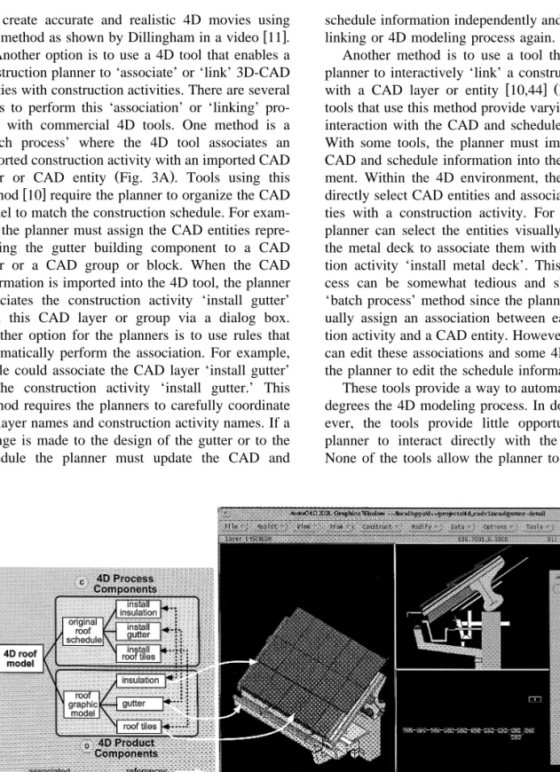
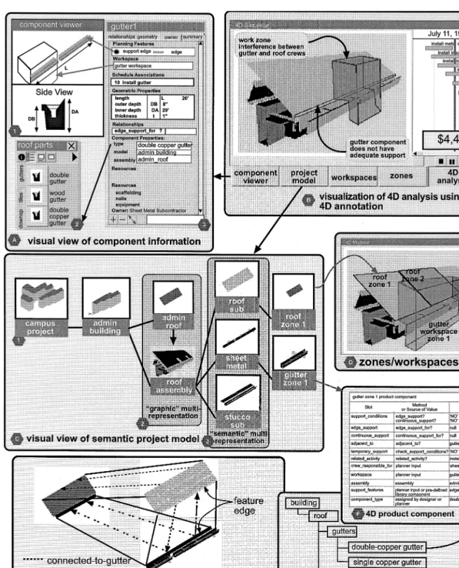
Fig. 4. CIFE 4D-CAD: screen shot of 4D environment within AutoCAD and example of semantic model in Dq qw .
both the CAD and schedule information within one 4D environment. Consequently, for the planners to build three alternative 4D models, the planners have to edit the original CAD and schedule information and then perform the 4D modeling process again. For example, the planners have to change the type of gutter and add a new connection piece. For each option, then, the planners must reassociate the CAD entities with the schedule activities. This process is repetitive and time-consuming if there are many activities.
To overcome these problems, we developed a prototype 4D tool, CIFE 4D-CAD, where planners can ‘interactively’ generate CAD, schedule, and 4D
w x Ž .
content within one environment 29 Fig. 3C . This prototype is built on AutoCADw
and linked to a
w Ž
knowledge-based engineering system, Dq q Fig. .w x
4A 21 . The planner can open the 3D-CAD model of the roof–gutter assembly and edit that model, generate or edit the schedule information, and associ-ate CAD entities with construction activities within the CIFE 4D-CAD environment. CIFE 4D-CAD
Ž
stores this information in a semantic 4D model Fig.
.
4B that represents CAD entities as 4D product
Ž .
components Fig. 4D and schedule information as
Ž .
4D process components Fig. 4C within the knowl-edge-based environment. Consequently, the planner has access to all of the 4D content—the 3D-CAD geometry, the schedule information and their associa-tions—within one 4D environment. With CIFE 4D-CAD, the planner can redesign, sequence, or re-associate CAD geometry with construction activities to quickly develop alternative construction se-quences. For example, building the three 4D models of the roof construction took a total of 30 min.
Lessons learned. 4D tools based on graphic 4D models, such as the commercial 4D tools described above, make it difficult to interact directly with the 4D content. 4D tools that store information graphi-cally and semantigraphi-cally make it easier for planners to manipulate all of the 4D content.
3.2. Interacting with 4D models
During the project construction, the general con-tractor’s overall goal was to finish roof construction and fireproof the steel structure as quickly as possi-ble. The subcontractors’ goals were to finish their
own work in a steady and continuous fashion. Thus, when the planners had to resequence the roof, they had to coordinate these conflicting goals. 4D tools today, however, allow planners to build 4D models that represent only one perspective of the project. Consequently, planners must coordinate the level of detail of the design and schedule before the 4D model is built. We envision the use of 4D tools to help contractors manage various levels of planning detail to effectively coordinate subcontractors’ work with overall project schedule objectives.
Consider the following scenario: ‘‘How could 4D tools help the planners to coordinate the production of 4D models of the roof?’’
A construction planner for the general contractor (
starts with a model of the campus project Fig.
( ))
5C 1 and wants to use a 4D tool to plan the
project. First, the planner breaks the building into
20 work packages: excaÕation, foundation, steel,
sheet metal, roof, etc. The planner then proÕides the subcontractors responsible for each work package
with releÕant design documentation and access to
the 4D project model. Subcontractors produce a 4D model of their respectiÕe portions of the construction project. For example, the roofer builds a 4D model
( from a detailed 3D-CAD model of the roof Fig.
( ))
5C 3 and a detailed schedule. When subcontractors
finish, they ‘merge’ their 4D models with the oÕerall 4D project model.
In this scenario, the project 4D model contains 3D-CAD components or entities that represent the high-level building sections, such as the roof
repre-Ž .
sented by a single surface entity Fig. 4 . The roof is represented in greater detail in CAD models pro-vided by the roof, sheet metal, and stucco
subcon-Ž Ž ..
tractors Fig. 5C 3 . The general contractor and subcontractors generate unique but related graphic and semantic views of the roof assembly. We refer to this representation of multiple forms of a building component, i.e., representing the roof assembly in
Ž .
multiple levels of detail Fig. 2A , multiple
domain-Ž .
specific views Fig. 5C , and multiple function views,
w x
as multi-representation 24 .
Various research efforts have described and demonstrated the value for multi-representation
Žsometimes referred to as multiple-views 31 , multi-w x
w x w x.
represent multifunctional and dynamic nature of de-sign and construction information. A few commer-cial CAD tools provide functionality for ‘graphic’ multi-representation of CAD entities or components. These tools allow designers to generate one or more graphic representations of the roof that are associated with a viewing scale. For example, the roof is
repre-Ž
sented as a single surface entity in 1:100 scale Fig.
. Ž .
2A and as multiple entities at 1:20 scale Fig. 2B . For construction planning, we need ‘semantic’ multi-representation of building components to gen-erate views of subcontractor-specific work, such as a sheet-metal view of a project model, or views of site-logistics, such as the representation of storage or trailer areas. Generating and coordinating multi-rep-resentations of CAD-based planning information
re-w x
quires ‘mating’ mechanisms 32 to semantically re-late one feature of a component to another feature of a component. For example, the roofer’s 3D roof assembly might contain a ‘connected-to-gutter’
fea-Ž .
ture edge Fig. 5E that ‘mates’ with a ‘connected-to-roof’ feature edge of the sheet metal’s gutter assembly. These mating mechanisms, then, manage the coordination and ‘merging’ of the individual 4D models. Furthermore, the design of the gutter and roof assemblies can easily be changed and re-designed as long as they maintain these ‘mating’ features.
Lessons learned. Planners will need 4D tools that enable the collaborative generation of 4D models that represent various levels of detail and provide planners with more opportunities to identify potential problems at any scale. To do so, CAD tools will need to support multi-representation of CAD entities and features and have ‘mating’ functionality.
4. Knowledge tasks
While these interaction features help planners build 4D models, they focus on the ‘4D’ aspects of 4Dqx models. That is, the tools focus only on
generating the temporal and spatial components of the models. In some cases, these models are suffi-cient for discovering potential problems. However, even careful review of the 4D movies of the roof construction does not necessarily reveal a missing
connection piece nor does it alert the planner to possible cracking of the stucco. In this section we show how planners can use 4D models to study these and similar planning criteria with 4D analysis. Specifically, we illustrate how standard representa-tion of 4D components, funcrepresenta-tionality to define and acquire relationships between components provide the knowledge necessary for ‘temporary support’ analysis.
4.1. Assignment of standard representation of 4D components
Temporary support refers to whether or not a building component has adequate support at the time of installation. A static analysis of the 3D-CAD model of the roof may show that all parts have support. However, if a part is scheduled to be in-stalled prior to its supporting piece or a supporting piece is missing, then the building component tem-porarily does not have support.
To perform temporary support analysis, the 4D tool needs a semantic 4D model to reason about information from 4D components and their
relation-w x
ships 27 . The research prototype CIFE 4D-CAD generates a semantic 4D model, but the 4D product components contain references to their graphic repre-sentations only and not a true description of the building components. As a result, CIFE 4D-CAD cannot infer a building component’s type or its geo-metric attributes, such as length. This component representation was sufficient to generate 4D movies rapidly from an existing non-component based CAD model but is not sufficient for 4D analysis tools that need specific types of information about the form, function, or behavior of a particular building
compo-w x
nent 16 .
Various research and industry efforts are working towards standard data models of building and con-struction information. These efforts include models
w x
designed from an architectural perspective 12 ,
si-w x
multaneous engineering perspective 30 , and
con-w x
struction management perspective 2,13 , as well as
w x
generic building product model 22,23 . Our goal is to add to these efforts by generating 4D information modeling requirements based on case studies and examples of 4D analysis.
Consider the following scenario: ‘‘How can plan-ners discover that a connection piece for the gutter is missing from the 4D model?’’
Let us assume that three 4D models are generated using a next-generation CAD tool that uses standard
[ ]
building components 22 . The planners need addi-tional information to select one of the proposed roof schedules. The planners decide to use a 4D tool that performs ‘temporary’ support analysis. The planner
obserÕes each 4D moÕie, and during the original
( )
roof sequence Fig. 2E a message notifies the plan-ner that the gutter and tiles need edge support.
The first task for the planner is to ensure that each component in the model is specified or assigned to a specific component type so that the 4D analysis can reason about specific planning information for each building component. Several research projects demonstrate methods to assign component type. One method is for planners to assign component type during modeling by selecting a component, such as ‘double copper gutter’ from a component library
ŽFig. 5A 1 . Another method is to assign componentŽ .. w x
type after modeling with ‘interpretation’ 15 . For example, the planner selects geometry representing the gutter and assigns to the geometry the component ‘double copper gutter.’
Once all of the components are associated with a standard 4D product component type, the 4D analy-sis can start. As each 4D component is virtually constructed, the system checks each 4D product component for the temporary support necessary for installation. Each component type stores the support
Ž .
conditions necessary for installation Fig. 5F , in the slot support_____conditions. For the 4D component
Ž .
gutter1 Fig. 5F the slot support_____conditions
inher-its the values ‘edge support’ and ‘continuous sup-port’ from the library component ‘double copper
Ž .
gutter’ Fig. 5G .
For each component, the 4D temporary support analysis tool checks the component’s support_____ con-ditions slot and searches for components which may
satisfy these conditions. For the ‘edge support’ con-dition, the tool fires the method edge_____support? that
looks at the value in the edge_____support slot to check
if any components are related to the gutter1 compo-nent with the ‘edge_support_for’ relation. In this example, the value is ‘null’ since no component in
the model satisfies the ‘edge-support-for’ relation. If the slot edge_____support contained a component, such
as a c-channel, then the analysis would check to see if the component had been virtually constructed at the time of gutter installation. If any of the tempo-rary support conditions are not met then a ‘NO’ value is returned and assigned to the slot
tempo-rary_____support for the gutter1 4D product
compo-nent. For example, in scenario 1 the gutter is in-stalled prior to the c-channel and thus the gutter does not have adequate temporary support.
Lessons learned. This example of 4D analysis shows how planners can use knowledge in the 4D model to generate schedule evaluations. In addition to the temporary support example, we have also generated information models for cost, damage, and
w x
productivity analysis 1 . By using such case studies we plan to develop iteratively a 4D information model that utilizes industry standard models, yet extends them for construction planning.
4.2. Functionality for acquiring relationships be-tween components
Defining standard representations of 4D compo-nents is only one part of the challenge in realizing 4D analysis. Another challenge is generating and acquiring the relationships between the components. Consider the following scenario: ‘‘How do we know the gutter is ‘supported-by’ the c-channel?’’
Let us assume that designers and planners used a next generation CAD tool that complies with
Indus-[ ]
try Foundation Class standards 22 and functional-ity to acquire and represent relationships between components. The architect builds the 3D model with pre-defined components. The gutter component con-tains a ‘support edge’ feature. As the architect adds the gutter to the roof model, this ‘support edge’ feature searches for a ‘ proÕide support’ edge feature in the 3D model. When the planner moÕes the gutter near the edge of the roof, the gutter snaps to the c-channel since the c-channel edge contains a ‘
pro-Õide support’ edge feature. Concurrently, the seman-tic 4D model stores this ‘supported_by’ relationship in the gutter component.
This scenario illustrates capturing relationships as the 3D model is produced. Some CAD tools
capture or infer geometric relationships between
w x
graphic entities or components 25 . For example, the drafting tools Ashlar Vellumw
or Imagineerw
infer that a line is drawn perpendicular to another line. The Builder System captures the ‘part-of’ relation-ship between a door and a wall as the modeler adds
w x
the door to the model 4 . Other research efforts have explored methods to capture relationships in
archi-w x
tectural drawing tools 19,26 , but commercial sys-tems are slow in adopting such functionality. Part of the problem is that the inference engines require a lot of memory and drastically reduce the speed of the modeling tool. Furthermore, this option depends upon the use of pre-defined components and relational features.
Another method is to deriÕe relationships through geometric and knowledge-based reasoning. This method uses information about CAD components, e.g., geometric location, to derive geometric-based relationships, e.g., beam1 is ‘connected-to’ column2
w18 or a pump is ‘close-to’ a control space 5 .x w x
Inference of these and other semantic relationships is not always determined by geometry or a set of rules. A variety of support conditions exist, such as ‘ad-herence-to’ or ‘hanging-from’, that are difficult to infer using rules and require highly domain specific representations of building components within CAD models.
Finally, another option is to manually interpret 3D-model components and assign relationships. In-terpretation is a useful method for assigning
seman-w x
tic or functional meaning to graphic content 6,15 . For example, the planner could specifically assign ‘supported-by’ relationships between the main gutter
w x
piece and the c-channel. Cherneff et al. 4 use this method to assign ‘connected-to’ relationships be-tween walls. This method provides the flexibility necessary to account for the unique nature of build-ing construction but also requires construction plan-ners to understand the purpose and process of assign-ing such relationships. For a small detail like the test case example, this method is feasible. For an entire construction project, however, manual interpretation adds an extraordinary amount of work required to build a 4D model.
These options complement each other, e.g., the derivation method benefits from pre-existing ‘cap-tured’ or ‘manually applied’ relationships. Since
planners will not want to manually define all of the necessary planning relationships 4D tools will need to provide the functionality outlined above.
Lessons learned. Current 4D tools generate tem-poral relationships between spatial components. Other types of relationships, however, are necessary for 4D analysis. Our goal is to define those relation-ships and investigate methods to capture them during 3D and 4D modeling.
5. Visual tasks
We have now described methods for building 4Dqx models. To make full use of the information
in these models, the visualization of a 4Dqx model
of the roof construction should alert planners to potential planning problems. This section discusses how to visualize the ‘x’ aspects of the model. We present two visual features: 4D annotation and repre-sentation of temporary construction components. 5.1. 4D annotation
Effectively communicating the 4D analysis results is critical for the planners to assess the planning criteria and evaluate the alternatives. Currently, 4D tools provide visual feedback based only on a critical path method evaluation. As the animation plays, planners can see when a component is under con-struction, complete, or on the critical path by the changing color of the component. This feedback, although useful, displays only some temporal aspects of the installation of spatial components. We suggest the use of annotation for displaying and explaining the results of the 4D analysis as illustrated in the following scenario:
The construction planners haÕe built three alterna-tiÕe 4D models. They are considering three critical issues: the temporary support of the building compo-nents, congestion during roof work, and the cost of each alternatiÕe. As the plannersÕiew the 4D moÕie, at the time the gutter is installed the edge of the gutter flashes to warn the planners of a support
( )
problem Fig. 5B . Concurrently, the 4D moÕie
Õarying degrees of congestion between the crews (Fig. 5D .)
The scenario describes examples of 4D annotation or the visual display of planning information within the time–space context. These annotations can be used to display the results of 4D analyses. Rather than simply displaying textual-based messages, anno-tation directly relates planning information to the
Ž
visual depiction of the construction process Fig.
.
5B . Well-designed visual cues will eventually en-able planners to quickly identify problem areas in the same manner that colorful images show stress ratios on structures.
Current CAD tools, however, do not provide the mechanisms to annotate 3D and 4D models. CAD information must be exported into a third party tool that provides more graphic functionality, such as
w x
interference checkers 44 . Annotation requires the following mechanisms.
Ž .1 Dynamic bi-directional links between CAD
and analysis tools. Most examples of linking analy-sis and CAD tools involve importing CAD
informa-Ž .
tion into a knowledge-based environment KBE or generating CAD information within the KBE. These links are typically uni-directional and are difficult to
w x
maintain 35 . To produce 4D annotation we need first to extract information from the CAD model to
Ž .
an analysis tool as described in Section 5.2 and then export the information back to the CAD tool.
Ž .2 Visual mechanisms to support a Õariety of annotation forms. Examples of this are flashing, highlighting, color changes, generating text, etc. Since CAD tools are designed for representation of a limited set of geometry in a static state, they do not support behavioral functionality of that geometry such as changing colors, transparency, etc. Some CAD systems support the manual generation of an-notation in the form of red-lines, bubbles, highlight-ing, etc. Most systems, though, do not have adequate
Ž .
application protocol interfaces API that allow third party developers to use the CAD environment for more sophisticated visual information displays.
Ž .3 Visual representation of inter-component rela-tionships. Even CAD tools that support representa-tion of relarepresenta-tionships provide little funcrepresenta-tionality to visualize those relationships. For example, to anno-tate the support problem for the gutter would involve
visualizing the edge of the gutter that requires sup-port. Visualizing this edge would show the planner where the problem is in the time–space context.
Lessons learned. Current CAD tools are designed to visualize building information and do not visual-ize annotative information well. Annotation function-ality is needed to visually associate analysis results with the 4D model.
5.2. Representation of temporary construction com-ponents
Consider the following scenario: ‘‘How can plan-ners use 4D models for visualizing logistics of site construction?’’
The subcontractors and general contractors haÕe
finished building seÕeral 4D models and are trying to choose one alternatiÕe. Before making a decision, the sheet metal subcontractor wants to know who is responsible for erecting the scaffolding and when the scaffolding will be aÕailable. The roofing
subcon-tractor obserÕes that the 4D model does not show
where he can stage the tiles and other roof supplies. Temporary construction components, such as tem-porary structures, equipment, staging or supply ar-eas, are just as critical to the planning and construc-tion process as the permanent building components
w42 . However, since they are not part of the perma-x
nent building structure they are not designed by the architects and engineers and often depend on the method of construction chosen by the contractor. Thus, they are typically not represented in a 3D or 4D model of the building. The 3D or 4D tools should either supply templates for these temporary construc-tion components for planners to add them to 3D models or provide mechanisms to generate these components. The Interactive Visualizer research pro-ject at the Georgia Institute of Technology is explor-ing ways to visualize construction equipment within
w x
a CAD environment 33 . Incorporating such features into a CAD-based environment will provide a more accurate visualization of a construction schedule.
Additionally, the visualization of work spaces
ŽFig. 5 , such as zones, and staging areas, is critical.
for planners to coordinate subcontractors on site
throughout a construction project. For example, an accurate representation of the roof construction needs to include the area where the roof components are being installed and the area where the roofers are storing the roofing materials. The location of this area is related to the location and duration of roof work and can therefore be represented with 4D-CAD. Planners should be able to assign functional uses of outlined areas and view the impact of work spaces and storage areas on the flow of work for project construction. The roofers may require a clearance area for safety. This area, then, should be con-strained for the time of roof installation to exclude any other construction work. However, an area for staging materials may be less restrictive, i.e., it might be possible for other work crews to share the space. Lessons learned. Today’s CAD tools are designed to produce a static state of a building design. Typi-cally, this is the completed or final-state of the building. Planners want to visualize the intermediate stages of the building and temporary construction components. CAD tools need to provide planners with components that are dynamic and have multiple states that can be dependent upon time andror
se-quence of construction.
6. Discussion: ongoing research work
Representing the construction perspective in a CAD-based environment is an ongoing effort for our 4D-CAD research group at CIFE. We are extending the use of 4D-CAD from a communication tool used by a single contractor on a limited number of pro-jects to a planning tool used by the project team. Overcoming the limitations described in this paper is a step in this direction. In addition to ongoing case studies with industry, our current research includes work in all of the areas discussed above, specified subsequently.
6.1. Interaction
We are exploring different interaction techniques for building and manipulating 4D models. One such project is the use of an interactive workbench that
w x
projects the 3D model of the building 14 . The planners can gather around the workbench and
inter-actively select building components and sequence them, quickly developing and evaluating sequence alternatives.
6.2. Knowledge
One research effort is developing a productivity modifier and cost calculator that ‘utilizes time, space, and crew information to generate cost estimates that
w x
incorporate time–space conflicts’ 1 . This research involves the representation of workspaces and con-gestion. Another research project is investigating various methods for capturing and viewing 4Dqx
information within a componentrassembly browser w x
and editor 28 . 6.3. Visual
We are currently building a prototype in VRML to demonstrate the use of features for annotation of
w x
4D models 28 . This work includes issues such as how best to display additional types of information in a visually rich 3D environment and how to visu-ally assign construction planning features to CAD components.
By collectively pursuing research in these three areas we plan to contribute to a standard representa-tion of 4Dqx models. Planners will be able to use
these models to investigate how their planning deci-sions impact the use of time and space during con-struction. This should lead to the discovery of poten-tial problems before actual construction and make the construction process more efficient.
Acknowledgements
The authors gratefully acknowledge the support of
Ž .
the Center for Integrated Facility Engineering CIFE at Stanford University and its member companies, in particular Nielsen Dillingham Builders. We thank Todd Zabelle of Pacific Contracting and Hensel Phelps employees for giving us full access to project information. We would also like to acknowledge Florian Aalami, Burcu Akinci, Eric Collier, Atul Khanzode, Jennifer Kim, Bart Luiten, Sheryl Staub, and John Kunz who have been involved in the 4D-CAD research.
References
w x1 B. Akinci, S. Staub, M. Fischer, Productivity and cost
analy-sis based on a 4D model, IT support for construction process reengineering, CIB Proc., Publication 208, Cairns, Australia, James Cook University of North Queensland, Division of Construction Management, Townsville, Queensland 4811, Australia, 1997, pp. 23–32.
w x2 G. Aouad, J. Kirkham, P. Brandon, F. Brown, T. Child, G.
Cooper, S. Ford, R. Oxman, B. Young, The conceptual modeling of construction management information,
Automa-Ž . Automa-Ž .
tion Construction 3 4 1995 267–282.
w x3 D.C. Atkins, Animationrsimulation for construction plan-ning, Proc. Eng. Construction Operations Space, Proceedings of Space 88, Albuquerque, ASCE, NM, Aerospace Div., New York, NY, 1988, pp. 670–678.
w x4 J. Cherneff, R. Logcher, D. Sriram, Integrating CAD with
construction-schedule generation, J. Comput. Civil Eng.
Ž . Ž .
ASCE 5 1 1991 64–84.
w x5 P.S. Chinowsky, K.F. Reinschmidt, Qualitative geometric Ž .
reasoner for integrated design, J. Comput. Civil Eng. 9 4
Ž1995 250–258..
w x6 M.J. Clayton, J.C. Kunz, M. Fischer, Rapid conceptual
de-sign evaluation using a virtual product model, Eng. Appl.
Ž . Ž .
Artificial Intelligence 9 4 1996 439–451.
w x7 A.B. Cleveland Jr., Real-time animation of construction
ac-tivities, Proceedings of Construction Congress I—Excellence in the Constructed Project, ASCE, San Francisco, CA, 1989, pp. 238–243.
w x8 E. Collier, M. Fischer, Four-dimensional modeling in design
and construction, CIFE Technical Report, No. 101, Stanford University, Stanford, CA, February 1995.
w x9 E. Collier, M. Fischer, Visual-based scheduling: 4D
model-ing on the San Mateo County Health Center, Proc. of the Third Congress on Computing in Civil Engineering, ASCE, Anaheim, CA, 1996, pp. 800–805.
w10 P.V. Dharwadkar, A.B. Cleveland Jr., Knowledge-basedx
parametric design using JSpace, Proc. of the Third Congress on Computing in Civil Engineering, ASCE, Anaheim, CA, 1996, pp. 70–76.
w11 Dillingham Construction, 4D CAD animated visualizationsx
of construction methods and progress for three projects Chi-ron: bridge to the future, Life Sciences CTR Project Phase 1, VA Medical Center Long Beach, San Mateo County Health Center, CIFE, Videotape, No. 024, Stanford, CA, 1994.
w12 C.M. Eastman, A. Siabris, A generic building product modelx
incorporating building type information, Automation
Con-Ž . Con-Ž .
struction 3 4 1995 283–304.
w13 T. Froese, Models of construction process information, J.x Ž . Ž .
Comput. Civil Eng. 10 3 1996 183–193.
w14 B. Frohlich, M. Fischer, M. Agrawala, A. Beers, P. Hanra-x ¨
han, Collaborative production modeling and planning, CG&A
Ž . Ž .
IEEE 17 4 1997 13–15.
w15 R. Fruchter, Conceptual, collaborative building designx Ž . Ž .
through shared graphics, IEEE Expert 11 3 1996 33–41.
w16 J.S. Gero, Design prototypes: a knowledge representationx Ž . Ž .
schema for design, AI Mag. 11 4 1990 27–36.
w17 H. Goldstein, Is virtual reality for real?, Civil Eng. 65 6x Ž . Ž1995 45–48..
w18 H. Goto, K.H. Law, G. Brickey, Knowledge-based creationx
of an architectural 3D model from 2D drawings, CIFE Technical Report, No. 59, Stanford University, Stanford, CA, December, 1991.
w19 M. Gross, Relational modeling, in: M. McCullough, M.J.x Ž .
William, P. Purcell Eds. , The Electronic Design Studio, MIT Press, Cambridge, MA, 1990.
w20 A.C. Harfmann, S.S. Chen, Component-based building repre-x
sentation for design and construction, Automation
Construc-Ž . Construc-Ž .
tion 1 4 1993 339–350.
w21 H.C. Howard, Modeling process and form for process plantx
pipe routing, Modeling of buildings through their life-cycle, CIB Proceedings 180, International Council for Building
Ž .
Research Studies and Documentation CIB , Stanford Uni-versity, Stanford, CA, 1995, pp. 523–534.
w22 International Alliance for Interoperability, Industry Founda-x
tion Classes Release 1.0, 1997 Industry Alliance for Interop-erability, Specification Vols. 1–4, Washington, DC, January 1997.
w23 ISO TC184x rSC4, Part 106: Building construction core
model, Working Draft. ISO CD 10303-106 No. NIST, Gaithersburg, MD, USA.
w24 ISOx rTC184, Part 10 Title: Conceptual Model of Parts Li-brary, ISO TC 184rSC4rWG2 ISO CD 13584-10.
w25 K. Ito, Y. Ueno, R.E. Levitt, A. Darwiche, Linking knowl-x
edge-based systems to CAD design data with an object-ori-ented building product model, CIFE Technical Report, No. 17, Stanford University, Stanford, CA, August 1989.
w26 D.L. Maulsby, I.H. Witten, K.A. Kittlitz, V.G. Franceschin,x
Inferring graphical procedures: the compleat metamouse,
Hu-Ž . Hu-Ž .
man Comput. Interaction 7 1 1992 47–89.
w27 K. McKinney, M. Fischer, 4D analysis of temporary support,x
Proc. of the Fourth Congress in Computing in Civil Engi-neering, ASCE, Philadelphia, PA, 1997, pp. 470–476.
w28 K. McKinney, M. Fischer, J. Kunz, Visualization of con-x
struction planning information, Proc. of Intelligent User In-terfaces 98, ACM, San Francisco, CA, 1998.
w29 K. McKinney, J. Kim, M. Fischer, C. Howard, Interactivex
4D-CAD, Proc. of the Third Congress in Computing in Civil Engineering, ASCE, Anaheim, CA, pp. 383–389.
w30 A. Molina, A.H. Al-Ashaab, T.I.A. Ellis, R.I.M. Young, R.x
Bell, A review of computer-aided simultaneous engineering
Ž . Ž .
systems, Res. Eng. 7 1 1995 38–63.
w31 G.A.v. Nederveen, F.P. Tolman, Modeling multiple views onx Ž . Ž .
buildings, Automation Construction 1 3 1992 215–224.
w32 B.O. Nnaji, H.-C. Liu, Product modeler for discrete compo-x Ž . Ž .
nents, Int. J. Prod. Res. 31 9 1993 2017–2044.
w33 A. Opdenbosh, M. Hastak, Virtual reality environment forx
design and analysis of automatic construction equipment, Proc. of Second Congress on Computing in Civil Engineer-ing, ASCE, Atlanta, GA, 1995, pp. 566–573.
w34 K.F. Reinschmidt, F.H. Griffis, P.L. Bronner, Integration ofx
engineering, design, and construction, J. Constr. Eng.
Man-Ž . Man-Ž .
age. 117 4 1990 756–772.
w35 K.F. Reinshcmidt, G.A. Finn, Smarter computer-aided de-x Ž . Ž .
sign, IEEE Expert 9 4 1994 50–55.
w36 A. Retik, Planning and monitoring of construction projectsx
using virtual reality, Project Management P.M.A. Finland 3
Ž . Ž1 1997 28–31..
w37 A. Retik, A. Warszawski, A. Banai, The use of computerx Ž . Ž .
graphics as a scheduling tool, Bldg. Environ. 25 2 1994 133–142.
w38 D. Riley, I.D. Tommelein, Space planning tools for multi-x
story construction, Proc. of the Third Congress in Computing in Civil Engineering, ASCE, Anaheim, CA, 1996, pp. 718– 724.
w39 W.E. Rodriguez, Visual simulation: beyond CAD and geo-x
metric modeling, Proc. of Energy-Sources Technology Con-ference, ASME, New Orleans, LA, 1994, pp. 63–68.
w40 M.A. Rosenman, J.S. Gero, M.L. Maher, Knowledge-basedx
research at the key center of design computing, in: G.
Ž .
Carrara, Y.E. Kalay Eds. , Knowledge-Based Computer-Aided Design, Elsevier, Amsterdam, The Netherlands, 1994, pp. 327–278.
w41 W.Y. Thabet, y.J. Beliveau, SCaRC: space-constrained re-x
source-constrained scheduling system, J. Comput. Civil Eng.
Ž . Ž .
11 1 1997 48–59.
w42 I.D. Tommelein, R.E. Levitt, B. Hayes-Roth, T. Confrey,x
Sightplan experiments: alternate strategies for site layout
Ž . Ž .
design, J. Comput. Civil Eng. 5 1 1991 42–63.
w43 F. Vaugn, 3D and 4D CAD modeling on commercialx
design-build projects, Proc. of the Third Congress of Com-puting in Civil Engineering, ASCE, Anaheim, CA, 1996, pp. 390–396.
w44 M. Williams, Graphical simulation for project planning: 4D-x
planner, Proc. of the Third Congress on Computing in Civil Engineering, ASCE, Anaheim, CA, 1996, pp. 404–409.
w45 G. Winstanley, M.A. Chacon, R.E. Levitt, Integrated projectx Ž . Ž .
planning environment, Intelligent System Eng. 2 2 1993 91–106.