UNIVERSITY OF OSLO
Department of Informatics
CloudML
A DSL for model-based
realization of
applications in the cloud
Master thesis
Eirik Brandtzæg
CloudML
Eirik Brandtzæg
Spring 2012
Abstract
Cloud Computing offers a vast amount of resources, available for end users on a pay-as-you-go basis. The opportunity to choose between several cloud providers is alluded by complexity of cloud solution heterogeneity. Challenges with cloud deployment and resource provisioning are identified in this thesis through experiments, performing full cloud deployments with tools offered by cloud providers. To tackle these challenges a model-based language (named CloudML), is purposed to effectively tackle these challenges through abstraction. This language is supported by an engine able to provision nodes in “the cloud”. Topologies for these nodes are defined through lexical templates. The engine supports 24 cloud providers, through software reuse, by leveraging an existing library. Sufficient metadata for provisioned instances are provided through
models@run.time approach. The engine is implemented and experiments have been conducted towards provisioning on two of the major cloud providers, Amazon and Rackspace. These experiments are used to validate the effort of this thesis. Perspectives and future visions of CloudML are expressed in the end of this thesis. This work is integrated as a part of the REMICS project.
Contents
1 Introduction 1
I
Context
4
2 Background: Cloud Computing and Model-Driven Engineering 5
2.1 Cloud Computing . . . 5
2.1.1 Characteristics . . . 6
2.1.2 Service models . . . 8
2.1.3 Deployment models . . . 11
2.2 Model-Driven Engineering . . . 12
3 State of the Art in Provisioning 16 3.1 Model-Driven Approaches . . . 16
3.2 APIs . . . 20
3.3 Deployments . . . 22
3.4 Examples of cloud solutions . . . 23
4 Challenges in the cloud 25 4.1 Scenario . . . 25 4.2 Challenges . . . 28 4.3 Summary . . . 30 5 Requirements 32 5.1 Comparison . . . 37 5.2 Requirement dependencies . . . 37
II
Contribution
38
6 Vision, concepts and principles 39
7 Analysis and design - CloudML 42
7.1 Meta-model . . . 42
7.1.1 Single node topology . . . 43
7.1.2 Three nodes topology . . . 46
7.1.3 Multi-cloud provisioning . . . 50
7.2 Technological assessments and considerations . . . 51
7.2.1 Programming language and application environment. . . . 51
7.2.2 Asynchronous information gathering and distribution. . . 51
7.2.3 Lexical format. . . 53
7.3 Modules and application flow . . . 54
8 Implementation/realization: The cloudml-engine library 57 8.1 Technology overview . . . 57
8.2 Automatic build system . . . 59
8.3 Cloud connection . . . 60
8.4 Asynchronous provisioning . . . 61
8.5 From text to objects . . . 63
8.6 Usage . . . 64
9 Validation & Experiments 66
III
Conclusion
72
10 Conclusions 73 11 Perspectives 77 11.1 Short term (implementation) perspectives . . . 77List of Figures
2.1 Cloud architecture service models. . . 8
2.2 Model-Driven Architecture. . . 14
3.1 AWS CloudFormation template. . . 17
3.2 CA Applogic screenshot. . . 18
3.3 Madeira Cloud screenshot. . . 19
3.4 Cloud drivers. . . 20
4.1 Different architectural ways to provision nodes (topologies). . . . 26
5.1 Requirements, including dependencies. . . 33
6.1 “Big picture”, overview of CloudML procedure flow. . . 40
7.1 Meta model of CloudML. . . 43
7.2 Object diagram of scenario with one node. . . 44
7.3 CloudML asynchronous provisioning process (Sequence diagram). 45 7.4 Provisioning three nodes provisioning. . . 47
7.5 Asynchronous message communication between three nodes. . . . 48
7.6 Scenario reimplemented with three nodes. . . 49
7.7 Multicloud topology. . . 50
7.8 Modules in CloudML, dependencies and orchestration. . . 55
7.9 Usage flow in CloudML. . . 56
8.1 Maven dependency graph (with and without test scope). . . 59
8.2 Code snippet of facade used incloud-connector. . . 60
8.3 Code snippet of actor model implementation (RuntimeInstane). 62 8.4 Example Maven conficuration section to include cloudml-engine. . 65
8.5 Example client (Scala) callout to cloudml-engine. . . 65
9.2 Account used for validation,JavaScript Object Notation(JSON). . 68 9.3 Code snippets of client used for validation (Scala). . . 69 9.4 Output from running validation client. . . 70 9.5 Screenshot of Amazon Web Service (AWS) console (left) and
Rackspace console (right) after provisioning. . . 71 11.1 Template including load balancer. . . 77
List of Tables
2.1 Common providers available services . . . 5 5.1 Comparing selected elements from CHAP. 3 with requirements. . . 32
5.2 Requirements associated with challenges. . . 37 8.1 Comparing lexical formats with aspects from requirements.
Weighting from zero (0) to three (3) respectively least to most supported. . . 63 10.1 Result of how requirements were tackled. . . 74
Preface
I would like to thank SINTEF, and my supervisor Arne Jørgen Berre, for providing me with this opportunity to dive into the world of Cloud Computing. I also want to thank Sébastien Mosser for his immense amount of assistance through designing and implementing of CloudML. And of course for his accommodation through the writing process of this thesis, including repeated feedback. The Scala community, Specs2 mailing list andjcloudsIRC channel have been of great assistance, guiding and helping through the implementation of CloudML.
Chapter 1
Introduction
Cloud Computing [4] is gaining in popularity, both in the academic world and in software industry. One of the greatest advantages of Cloud Computing is
on-demand self service, providing dynamic scalability (elasticity). As Cloud Computing utilizes pay-as-you-gopayment solution, customers are offered fine-grained costs for rented services. These advantages can be exploited to prevent web-applications from breaking during peak loads, and supporting an“unlimited”
amount of end users. According to Amazon (provider of Amazon Web Service
(AWS), a major Cloud Computing host): “much like plugging in a microwave in order to power it doesn’t require any knowledge of electricity, one should be able to plug in an application to the cloud in order to receive the power it needs to run, just like a utility” [32]. Although there are still technical challenges when deploying applications to the cloud, as Amazon emphasizes them selves.
Cloud providers stresses the need of technological advantages originating from Cloud Computing. They emphasize how horizontal and vertical scalability can enhance applications to become more robust. The main issue is technological inconsistencies for provisioning between providers, e.g., AWS offer Command-line interface (CLI) tools, while Rackspace only offer web-based Application Programming Interface (API)s. Although most providers offer APIs these are different as well, they are inconsistent in layout, usage and entities. The result of this isvendor lock-in, the means used to provision an application to a given cloud must be reconsidered if it is to be re-provisioned on another provider.
This thesis introduces the first version of CloudML, a modeling language designed to harmonize the inconsistencies between providers, with a model-based approach. This research is done in the context of the REMICS EU FP7 project, which aims to provide automated support to migrate legacy applications into
clouds [22]. With CloudML users can design cloud topologies with models, and while provisioning they are provided “run-time models” of resources under provisioning, according to models@run.time approach [5].
Accompanying this thesis is a research into “state-of-the-art” technologies and frameworks. This background information give an overview, indication the position of cloud evolution today (April 2012). An experiment is conducted to outline the challenges with cloud provisioning today. From these challenges a set of requirements are constructed, which will be referred to throughout the thesis. The goal of CloudML is to address these requirements, and this is approached through visioning, designing and implementing CloudML. Finally an experiment is carried out to validate the implementation of CloudML.
Publications.
• Paper presented at BENEVOL’11: Sébastien Mosser, Brandtzæg, Ei-rik, and Parastoo Mohagheghi. Cloud-Computing: from Revolution to Evolution (published). InBElgian-NEtherlands software eVOLution sem-inar (BENEVOL’11), workshop: (extended abstract), , pages 1–2, Brussels, Belgium, December 2011. VUB. This paper introduces the motivation of the global approach for CloudML.
• Paper accepted at Cloud’12: Eirik Brandtzæg, Parastoo Mohagheghi, and Sébastien Mosser. Towards a Domain-Specific Language to Deploy Applications in the Clouds. In Third International Conference on Cloud Computing, (CLOUD’12), July 2012. This paper build a deployment model on top of the contribution in this thesis.
• Technical report for Deliverable D4.1: Gorka Benguria, Andrey Sadovykh, Sébastien Mosser, Antonin Abhervé, and Bradtzæg, Eirik. Platform Independent Model for Cloud (PIM4Cloud). Technical Report D-4.1, EU FP7 REMICS, March 2012. This report describe a global overview of the migration process of Reuse and Migration of legacy applications to Interoperable Cloud Services(REMICS).
• Paper submitted to Cloud the MDE workshop, associated with theEuropean Conference on Modelling Foundations and Applications (ECMFA): Eirik Brandtzæg, Sébastien Mosser, and Parastoo Mohagheghi. Towards CloudML, a Model-based Approach to Provision Resources in the Clouds
(submitted). In Workshop on Model-Driven Engineering on and for the Cloud (CloudMDE 2012), co-located with ECMFA’12, Lyngby, Danemark, July 2012. Springer LNCS. This paper introduces the design and early requirements of CloudML.
Involvement in REMICS. REMICS is a 5, 7 M e project, and part of the
7th Framework Program. Its main goal is to migrate legacy application, e.g., software written in COBOL or old versions of Pascal, to modern web-based application for the cloud. Some of the partners in REMICS are SINTEF (Norway), Dome consuling (Spain), Tecnalia (Spain), Fraunhofer FOKUS (Germany), Netfective (France), DI Systemer (Norway) and SOFTEAM (France). My involvement in REMICS is CloudML, which focuses on the last step in the process of the project, which is deploying these application to cloud environments.
I have been involved in REMICS Deliverable D4.1 (PIM4Cloud, Work package 4). I have attended two project meetings consulting PIM4Cloud and respectively CloudML. The first one at Dome consulting, Palma de Mallorca (June 2011). The second project meeting by traveling withHurtigrutenfrom Tromsø to Trondheim (September 2011).
Part I
Context
Chapter 2
Background: Cloud Computing and
Model-Driven Engineering
In this chapter the essential background topics for this thesis are introduced. The first topic is Cloud Computing, a way of providing computing power as a service instead of being a product. The second topic is about Model-Driven Engineering and Model-Driven Architecture and these in relation to Cloud Computing.
2.1
Cloud Computing
Cloud Computing is gaining popularity and more companies are starting to explore the possibilities as well as the limitation of the cloud. A good example of cloud adaptation in a large scale scenario is when the White House moved their
recovery.gov [16] operation to a cloud infrastructure, this was estimated to save them $750,000 at the current time, and even more on a long-term basis.
Table 2.1: Common providers available services
Provider Service Service Model
AWS Elastic Compute Cloud Infrastructure
AWS Elastic Beanstalk Platform
Google Google App Engine Platform
CA AppLogic Infrastructure
Microsoft Azure Platform and Infrastructure
Heroku Different services Platform
Nodejitsu Node.js Platform
The definitions under are mainly based on definitions provided by theNational Institute of Standards and Technology(NIST) which is one of the leaders in Cloud Computing standardization. The main providers of Cloud Computing in April 2012 are Google, Amazon with AWS [1] and Microsoft. A non-exhaustive list of common providers is reproduced in TABLE. 2.1.
2.1.1
Characteristics
Cloud Computing is about providing computation as services [21], such as virtual instances and file storage, rather than products. Cloud characteristics are what define the difference between normal hosting and computing as a service.
On-demand self-service. Withon-demand self-service, consumers can achieve provisioning without any human interaction. On-demand means dynamic scalability and elasticity of resource allocation, self-service so that users do not need to manually do these allocations themselves. Considering an online election system, for most of the year it will have low usage demands, but before and under election days it will have to serve a humongous amount of requests. With on-demand self-servicethe online election system could automatically be given more resources such as memory, computation power or even increase the number of instances to handle peak loads. The previous example has planned (or known) peak intervals, so even though automatic handling is appealing it could be solved by good planning. But sometimes predicting peak loads can be difficult, such as when a product suddenly becomes more popular than first anticipated. Twitter is a good example of a service that can have difficulties in estimating the amount of user demand and total amount of incoming requests. For instance in the year
2011 they achieved a record of25, 088 Tweets Per Second (TPS), triggered by a Japanese television screening of the movie “Castle in the Sky”. Each “tweet”
essentially becomes at least one request to Twitter services. On a normal basis the service does not have to cope with this amount of requests, so this event was a strong and unpredicted fluctuation in day-to-day operations, and this is the kind of scenarios that Cloud Computing can help to tackle with characteristics such as on-demand self-service. With on-demand self-service allocation will automatically scale upwards as popularity increases and downwards as resources become superfluous.
Broad network access. When working cloud with solutions, in form of man-agement, monitoring or other interactions it is important that capabilities are avail-able over standard network mechanisms, supporting familiar protocols such as
Hypertext Transport Protocol(HTTP)/HTTPS and Secure Shell(SSH). So users can utilize tools and software they already possesses or will have little difficulty gaining, such as web browsers. This is what the characteristicbroad network ac-cess is all about, ensuring familiar mechanisms for communicating with a cloud service. Most cloud providers also provide web based consoles/interfaces that users can use to create, delete and manage their resources.
Resource pooling. Physical and virtual resources are pooled so they can be dynamically assigned and reassigned according to consumer demand. Users do not need to be troubled with scalability as this is handled automatically. This is a provider side characteristic which directly influenceon-demand self-service. There is also a sense of location independence, users can choose geographical locations on higher abstracted levels such as country or sate, but not always as detailed or specific as city. It is important that users can choose at least country as geographical location for their product deployments, for instance to reduce latency between product and customers based on customer location or data storing rules set by government.
Rapid elasticity. Already allocated resources can expand vertically to meet new demands, so instead of provisioning more instances (horizontal scaling) existing instances are given more resources such asRandom-access Memory(RAM) and
Central Processing Unit (CPU). Towards the characteristic of on-demand self-service allocation can happen instantly, which means that on unexpected peak loads, the pressure will be instantly handled by scaling upwards. It is important to underline that such features can be financially problematic if not limited, because costs reflect resource allocation.
Measured service. Resources allocated in the cloud can be monitored by cloud providers, accommodating end users with monitoring data on resources they rent. Can be used for statistics for users, for instance to do analytical research on product popularity or determine user groups based on geographical data or browser usage. The providers themselves use this information to handle on-demand services, if they notice that an instance has a peak in load or has a
IaaS
PaaS
SaaS
Figure 2.1: Cloud architecture service models.
noticeable increase in requests they can automatically allocate more resources or capabilities to leave pressure. Measuringcan also help providers with billing, if they for instance charge by resource load and not only amount of resources allocated.
2.1.2
Service models
Service modelsare definitions of different layers in Cloud Computing. The layers represent the amount of abstraction developers get from each service model. Higher layers have more abstraction, but can be more limited, while lower levels have less abstraction and are more customizable. Limitations could be in many different forms, such as bound to a specific operating system, programming language or framework. There are three main architectural service models in Cloud Computing[21] as seen as vertical integration levels in FIG. 2.1, namely
Infrastructure-as-a-Service (IaaS), Platform-as-a-Service (PaaS) and Software-as-a-Service(SaaS). IaaS is on the lowest closest to physical hardware and SaaS on the highest level close to runnable applications.
IaaS. This layer is similar to more standard solutions such as Virtual Private Servers (VPS), and is therefore the service model closest to standard hosting solutions. Stanoevska-Slabeva [31] emphasizes that “infrastructure had been available as a service for quite some time” and this “has been referred to as utility computing, such as Sun Grid Compute Utility”. Which means that IaaS can also be compared to grid computing, a well known computing model in the academic world.
“
The capability provided to the consumer is to provision processing, storage, networks, and other fundamental computing resources where the consumer is able to deploy and run arbitrary software, which can include operating systems and applications.MELL AND GRANCE[21]
This underline the liberty thisservice modelprovides to users, but this also means that developers need to handle software and tools themselves, from operating system and up to their application. In some cases this is advantageous, for instance when deploying native libraries and tools that applications rely on such as tools to convert and edit images or video files. But in other cases this is not necessary and choosing thisservice model can be manpower in-effective for companies as developers must focus on meta tasks.
“
The consumer does not manage or control the underlying cloud in-frastructure but has control over operating systems, storage, deployed ap-plications, and possibly limited control of select networking components (e.g., host firewalls).MELL AND GRANCE[21]
Users have control over which operating system they want, in some cases users can only pick from a set of pre-configured operating systems. It is common for providers to include both Linux and Windows in their selections. Some providers such as Amazon let users upload their own disk images. A similarity to VPS is that operating systems are not manually installed, when selecting an operating system this is copied directly into the instance pre-installed and will therefore be instantly ready for usage. Examples of providers of IaaS are AWSElastic Compute Cloud
(EC2) and Rackspace CloudServers.
PaaS. Cloud Computing is built to guide and assist developers through abstractions, and the next layer in theservice modelis designed to aid developers by detaching them from configuration of operating system and frameworks.
Developers are limited to capabilities the provider support, such as programming languages (e.g., Java, C#), environments (e.g., Java Virtual Machine (JVM), .NET, Node.js), storage systems (e.g., flat files, NoSQL databases, Relation Database Management System(RDBMS)), services (e.g., load balancers, backup, content delivery) and tools (e.g., plugin for Eclipse, command line tools) [21]. For example the first versions of Google App Engine (GAE) did only support an internal key-value based database called BigTable, which is still their main database. This database is transparently interfaced using their API, but also support technologies such asJava Persistence API (JPA) and Java Data Objects
(JDO), users are bound to Java and these frameworks, and even limitations to the frameworks as they have specific handlers for RDBMS. The disconnection from operating system is the strength of PaaS solutions, on one hand developers are restricted, but they are also freed from configuration, installments and maintaining deployments. Some PaaS providers support additional convenient capabilities such as test utilities for deployed applications and translucent scaling. In the end developers can put all focus on developing applications instead of spending time and resources on unrelated tasks.
Examples of PaaS providers are Google with GAE and the company Heroku with their eponymous service. Amazon also entered the PaaS market with their service named Elastic Beanstalk, which is an abstraction over EC2 as IaaS underneath. Multiple PaaS providers utilize EC2 as underlying infrastructure, examples of such providers are Heroku and Nodester, this is a tendency with increasing popularity.
PaaS providers support deployments through online APIs, in many cases by providing specific tools such as command line interfaces or plugins toIntegrated Development Environment (IDE)s like Eclipse. It is common for the API to have client built on technologies related to the technology supported by the PaaS, for instance Heroku has a Ruby-based client and Nodejitsu has an executable Node.js-module as client.
SaaS. The highest layer of the service models farthest away from physical hardware and with highest level of abstraction.
“
The capability provided to the consumer is to use the provider’s applications running on a cloud infrastructure.MELL AND GRANCE[21]
The core purpose is to provide complete applications as services, in many cases end products. Google products such as Gmail, Google Apps and Google Calendar are examples of SaaS applications. What separates SaaS applications from other applications are the underlying cloud infrastructure. By utilizing the five characteristics of Cloud Computing, SaaS applications achieve Cloud Computing advantages.
It is not imposed that SaaS deployments are web applications, they can also consist of different technologies such as Representational state transfer (REST) APIs or SOAP services, but in any case it is most common to utilize the HTTP. In SaaS applications end users are most likely not the companies renting from providers, but instead the companies customers. The abstraction layer covers most of all aspects around an application, the only exception could be customizations and settings that end users can do albeit this can be application specific. In some cases providers have services that affect these users as well, such asSingle Sign-on.
2.1.3
Deployment models
Deployment models define where and how applications are deployed in a cloud environment, such as publicly with a global provider or private in local data centers. There are four maindeployment models.
Public cloud. In this deployment model infrastructure is open to the public, so companies can rent services from cloud providers. Cloud providers own the hardware and rent out IaaS and PaaS solutions to users. Examples of such providers are Amazon with AWS and Google with GAE. The benefit of this model is that companies can save costs as they do not need to purchase physical hardware or manpower to build and maintain such hardware. It also means that a company can scale their infrastructure without having to physically expand their data center.
Private cloud. Similar to classical infrastructures where hardware and operation is owned and controlled by organizations themselves. This deployment model has arisen because of security issues regarding storage of data in public clouds. With
private cloudorganization can provide data security in forms such as geographical location and existing domain specific firewalls, and help comply requirements set by the government or other offices. Beside these models defined by NIST there is another arising model known asVirtual Private Cloud(VPC), which is similar to public cloudbut with some security implications such as sandboxed network. With this solution companies can deploy cluster application and enhance or ensure security within the cluster, for example by disabling remote access to certain parts of a cluster and routing all data through safe gateways or firewalls. In public cloudsit can be possible to reach other instances on a local network, also between cloud customers.
Community cloud. Similar as private clouds but run as a coalition between several organizations. Several organizations share the same aspects of a private cloud (such as security requirements, policies, and compliance considerations), and therefore share infrastructure. This type ofdeployment modelcan be found in universities where resources can be shared between other universities.
Hybrid cloud. One benefit is to distinguish data from logic for purposes such as security issues, by storing sensitive information in a private cloud while computing with public cloud. For instance a government can establish by law how and where some types of informations must be stored, such as privacy law. To sustain such laws a company could store data on their ownprivate cloudwhile doing computation on a public cloud. In some cases such laws relates only to geographical location of stored data, making it possible to take advantage of
public cloudsthat can guarantee geographical deployment within a given country.
2.2
Model-Driven Engineering
By combining the domain of Cloud Computing with the one of modeling it is possible to achieve benefits such as improved communication when designing a system and better understanding of the system itself. This statement is emphasized by Boochet al.in the UML:
“
Modeling is a central part of all the activities that lead up to the deployment of good software. We build models to communicate the desired structure and behavior of our system. We build models to visualize and control the system’s architecture. We build models to better understand the system we are building, often exposing opportunities for simplification and reuse. We build models to manage risk.BOOCH ET AL. [7]
When it comes to Cloud Computing these definitions are even more important because of financial aspects since provisioned nodes instantly draw credit. The definition of“modeling”can be assessed from the previous epigraph, but it is also important to choose correct models for the task. Stanoevska-Slabeva emphasizes in one of her studies that grid computing“is the starting point and basis for Cloud Computing.”[31]. As grid computing bear similarities towards Cloud Computing in terms of virtualization and utility computing it is possible to use the same
Unified Modeling Language(UML) diagrams for IaaS as previously used in grid computing. The importance of this re-usability of models is based on the origin of grid computing,eScience, and the popularity of modeling in this research area. The importance of choosing correct models is emphasized by [7]:
“
(i)The choice of what models to create has a profound influence on how a problem is attacked and how a solution is shaped.(ii)Every model may be expressed at different levels of precision.(iii)The best models are connected to reality. (iv) No single model is sufficient. Every nontrivial system is best approached through a small set of nearly independent models.BOOCH ET AL. [7]
These definition precepts state that several models (precept(iv)) on different levels (precept(ii)) of precision should be used to model the same system. From this it is concludable that several models can be used to describe one or several Cloud Computing perspectives. Nor are there any restraints to only use UML diagrams
CIM
PIM
PSM PSM
Code Code
Figure 2.2: Model-Driven Architecture.
or even diagrams at all. As an example AWS CloudFormation implements a lexical model of their cloud services, while CA AppLogic has a visual and more UML component-based diagram of their capabilities.
Model-Driven Architecture. Model-Driven Architecture (MDA) is a way of designing software with modeling in mind provided by the Object Management Group (OMG). When working with MDA it is common to first create a
Computation Independent Model (CIM), then a Platform-Independent Model
(PIM) and lastly aPlatform-Specific Model(PSM) as seen in FIG. 2.2. There are
other models and steps in between these, but they render the essentials. Beside the models there are five different steps as explained by Singh [30]:
1. Create a CIM. This is done to capture requirements and describe the domain. To do this the MDA developer must familiarize with the business organization and the requirements of this domain. This should be done without any specific technology. The physical appearance of CIM models can be compared touse casediagrams in UML, where developers can model actors and actions (use cases) based on a specific domain.
2. Develop a PIM.The next step aims at using descriptions and requirements from the CIM with specific technologies. The OMG standard for MDA use UML models, while other tools or practices might select different technologies. Example of such Platform Independent Modelscan be class diagrams in UML used to describe a domain on a technical level.
something more concrete and specific to a platform. Several PSM and be used to represent one PIM as seen in FIG. 2.2. Examples of such models
can be to add language specific details to PIM class diagram such as types (String, Integer) for variables, access levels (private, public), method return types and argument types. Kent, Stuart [19] emphasizes the importance of this mapping in one of his studies:
“
A PSM is not a PIM, but is also not an implementation. [. . . ] In MDA, the main mapping is between PIM and PSM, and this is often associated with code generation. However, this is not the only kind of mapping required.KENT[19]
From this it is possible to determine that a PSM is more specific to a platform than PIM, such as programming language or environment.
4. Generate code form PSM.A PSM should be specific enough that code can be generated from the models. For instance can class diagrams be generated into entities, and additional code for managing the entities can be added as well. Some diagrams such as Business Process Model and Notation
(BPMN) can generateBusiness Process Execution Language(BPEL) which again can generate executable logic.
5. Deploy. The final step is based on deploying the PSM, which concludes the five steps from loosely descriptions of a domain to a running product. Different environmental configurations can be applied in step 4 to assure deployments on different systems, this without changing the PSM from step in step3.
Chapter 3
State of the Art in Provisioning
There already exists scientific research projects, APIs, frameworks and other tech-nologies which aim at consolidating, interfacing and utilizing cloud techtech-nologies. This chapter introduces some of these concepts, and does this by dividing the chapter into four parts:
1. Model-Driven Approaches that aims to present frameworks and projects that utilize models on a larger scale.
2. APIs are about frameworks that connects to cloud providers, often with multi-cloud support, these projects can be used as middleware for other systems.
3. Deployments are about projects that do full deployment of applications, inclusing provisioning. These are often more academic.
4. Lastly the chapter will discuss examples of cloud solutions, some real-world examples that might not be directly related to provisioning but are important and interesting regardless.
3.1
Model-Driven Approaches
Amazon AWS CloudFormation. [1]
This is a service provided by Amazon from their popular AWS. It give users the ability to create template files in form ofJavaScript Object Notation(JSON) as seen in FIG. 3.1, which they can load into AWS to create stacks of resources. A
stackis a defined set of resources in different amount and sizes, such as numerous instances, one or more databases and a load balancer, although what types and
1 {
2 "Description": "Create an EC2 instance", 3 "Parameters": {
4 "KeyPair": {
5 "Description": "For SSH access", 6 "Type": "String" 7 } 8 }, 9 "Resources": { 10 "Ec2Instance": { 11 "Type": "AWS::EC2::Instance", 12 "Properties": {
13 "KeyName": { "Ref": "KeyPair" }, 14 "ImageId": "ami-1234abcd" 15 } 16 } 17 }, 18 "Outputs" : { 19 "InstanceId": {
20 "Description": "Instace ID of created instance", 21 "Value": { "Ref": "Ec2Instance" }
22 }
23 },
24 "AWSTemplateFormatVersion": "2010-09-09" 25 }
Figure 3.1: AWS CloudFormation template.
sizes of resources is ambiguous. To provision a stack with CloudFormation the template file (in JSON format) is first uploaded to AWS which makes it accessible from AWS Management Console.
The template consist of three main sections, (i) Parameters, (ii) Resources
and(iii) Outputs. The Parameterssection makes it possible to send parameters into the template, with this the template becomes a macro language by replacing references in theResourcessection with inputs from users. Input to the parameters are given inside the management console when provisioning a stack with a given template. The Resource section define types of resources that should be provisioned, the Type property is based on a set of predefined resource types such asAWS::EC2::Instancein Java package style. The last section,Output, will generate output to users when provisioning is complete, here it is possible for
Figure 3.2: CA Applogic screenshot.
users to pick from a set of variables to get the information they need.
This template system makes it easier for users to duplicate a setup many times, and as the templates support parameters, this process can be as dynamic as the user design it to be. This is a model in form of lexical syntax, both the template itself and the resources that can be used. For a company that is fresh in the world of cloud computing this service could be considered too advance. This is mainly meant for users that want to replicate a certain stack, with the ability to provide custom parameters. Once a stack is deployed it is only maintainable through the AWS Management Console, and not through template files. The format that Amazon uses for the templates is a good format, the syntax is in form of JSON which is readable and easy to use, but the structure and semantics of the template itself is not used by any other providers or cloud management tooling, so it can not be considered a multi-cloud solution. Even though JSON is a readable format, it does not make it viable as a presentation medium on a business level.
CA Applogic. [10]
The Applogic platform is designed to manage CAs private cloud infrastruc-ture [28]. It also has a web based interface which let users manage their cloud re-sources as shown in FIG. 3.2 which use and benefit from a model based approach.
func-Figure 3.3: Madeira Cloud screenshot.
tionalities. This interface let users configure their deployments through a diagram with familiarities to UML component diagrams with interfaces and assembly con-nectors. They let users configure a selection of third party applications, such as Apache and MySQL, as well as network security, instances and monitoring. What CA has created is both an easy way into the cloud and it utilizes the advantages of model realizations. Their solution will also prove beneficial when conducting business level consulting as it visualizes the structural layout of an application. But this solution is only made for private clouds running their own controller, this can prove troublesome for migration, both in to and out of the infrastructure.
Madeira Cloud. [20]
Madeira have created a tool which is similar to CA Applogic, but instead of focusing on a private cloud solution they have created a tool specifically for AWS EC2. Users can create stacks with the available services in AWS through dynamic diagrams, as expressed in FIG. 3.3. Like CA Applogic their tool is also
proprietary, but on the other hand they support a free account which can be used to test their service out. One would also need a AWS account as an addition.
Thesestacksare live representations of the architecture and can be found and managed in the AWS console as other AWS services. They also support storing running systems into template files which can be used to redeploy identical copies and it should also handle configuration conflicts. For identifying servers they use hostnames, which are bound to specific instances so end users don’t have to bother with IP addresses.
Common
interface Driver - EC2 Driver -Rackspace Driver - Azure EC2 Rackspace Azure
Figure 3.4: Cloud drivers.
3.2
APIs
Extensive work have been done towards simplifying and combining cloud technologies through abstractions, interfaces and integrations. Much of this work is in form of APIs, mostly in two different forms. First as programming libraries that can be utilized directly from a given programming language or environment such as Java or Python. The other common solution is to have an online facade against public providers, in this solution the APIs are mostly in REST form. REST [15] is a software architecture for management of web resources on a service. It uses the HTTP and consecutive methods such as GET, POST, PUT and DELETE to do tasks such as retrieve lists, items and create items. APIs can be considered modeling approaches based on the fact they have a topology and hierarchical structure, but it is not a distinct modeling. A modeling language could overlay the code and help providing a clear overview, but the language directly would not provide a good overview of deployment. And links between resources can be hard to see, as the API lacks correlation between resources and method calls.
Driver. All the API solutions use the term “driver”, it represents a module or component that fit into existing software and extend the support of external connections without changing the interface. A cloud driver
connects a given software to an existing cloud provider through this providers web based API (REST), illustrated in FIG. 3.4.
jclouds. [18]
This is a library written in Java and can be used from any JVM-based language. Provider support is implemented in drivers, and they even support deployments to some PaaS solutions such as GAE. Thejcloudsdevelopers divides their library in two different parts, one for computing powers such as EC2 and one for blob
storage like S3. Some blob storage services are accessible on the compute side of the library such as Elastic Block Storage(EBS). They support “dry runs” so a stack can be deployed as a simulation, not actually deploying it to a public cloud. This is beneficial for testing deployments, and writing unit tests without initializing connections, the library enhance this by providing a stub aimed at testing.
libcloud. [3]
Libcloud is an API that aims to support the largest cloud providers through a common API. The classes are based around drivers that extends from a common ontology, then provider-specific attributes and logic is added to the implementation. Libcoud is very similar to jclouds but the API code base is written in Python. The API is Python-only and could therefore be considered to have high tool-chain dependency.
Deltacloud. [2]
Deltacloudhas a similar procedure asjcloudsandlibcloud, but with a REST API. So they also work on the term driver, but instead of having a library to a programming language, the users are presented with an web-based API they can call on Deltacloud servers. As well as having similar problems as other APIs this approach means that every call has to go through their servers, similar to a proxy. This can work with the benefits that many middleware softwares have, such as caching, queues, redundancy and transformations. The main disadvantages are single point of failure (bottleneck) and version inconsistencies. Deltacloud
provide two sets of native libraries, one in Ruby and another in C, which makes it easier to communicate with the REST API. Previously discussed jcloudsalso supportDeltacloud, as it would interface this with adriveras any other web-based API.
3.3
Deployments
There are also some solutions that specifically aim at full deployments, versus provisioning single instances or services these solutions provision everything needed to fully deploy an application with a given topology.
mOSAIC. [26]
Aims at not only provisioning in the cloud, but deployment as well. They focus on abstractions for application developers and state they can easily enable users to“obtain the desired application characteristics (like scalability, fault-tolerance, QoS, etc.)”[25]. There are two abstraction layers, one for cloud provisioning and one for application-logic. The mOSAIC solution will select a proper cloud based on how developers describe their application, several clouds can be selected based on their properties. The mOSAIC solution will use the IaaS solutions of cloud providers to deploy users application, then communication between these clouds will be done using“cloud based message queues technologies”.
RESERVOIR. [29]
Resources and Services Virtualization without Barriers (RESERVOIR) is a European Union FP7 project, aiming atcloud federationbetween private and hy-brid clouds. With this a deployed application can distribute workload seamlessly between private and public clouds based on the applications requirements. This is done by creatingReservoir sites, one for each provider. Each site is independent and run a Virtual Execution Environment (VEE) which is managed by a Virtual Execution Environment Manager (VEEM). The VEEM communicate with other VEEM and are able to do federation between clouds. Each site must have the Reservoir software components installed, which makes it self-maintainable and self-monitoring.
Vega. [11]
Vega framework is a deployment framework aiming at full cloud deployments of multi-tier topologies, they also follow a model-based approach. The description of a given topology is done by using eXtensible Markup Language(XML) files, with these files developers can replicate a stack. The XML contain information about the instances, such asostypefor Operating System andimage-description
They also allow small scripts to be written directly into the XML through a node
runoncescriptwhich can do some additional configuration on a propagated node. A resource manager keep track of resources in a system, grouping instances after their attributes.
3.4
Examples of cloud solutions
In this section real-world examples are presented, such as popular IaaS and PaaS solutions and other technologies which are widely used today. Some solutions bear strong similarities to others, such as EC2 and Rackspace cloudservers, for these only one solution will be discussed.
EC2. A central part of AWS, it was Amazons initial step into the world of cloud computing when they released EC2 as a service as public beta in 2006. This service is known to be the most basic service that cloud providers offer and is what makes Amazon an IaaS provider. When users rent EC2 services they are actually renting VPS instances virtualized by Xen. Although the instance itself can be considered a VPS there are other factors that define it as a cloud service. For instance cost calculations, monitoring and tightly coupled services surrounding EC2. Examples of these services are EBS for block storage,Elastic Load Balancer(ELB) for load balancing andElastic IPfor dynamically assigning static IP addresses to instances.
Some of AWS other services rely on EC2 such as AWS Elastic Beanstalk and
Elastic MapReduce. When purchasing these services it is possible to manage the EC2 instances through the EC2-tab in AWS console, but this is not mandatory as they will be automatically managed through the original purchased service. As mentioned earlier other PaaS solutions delivered by independent companies are using EC2 or other AWS solutions. Examples of these are Heroku, Nodester, DotCloud and Engine Yard which uses EC2. Example of companies using other AWS services is Dropbox which uses S3.
EC2 is similar to services offered by other providers, such as Rackspace cloudservers, GoGrid cloud servers and Linode Cloud. Some of the additional services such as ELB can also be found in other providers which also offer these capabilities as services.
Amazon Beanstalk. Amazon has been known for providing IaaS solutions (EC2) and services complementing either their IaaS or the Storage as a Service
solution S3. Unlike some providers such as Microsoft and Google they had yet to introduce a PaaS based solution, until they created Beanstalk. This is the Amazon answer to PaaS, it is based on pre-configuring a stack of existing services such as EC2 for computing, EBS for storage and ELB for load balancing. At the writing moment they support Java with Tomcat and PHP deployments. The Java solution is based on uploading war-files to Beanstalk, then the service will handle the rest of the deployment. For PHP the deployment is based on Git repositories, when pushing code to a given repository Beanstalk will automatically deploy the new code to an Apache httpd instance.
Chapter 4
Challenges in the cloud
As cloud computing is growing in popularity it is also growing in complexity. More and more providers are entering the market and different types of solutions are made. There are few physical restrictions on how a provider should let their users do provisioning, and little limitations in technological solutions. The result can be a complex and struggling introduction to cloud computing for users, and provisioning procedure can alternate between providers.
This chapter will outline research on which has been conducted by physical provisioning of an example application. First the scenario will be introduced, describing the example application and different means of provisioning in form of topologies. Then the challenges identified from the research will be presented.
4.1
Scenario
The following scenario is chosen because of how much it resembles actual solutions used in industry today. It uses a featureless example application meant to fit into scenario topologies without having too much complexity. Challenges should not be affected from errors or problems with the example application. The application will be provisioned to a defined set of providers with a defined set of different topologies.
BankManager. To recognize challenges when doing cloud provisioning an example application [8] is utilized. The application (from here known as
BankManager) is a prototypical bank manager system which support creating users and bank accounts and moving money between bank accounts and users. The application is based on a three-tier architecture with (i)presentation tier with
Browser Front-end And Back-end
(a) Single node.
Browser Front-end Back-end
(b) Two nodes.
Browser Load balancer
Front-end
Front-end
Back-end
(c) Three nodes.
Browser Load balancer
Front-end 1
Front-end 2
Front-end n
Back-end
(d) Several front-ends.
Browser Load balancer
Front-end 1 Front-end 2 Front-end n Back-end master Slave 1 Slave 2 Slave n
(e) Several front-ends and back-ends (slaves).
Browser Non-system interaction
Node Provisioned instance
Load balancer
Load balancer as a service
Connection flow n-times
(f) Legend.
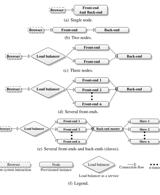
Figure 4.1: Different architectural ways to provision nodes (topologies). a web-based interface,(ii)logic tier with controllers and services and(iii)database tier with models and entities. Three or more tiers in a web application is a common solution, especially for applications based on theModel View Controller (MVC) architectural pattern. The advantage with this architecture is that the lowest tier (database) can be physically detached from the tiers above, the application can then be distributed between several nodes. It is also possible to have more tiers, for instance by adding a service layer to handle re-usable logic. Having more tiers and distributing these over several nodes is an architecture often found in
Topologies. Some examples of provisioning topologies are illustrated in FIG. 4.1. Each example includes a browser to visualize application flow,
front-end visualizes executable logic and back-end represents database. It is possible to have both front-end and back-end on the same node, as shown in FIG. 4.1(a). When the topology have several front-ends a load balancer is used to direct traffic between browser and front-end. The
load balancer could be a node like the rest, but in this cloud-based scen-ario it is actually a cloud service, which is also why it is graphically different. In FIG. 4.1(b)front-endis separated from back-end, this introduces the flex-ibility of increasing computation power on thefront-endnode while spawning more storage on theback-end. For applications performing heavy computations it can be beneficial to distribute the workload between severalfront-endnodes as seen in FIG. 4.1(c), the number of front-endscan be linearly increased n
number of times as shown in FIG. 4.1(d).BankManageris not designed to handle severalback-endsbecause of RDBMS, this can be solved at the database level with master and slaves (FIG. 4.1(e)).
Execution. The main goal of the scenario is to successfully deploy BankMan-ager on a given set of providers with a given set of topologies. And to achieve such deployment it is crucial to perform cloud provisioning. The providers chosen are (i)AWS [1] and(ii)Rackspace [27]. These are strong providers with a re-spectable amount of customers, as two of the leaders in cloud computing. They also have different graphical interfaces, APIs and toolchains which makes them suitable for a scenario addressing multi-cloud challenges.
The topology chosen for this scenario have three nodes, FIG. 4.1(c). This topology is advanced enough that it needs a load balancer in front of two
front-endnodes, and yet the simplest topology of the ones that benefits from a load balancer. It is important to include most of the technologies and services that needs testing.
To perform the actual provisioning a set of primitive Bash-scripts are developed. These scripts are designed to automate a full deployment on a two-step basis. First two-step is to provision instances:
• Authenticate against provider. • Create instances.
The second step is deployment:
• ConfigureBankManager to use one of provisioned instances IP address for database.
• BuildBankManagerinto aWeb application Archive(WAR)-file. • Authenticate to instance using SSH.
• Remotely execute commands to install required third party software such as Java and PostgreSQL.
• Remotely configure third party software.
• Inject WAR-file into instances usingSSH File Transfer Protocol(SFTP). • Remotely startBankManager.
The scripts are provider-specific so one set of scripts had to be made for each provider. Rackspace had at that moment no command-line tools, so a REST client had to be constructed.
4.2
Challenges
From this example it became clear that there were multiple challenges to address when deploying applications to cloud infrastructure. This thesis is scoped to cloud provisioning, but the goal of this provisioning step is to enable a successful deployment (see CHAP. 11). It is therefore crucial to involve a full deployment in
the scenario to discover important challenges.
Complexity. The first challenge encountered is to simply authenticate and communicate with the cloud. The two providers had different approaches, AWS [1] had command-line tools built from their Java APIs, while Rackspace [27] had no tools beside the API language bindings. So for AWS the Bash-scripts could do callouts to the command-line interface while for Rackspace the public REST API had to be utilized. This emphasized the inconsistencies between providers, and resulted in an additional tool being introduced to handle requests.
As this emphasizes the complexity even further it also stresses engineering capabilities of individuals. It would be difficult for non-technical participants to fully understand and give comments or feedback on the topology chosen since important information got hidden behind complex commands.
Feedback on failure. Debugging the scripts is also a challenging task, since they fit together by sequential calls and printed information based on Linux and Bash commands such asgrepandecho. Error messages from both command-line and REST interfaces are essentially muted away. If one specific script should fail it would be difficult to know (i)which script failed,(ii)at what step it was failing and(iii)what was the cause of failure .
Multi-cloud. Once able to provision the correct amount of nodes with desired properties on the first provider it became clear that mirroring the setup to the other provider is not as convenient as anticipated. There are certain aspects of vendor lock-in, so each script is hand-crafted for specific providers. The most noticeable differences would be (i) different ways of defining instance sizes, (ii) different versions, distributions or types of operating systems (images), (iii)different way of connection to provisioned instances . The lock-in situations can in many cases have financial implications where for example a finished application is locked to one provider and this provider increases tenant costs. Or availability decreases and results in decrease of service uptime damaging revenue.
Reproducibility. The scripts provisioned nodes based on command-line argu-ments and did not persist the designed topology in any way. This made topologies cumbersome to reproduce. If the topology could be persisted in any way, for ex-ample serialized files, it would be possible to reuse these files at a later time. The persisted topologies could also be reused on other clouds making a similar setup at another cloud provider, or even distribute the setup between providers.
Shareable. Since the scripts did not remember a given setup it is impossible to share topologies“as is”between coworkers. It is important that topologies can be shared because direct input from individuals with different areas of competence can increase quality. If the topology could be serialized into files these files could also be interpreted and loaded into different tools to help visualizing and editing.
Robustness. There are several ways the scripts could fail and most errors are ignored. They are made to search for specific lines in strings returned by the APIs, if these strings are non-existent the scripts would just continue regardless of complete dependency to information within the strings. A preferable solution to this could be transactional behavior with rollback functionality in case an error
should occur, or simply stop the propagation and throw exceptions that can be handled on a higher level.
Metadata dependency. The scripts were developed to fulfill a complete deployment, including (i)provisioning instances,(ii)install third party software on instances, (iii) configure instances and software, (iv) configure and upload WAR-file and (v) deploy and start the application from the WAR-file . In this thesis the focus is aimed at provisioning, but it proved important to temporally save run-time specific metadata to successfully deploy the application. In the
BankManager example the crucial metadata is information needed to connect front-end nodes with the back-end node, but other deployments is likely to need the same or different metadata for other tasks. This metadata is collected in step
(i), and used in step(iii)and step(iv).
4.3
Summary
There are many cloud providers on the global market today. These providers support many layers of cloud, such as PaaS and IaaS. This vast amount of providers and new technologies and services can be overwhelming for many companies and small and medium businesses. There are no practical introductions to possibilities and limitations to cloud computing, or the differences between different providers and services. Each provider has some kind of management console, usually in form of a web interface and API. But model driven approaches are inadequate in many of these environments. UML diagrams such as deployment diagram and component diagram are used in legacy systems to describe system architectures, but this advantage has yet to hit the mainstream of cloud computing management. It is also difficult to have co-operational interaction on a business level without using the advantage of graphical models. The knowledge needed to handle one provider might differ to another, so a multi-cloud approach might be very resource-heavy on competence in companies. The types of deployment resources are different between the providers, even how to gain access to and handle running instances might be very different. Some larger cloud management application developers are not even providers themselves, but offer tooling for private cloud solutions. Some of these providers have implemented different types of web based applications that let end users manage their cloud instances. The main problem with this is that there are no
standards defining a cloud instance or links between instances and other services a provider offer. If a provider does not offer any management interface and want to implement this as a new feature for customers, a standard format to set the foundation would help them achieve a better product for their end users.
Chapter 5
Requirements
In CHAP. 4 challenges were identified, in this chapter those challenges will be addressed and tackled through requirements. The requirements are descriptions of important aspects and needs derived from the previous chapter. A table overview will display consecutive challenges and requirements. This table is angled to the challenges point of view to clarify requirements relation to challenges, and one requirement can try to solve several challenges.
The requirements are expressed in FIG. 5.1. Four of these requirements have
dependencies to each other. These dependencies are shown through lines linking the requirements together.
The requirements from CHAP. 5 are compared against selected technologies and frameworks from CHAP. 3. These comparisons are expressed in TABLE. 5.1. ; R1 : Software reuse. There were several technological difficulties
with the scripts from the scenario in CHAP. 4. And one requirement that could
leverage several of the challenges originating from these particular issues would be to utilize an existing framework or library. If possible it would be beneficial to not“Reinvent the wheel”and rather use work that others have done that solve the same problems. In the chapter CHAP. 3 multi-cloud APIs were described, such as libcloud and jclouds. The core of this requirement is to find and experiment
Table 5.1: Comparing selected elements from CHAP. 3 with requirements.
State of the art software-reuse foundation mda m@rt lexical-template
Amazon CloudFormation Yes No Yes
CA Applogic Yes No
jclouds Yes Partly No No
mOSAIC Yes Yes No No No
R2 (Strong technological foundation) R4(Lexical template) R1(Software reuse) R3 ( Model-Driven approach) R6 (Multi-cloud) R5 (Models@run.time)
(a) Requirement dependencies.
Requirement
Dependency, both ways
(b) Legend.
Figure 5.1: Requirements, including dependencies.
with different APIs to find one that suite the needs to solve some of the challenges from CHAP. 4. One of these challenges would becomplexitywhere such software utilization could help to authenticate to providers and leverage understanding of the technology. Such library could also help with feedback in case an exception should occur, on one side because the error handling would be more thoroughly tested and used, and another side because the library would be more tightly bounded with R2. And for the same reasons such framework could make the
whole application morerobust.
All of the API libraries from CHAP. 3 supportmulti-cloudso they can interact with several providers over a common interface, this would be a mandatory challenge to overcome by this requirement. Some research have already been done to indicate what their purpose is, how they operate and to some extent how to use them. The approach here is to select libraries or framework that could match well with a chosen R2 or help fulfill this requirement. Then the chosen
APIs must be narrowed down to one single API which will be used in the solution application.
; R2 : Strong technological foundation. Beside the benefits of
R1 (software reuse) there could be even additional gain by choosing a solid
technology underneath the library, e.g., programming language, application environment, common libraries, distribution technologies. The core of this requirement is to find, test and experiment with technologies that can solve challenges and even give additional benefits. Such technologies could be anything
from Java for enterprise support to open source repository sites to support software distribution. It is also important that such technologies operate flawlessly with libraries or frameworks found and chosen from the requirement of R1(software
reuse). The technology chosen should benefit the challenge ofrobustness. It could also help to solve other challenges such as metadata dependencyby introducing functionality throughcommon librariesor some built in mechanism.
Solid technologies have to be considered by several aspects, such as (i)ease of use, (ii) community size, (iii) closed/open source, (iv) business viability,
(v)modernity and(vi)matureness. Another important aspect is based on library or framework chosen for the R1 (software reuse) requirement, as the library
will directly affect some technologies such as programming language. Different technologies have to be researched and to some degree physically tried out to identify which aspects they fulfill.
Types of technologies are undefined but some are mandatory such as
(i)programming language (e.g., Java, C#) and(ii)application environment (e.g., JDK, .NET). Beside this it is also important to state which type of application the solution should be, (i)GUI application,(ii) API in form of public Web Service or (iii) API in form of native library. The amount of different technologies is overwhelming so looking into all of them would be impossible, therefore they must be narrowed down based on aspects such as popularity.
; R3: Model-Driven approach. Models can be reused to multiply a setup
without former knowledge of the system. They can also be used to discuss, edit and design topologies for propagation. These are important aspects that can help to leverage the challenge ofcomplexity.
Main objective is to create a common model for nodes as a platform-independent model [24] to justify multi-cloud differences and at the same time base this on a human readable lexical format to addressreproducibilityand make itshareable.
Unlike the other requirements this is a non-physical need, and as seen in FIG. 5.1 there are no dependencies from or to this requirement. But other requirements such as R4are directly based on this one.
In the implementation there will be four different models: 1. The lexical template.
3. Nodes converted intoinstancesfor provisioning.
4. Instances in form of run-time instances (models@run.time).
Of these the first is influenced by the R4 requirement and the last by the R5
requirement.
; R4 : Lexical template. This requirement is tightly coupled with that of
R3(model-driven approach) but narrowed even further to state the importance of
model type in regard to the model-driven approach. When approaching a global audience consisting of both academics groups and commercial providers it is important to create a solid foundation, which also should be concrete and easy to both use and implement. The best approach would be to support both graphical and lexical models, but a graphical annotation would not suffice when promising simplicity and ease in implementation. Graphical model could also be much more complex to design, while a lexical model can define a concrete model on a lower level. Since the language will be a simple way to template configuration, a well known data markup language would be sufficient for the core syntax, such as JSON or XML.
Textual templates that can be shared through mediums such as E-mail or
Version Control System (VCS) such as Subversion or Git. This is important for end users to be able to maintain templates that defines the stacks they have built, for future reuse.
The type of direct model representation of topologies will have great impact on the solution application. As described in CHAP. 5 this representation should be lexical, but there are several different styles and languages to achieve this. Some examples of these languages are (i) XML, (ii) JSON, (iii) YAML, (iv) Simple Declarative Language (SDL) or (v) Ordered Graph Data Language (OGDL). As shown in FIG. 5.1 there is a two-way dependency between this requirement
and R2 (strong technological foundation) requirement. This dependency can
have impact both ways, but unlike the other dependencies in FIG. 5.1 there exist
bindings all the four precedings in most languages and systems. Templates could even be stored as any binary type of serialization, but this might not be as sufficient as lexical types, more on this in CHAP. 7.
; R5 : Models@run.time. Models that reflect the provisioning models
and updates asynchronously. As identified by the scenario in CHAP. 4 metadata from provisioning is crucial to perform a proper deployment in steps after
the provisioning is complete. One way to solve this issue is by utilizing
Models@run.time(M@RT), which is the most obvious choice in a model-driven approach. Models will apply to several parts of the application, such as for topology designing and for the actual propagation. Models are often used to clarify understanding of a system, a run-time model is similar to such model, but focuses on a system in operating state.
The models@run.time approach [5] is meant to support any deployment system which should be run sequentially after a complete provisioning. For such deployment to be successful metadata from the provisioning could be needed, so the core idea is to fetch this kind of data directly from models@run.time.
The approach for this requirement is to find sufficient solutions for such models, and at the same time keep in mind the dependency towards R2 (strong
technological foundation). There are several different approaches that could be made when implementing these models, such as using (i) observer pattern,
(ii) command pattern, (iii) actor model or (iv) publish-subscribe pattern. It is also possible to combine one or several of these approaches. What needs to be done here is to identify which approaches that are most sufficient in regards to (i)finding an approach that solved the requirement,(ii)sustain constraints in regard of dependencies as seen in FIG. 5.1, and(iii)identify approaches that can be combined and what benefits this would give.
; R6 : Multi-cloud. One of the biggest problems with the cloud today is
the vast amount of different providers. There are usually few reasons for large commercial delegates to have support for contestants. Some smaller businesses could on the other hand benefit greatly of a standard and union between providers. The effort needed to construct a reliable, stable and scaling computer park or data center will withhold commitment to affiliations. Cloud Computing users are concerned with the ability to easily swap between different providers, this because of security, independence and flexibility. CloudML and its engine need to apply to several providers with different set of systems, features, APIs, payment methods and services. This requirement anticipate support for at least two different providers such as AWS and Rackspace.
Table 5.2: Requirements associated with challenges.
Challenge Addressed by
Complexity R1(software reuse) and
R3(model-driven approach)
Feedback on failure R1(software reuse)
Multicloud R1(software reuse)
Reproducibility R4(lexical template)
Sharable R4(lexical template)
Robustness R1(software reuse) and
R2(strong technological foundation)
Metadata dependency R5(models@run.time) and
R2(strong technological foundation)
5.1
Comparison
The requirements defined in this chapter are designed to tackle one or more of the challenges described in CHAP. 4. All of the challenges are associated with
requirements, as seen in TABLE. 5.2. Three of the challenges are tackled by
more than one requirement, and three other requirements tackle more than one challenge. e.g., R1 (software reuse) tackle four different challenges including
complexity, while the challengecomplexityis tackled by both R1(software reuse)
and R3(model-driven approach).
5.2
Requirement dependencies
Some of the requirements have dependencies on each other, for instance
R1(software reuse) is about finding and utilizing an existing library or framework,
but this will also directly affect or be affected by programming language or application environment chosen in R2 (strong technological foundation)
requirement. There are three requirements, (i) R5 (models@run.time),
(ii) R1 (software reuse) and (iii) R4 (lexical template), where all have a
two-way dependency to the(iv) R2(strong technological foundation) requirement, as
illustrated in FIG. 5.1. These dependency links will affect the end result of all the
four previous mentioned requirements. For example a library chosen in precept
(ii) would affect precept (iv), which again would affect how precept (i) will be solved. It could also affect precept(iii)as different textual solutions can function better in different environments. Since R2(strong technological foundation) is a
Part II
Contribution
Chapter 6
Vision, concepts and principles
In this chapter the core idea of CloudML will be presented. The concept and principle of CloudML is to be an easier and more reliable path into cloud computing for IT-driven businesses of variable sizes. The tool is visioned to parse and execute template files representing topologies and provision these as instances available in the cloud.
The vision of CloudML is reflected through FIG. 6.1 which gives an overview
of the procedure flow in and around CloudML.
Domain of CloudML. Inside FIG. 6.1 there is an area pointed out asCloudML,