ple in large office buildings, each door is furnished with a door plate and on every floor a directory can be found identifying who is sitting in which office. This is indis-pensable in many office buildings where all floors are more or less looking the same.
This paper addresses the mobile robot self-localization problem from a pragmatical point of view since it argues for using passive artificial landmarks in order to support mobile robot localization in indoor environ-ments. The idea is to further improve already existing localization capabilities by providing relevant environ-mental spots with semantic information. In order to fa-cilitate the detection of these landmarks the employment of bar codes is proposed.
The rest of the paper is organized as follows. Section two presents a rough overview of actual mobile robot localization approaches while section three shortly in-troduces our CAROL-Project as the general framework of the idea presented here. Section four addresses bar code basics while section five presents our implementa-tion for visual bar code detecimplementa-tion and recogniimplementa-tion to-gether with experimental results. Finally, section six of-fers some concluding remarks and an outlook on future work.
2 MOBILE ROBOT LOCALIZATION
Mobile robotsusually perform self-localization by com-bining position estimates obtained by odometry or iner-tial navigation with external sensor data. Since the use of active beacons or GPS is ruled out in the context of many service applications, within this paper the termexternal sensor refers to devices providing information about structure or appearance of the robot's environment (vision systems, laser scanners, sonars, etc.), only. Position estimation algorithms which rely on at least the Computer Science Department ¥ Robotics Research Group
Kaiserslautern University, PO Box 3049, 67653 Kaiserslautern, Germany email: {joerg, t_gattun, jweber}@informatik.uni-kl.de
http://ag-vp-www.informatik.uni-kl.de/
SUPPORTING MOBILE ROBOT LOCALIZATION
BY VISUAL BAR CODE RECOGNITION
ABSTRACT
Self-localization as precondition for goal-oriented be-havior is a fundamental property an autonomous mobile robot needs to be equipped with. This paper addresses the self-localization problem from a pragmatical point of view since it argues for using passive artificial land-marks in order to support mobile robot localization in indoor environments. The idea is to further improve al-ready existing localization capabilities by providing rel-evant environmental spots with semantic information. In order to facilitate the detection of these landmarks the employment of bar codes is proposed. Experimental re-sults concerning the detection and identification of bar code labels by means of vision are presented.
1 INTRODUCTION
"Where am I?" is the central question in mobile robot navigation [2]. Robust and reliable self-localization is of vital importance for an autonomous mobile robot be-cause the ability to constantly monitor the own position in an unpredictable, unstructured, and dynamic environ-ment is the essential prerequisite to build up and/or maintain environmental maps consistently and to per-form path planning. Thus, self-localization as precondi-tion for goal-oriented behavior is a fundamental proper-ty an autonomous mobile robot needs to be equipped with.
Humans normally orient themselves by using natural landmarks. However, in a regular and monotonous envi-ronment we easily lose our bearings. It is for example very likely that a person who gets lost in the desert will walk in a circle trying to find a way out. Another exam-ple is given by the fact that we have difficulties not to get lost in a maze. Modern artificial landmarks are out-doors e.g. sign posts or traffic signs. Inout-doors, for
exam-KLAUS-WERNER J…RG, TORSTEN GATTUNG & JOACHIM WEBER 1999 IASTED Conference on Robotics and Applications (RA'99)
rough correctness of the robot's last position in order to calculate its actual position can be subsumed under the term tracked localization techniques. This category of algorithms proves to be quite efficient in static ments. Moreover, there is no need to handle mental ambiguities, e.g. different spots in the environ-ment looking alike for the robot's external sensors, if short processing cycles can be guaranteed. However, tracked localization suffers from its inability to recover from a significant position error and its inability to de-termine the robot's initial location. This is a severe handicap for a mobile robot in a dynamic and/or chang-ing environment because the robot possibly runs into situations which prevent it to recognize the formerly well-known environment over a certain driving dis-tance, accumulating a non-recoverable position error, meanwhile. An example for such a situation is the 'kid-napped robot' problem where a robot gets stuck in a crowd of people chasing the robot around. After the crowd has faded away, the robot has no chance to relia-bly recover from its position deviation. A tracked locali-zation algorithm was for example implemented on our mobile research platform MOBOT-IV [4].
Thus, in order to obtain robust and reliable position esti-mation capabilities global localization techniques are required. One possible way to perform global localiza-tion is on principle given by combining a tracked locali-zation technique with a mechanism to reliably deter-mine the robot's real position from time to time, e.g. by identifying globally unique landmarks. Another possi-bility is to permanently create, verify, and accept or re-ject different hypotheses of the robot's actual position based on environmental features which are extracted from external sensor data. Environmental features can be both, natural and artificial landmarks. In [1], Burgard et. al. present a Markov-based approach for active glo-bal localization. Another vision-based localization ap-proach is presented by von Wichert in [3].
Let us now consider an autonomous mobile robot with basic localization capabilities performing e.g. transpor-tation services in an office building. If this environment "office building" is impoverished as far as natural marks are concerned, the necessity for artificial land-marks becomes apparent. In an environment where hu-mans have problems not to lose their bearings we should not expect from an autonomous mobile robot with its limited sensory and computational capabilities not to do the same.
Following this discussion, we argue for the use of pas-sive artificial landmarks to support and facilitate mobile robot localization in indoor environments. The idea is to furnish relevant environmental spots such as doors, stairs, etc. with labels providing the robot with semantic information about local environmental features. If each label represents e.g. an individual, globally unique key,
its detection removes all doubts about the robot's actual position. In principle, one could think of reading door plates (which are present anyway) with conventional al-gorithms for optical character recognition (OCR). How-ever, there are a number of disadvantages coming along with these items so that we propose the use of bar code labels, instead. First of all, a door plate provides its in-formation using alphanumeric symbols which are easily detectable and readable for humans but not necessarily for machines. Hence, a machine vision system may have problems to detect relevant alphanumeric informa-tion e.g. in an office building where posters and plac-ards with alphanumeric symbols are the rule and not the exception. In contrast, bar codes are specifically de-signed to be read by machines. Moreover, since redun-dancy is an inherent property of bar codes, a label can be detected and read even if its full height is not entirely visible for the sensor. This is certainly not generally true for a string of alphanumeric symbols. Using bar codes offers the additional advantage of altering the bar code scheme depending on the application. One could e.g. think of a mobile service robot using one bar code scheme to identify different rooms in a warehouse while another scheme is used to identify different products.
3 THE CAROL-PROJECT
The work presented in this paper is one of the current activities within the scope of our CAROL-project. CAROL (Camera based Adaptive RObot navigation & Learning) generally aims at improving flexibility and
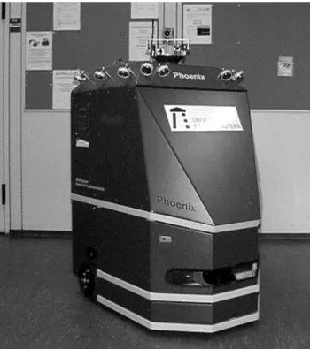
fault tolerance of mobile robot applications by develop-ing adaptive learndevelop-ing techniques. Among others, one central topic is to find answers to the question of how to solve the global localization problem discussed in the previous section. Current research work includes e.g. unsupervised learning algorithms for classification and interpretation of visual information and global localiza-tion algorithms based on the fusion of laserscans and visual data. Other research topics include sensor data processing, control architectures, behaviour-based ap-proaches and life-long learning. Fig. 1 shows our new mobile robot Phoenix which serves as host for our ex-periments. Phoenix is a three-wheeled vehicle with a differential drive. The robot's current sensor configura-tion includes a video camera on a pan/tilt-unit, a sonar sensor system, and a Sick LMS laserscanner. Addtional-ly, Phoenix will be equipped with infrared, sonar, and tactile sensors. The final control structure consists of two standard PC's and a laptop PC running the realtime OS QNX. A wireless ethernet links the robot to the team's workstation domain.
4 BAR CODES
Bar codes are nowadays frequently used in almost all industrial branches whenever an information needs to be read automatically. The great variety of applications led to the existence of approximately 200 different codes which are altogether subsumed under the term bar code. Usually, the term symbology denotes a particular bar code scheme, while the term symbol refers to the bar code label itself [6]. A good example showing that bar codes became a part of everyone's daily life is their use in supermarkets. In Europe, for instance, the Euro-pean Article Numbering (EAN) system is used in order to label consumer goods. Fig. 2a shows an example of an EAN-13 symbol [7].
Bar codes encode information along one dimension with intervals of alternating diffuse reflectivity. The intervals are actually stored as rectangles whose vertical height carries no information but facilitates the scanning pro-cess. The term bars denotes the rectangles with the foreground color while the term spaces denotes the in-tervals with the background color between the bars. Usually, the foreground color is black and the back-ground color is white. Both, bars and spaces are often denoted with the term elements.
Basically, we distinguish between two classes of sym-bologies: delta codes and width codes. Delta codes
subdivide the available interval of a symbol into areas of the same size which are called modules. Each mod-ule is assigned a bit. Modmod-ules with 1's are painted in foreground color and form the bars, while modules with 0's form the spaces. Please note, that a single bar or space may contain many modules. The EAN-13 code
mentioned above (Fig.2a) is an example for a delta code. Width codes assign each bit either to a bar or to a space. Whether a bar/space represents a '1' or a '0' de-pends on its width: Wide elements represent the high bits while narrow elements represent the low bits. Usu-ally, a wide element has twice the width of a narrow element.
Generally, delta codes have the advantage of providing a higher information density. However, in comparison to width codes they are less fault tolerant. Some width codes are called self-checking because they offer the opportunity to immediately detect single errors.
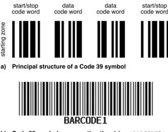
An example for a width code is Code 39 which was used to perform the experiments presented here. Code 39 has a total of nine elements per code word, five of which are bars with four spaces in between. Moreover, three of the nine elements are wide elements. This is where the name comes from. In total, the code can gen-erate 84 individual code words of which, however, only 44 are used for representing the 10 digits, 26 letters, and 8 special symbols (hyphen, period, space, asterisk (*), $,/,+, and %). Please note, that the asterisk is used as the start and stop code word of a symbol, only. The patterns for both, the bars and the spaces have been chosen such that changing a single bit in either of them results in an illegal code word. The fact that bars always have an
Fig. 3: Examples of Code 39 symbols Fig. 2: Example of an EAN-13 bar code label
b) Code 39 symbol, representing the string *BARCODE1*
start/stop code word start/stop code word data code word data code word starting zone
even number of wide elements while spaces always have an odd number allows to immediately detect single errors. Thus, Code 39 is a self-checking code. Code 39 offers the option to include a checksum. If this option is used the checksum is encoded by the penultimate code word. Fig. 3a shows the principal structure of a Code 39 symbol with four code words, while Fig. 3b shows a Code 39 symbol with 10 code words, represent-ing the strrepresent-ing 'BARCODE1'.
Barcodes are read by using specific optical scanning de-vices. These are usually either hand-held or stationary laser scanners. Hand-held scanners are used in such a manner that a human operator searches the bar code la-bel and brings the scanner manually in a position from where the data can be read. In order to prevent misread-ings, this position is ideally right in front of the bar code label at a distance which ensures that the symbol is visi-ble for the scanner, only. If the symbol's surroundings are partially visible for the scanner, misreadings may occur whenever a pattern looking alike a symbol is de-tected. If this happens, the operator has to diminish the distance in order to read the symbol. Hand-held laser scanners are nowadays common at cash registers in su-permarkets. Stationary scanners generally share the common problem that they cover a wider detection area so that the bar code label to be read is one pattern among many others. Consequently, these devices must be able to identify the relevant information by filtering the input data stream. Besides their use in supermarkets stationary scanners are often found in industrial envi-ronments e.g. to gather information about items passing on a conveyor belt.
[6] provides a good introduction into the fundamentals of bar code information theory while a comprehensive description may be found in [5].
5 VISUAL BAR CODE RECOGNITION
AND EXPERIMENTAL RESULTS
Our algorithm for visual bar code recognition is current-ly based on gray scale images provided by the robot's on board video camera. On principle, the algorithm scans the image matrix row by row in order to find Code 39 symbols. Since every bar code label starts per definition with a starting zone, the algorithm searches for a candi-date starting zone, first. If one is found, the algorithm checks whether the subsequent code word is an asterisk. Please recall, that this is the start code word of a Code 39 symbol. In case no asterisk is found, the algorithm continues searching for a starting zone until either an-other starting zone is found or the last pixel of the image has been processed. If, however, an asterisk is found, the algorithm proceeds by reading the remaining code words of the symbol. Obviously, the code wordencod-ing the checksum can not be identified until the stop code word has been read. The symbol is considered to be syntactically correct if the checksum can be verified. Reading the code words of a symbol implies three tests to be performed consecutively for each code word. First of all, it is necessary to check whether or not the speci-fied number of bars is correct. With Code 39, five bars need to be read. Next, there has to be verified whether or not the width of the elements is aligned with the specification, which defines that exactly three elements must be twice as wide as the others. Moreover, at least one of these wide elements must be a bar and at least one of them must be a space. The algorithm finally ac-cepts the code word, if it meets the symbology's specifi-cation.
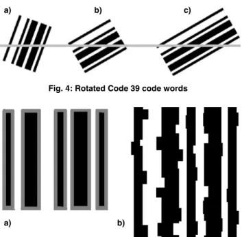
Since the video camera is mounted on a mobile robot, the algorithm is faced with a couple of imponderabili-ties which eventually prevent a symbol from being read. The bar code label may for example be soiled or dam-aged or parts of it may be hidden by another object. Please note, that the latter is a problem only, if not the full width of the symbol is visible for the camera. An-other problem may arise when the symbol has been ro-tated for some reason. If this is the case, it depends on the angle of rotation whether the symbol can be read or not. Fig. 4 examplifies these circumstances. Fig. 4a shows a code word which has been rotated by an angle a1 with respect to the baseline of the image. This code word can be read correctly because the scanline, which is parallel to the image's baseline, intersects both, the code word's left-hand and right-hand side, respectively. Fig. 4b shows the same code word, but rotated by the angle a2 (a2 > a1). Since the scanline intersects the
Fig. 4: Rotated Code 39 code words
a) b) c)
Fig. 5: Examples of quantization errors
code word's top side it is illegible. However, if this sym-bol's height is increased the symbol becomes readable again (Fig. 4c). This example demonstrates that the height of a code word bears redundant information and enhances the readability of a symbol significantly. Let us now consider an arbitrary door in the middle of a hallway which has been furnished with a bar code label additionally to its door plate. While the robot is ap-proaching the door, the label will appear perspectively distorted in the image which aggravates the symbol's recognition. Please note, that this is the normal case and not the exception. Here, the readability of the symbol depends on its size, the viewing angle, the distance be-tween the label and the camera, and some camera pa-rameters such as focus and focal length. Additionally, the quantization as part of the image processing has an impact on the readability of a bar code label. One prob-lem arising here is that high-contrast edges in the origi-nal image normally are converted into medium gray scale values. This effect is shown in Fig. 5a. Pixel errors caused by the quantization process are another problem which may affect the readability of a bar code label. Fig. 5b examplifies these circumstances. Nevertheless, since the height of a label carries redundant information, this problem is not critical in so far as it is likely that the symbol will be encoded while one of the subsequent rows is scanned.
Besides this, the readability of a bar code label is affect-ed by the lighting conditions, since both, brightness and contrast of an image depend on the ambient light. Seen from the perspective of our algorithm, an ideal image has black bars with sharp outlines against a white back-ground. However, this ideal will almost never be reached. Thus, in order to become independent from the lighting conditions, i.e. to obtain information about the brightness of an image, the algorithm computes the mean J of the gray scale values of all pixels, first. J is used as a threshold in the sense that the algorithm sub-sequently considers a pixel to be bright if its gray scale value exceeds J, and black, otherwise.
The fact that it is for any given image a priori unknown whether or not it contains a bar code label offers on principle two contrary strategies of how to perform the search. The first strategy tries to analyse an image as good as possible by alternately searching and filtering the image. This process is continued until either a bar code label has been found or the process exceeds a giv-en time limit. Please note, that depgiv-ending on the proper-ties of a particular environment this strategy is likely to find a bar code label, even if there is none. Let us for example assume that a book shelf which is character-ized by numerous vertical edges is visible in the image. Then, the repeated search-and-filter process will prob-ably extract patterns resembling valid symbols. In con-trast to this approach, the second strategy tries to
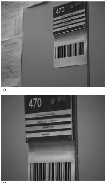
mini-Fig. 7: Examples of a Code 39 symbol consisting of 4 co-de words which could be ico-dentified (String: *C2*). In b), the label is only partially visible.
Fig. 6: This Code 39 symbol was not readable.
a)
mize the computational effort per image by simply as-suming that if an existing bar code label is not recog-nized in an image, it will be found in one of the follow-ing images provided the robot is approachfollow-ing the label. Hence, no additional and time consuming filter mecha-nisms need to be involved. The current implementation of our algorithm applies this strategy.
At this point, the question needs to be answered which kind of information should be stored on a bar code la-bel. Certainly, this depends on the application. Howev-er, two principal possibilities can be identified. Con-cerning the first of them, all information is stored on the bar code label. In the case of Code 39, this leads to comparatively wide symbols which is a problem, if the physical dimensions of the labels are limited by an ap-plication. This is for instance the case in the door-exam-ple mentioned earlier. Our approach utilizes the second possibility. Here, the label stores a code string, only, which must be unique within the robot's environment. This string is used as key for accessing a data base where all relevant information is stored. This informa-tion helps to answer the quesinforma-tion "Where am I?" if it is associated with a global map of the robot's environment. The figures 6-8 present experimental results. Fig. 6 shows a bar code label which could not be identified by our algorithm. In contrast, the symbol presented in Fig. 7a could be identified as well as the only partially visi-ble symbol of Fig. 7b. Fig. 8 presents identification re-sults of a perspectively distorted bar code label consi-sting of 10 code words.
6 CONCLUSIONS
This paper has addressed the self-localization problem which is of central significance for the implementation of autonomous mobile service robots. If the research community wants their mobile robots to leave the labs in order to become really useful in real-world applica-tions under real-world condiapplica-tions, robust and reliable solutions for this problem need to be found. Moreover, if the mobile robots are intended to leave the labs in the not too distant future the required solutions need to be pragmatic.
Against this background the paper presented a pragma-tic idea which utilizes a camera-based bar code recogni-tion technique in order to support mobile robot localiza-tion in indoor environments. When reading a bar code label the robot is provided with semantic information about the label's local environment. If each label is unique within the environment this immediately re-moves all doubts about the robot's position. This is es-pecially helpful in environments which are impover-ished in the sense that unique natural landmarks are lacking. In such environments, humans utilize artificial
References
[1] W. Burgard, D. Fox and S. Thrun, Active Mobile Robot Localization by Entropy Minimization, Proceedings of the 2nd Euromicro Workshop on Advanced Mobile Ro-bots (EUROBOT'97), Brescia, Italy, IEEE CS Press, 1997.
[2] J. Borenstein, H.R. Everett, and L. Feng, Navigating Mo-bile Robots (Wellesley, MA: A K Peters, Ltd., 1996). [3] G. von Wichert, Mobile robot localization using a
self-or-ganized visual environment representation, Robotics and Autonomous Systems, Volume 25, Numbers 3-4, Elsevi-er, November 1998.
[4] G. Wei§, C. Wetzler, and E. von Puttkamer, Keeping Track of Position and Orientation of Moving Indoor Sys-tems by Correlation of Range-Finder Scans, Proceedings of the 1994 International Conference on Intelligent Ro-bots and Systems, IROS '94, Munich, Germany, 1994. [5] M. Pštter, Barcode: EinfŸhrung und Anwendungen
(Hannover, Germany: Heise-Verlag, 1993).
[6] T. Pavlidis, J. Swartz, and P.Y. Wang, Fundamentals of Bar Code Information Theory, IEEE Computer, April 1990.
[7] http://www.adams1.com
Fig. 8: Screen Dump showing a perspectively distorted Code 39 symbol which could be identified. The symbol consists of 10 code words encoding the string *RAUM413B*
landmarks, e.g. door plates, etc., too. In this context, the use of bar codes has advantages over conventional algo-rithms for optical character recognition. One of these advantages is their inherent redundancy. Another one is given by the fact, that they are easier to be detected in an image than alphanumeric labels.
An algorithm which detects and reads Code 39 bar code symbols in video images has been presented together with experimental results.