TÍTOL DEL TFC: BladeDesigner Beta Testing Process & Getting Started Guide TITULACIÓ: Enginyeria Tècnica Aeronàutica, especialitat Aeronavegació AUTOR: Antillach París, Jordi
DIRECTOR: Lang, Sebastian DATA: 8 de juliol de 2011
BladeDesigner Beta Testing
Process & Getting Started Guide
Author:
Antillach París, Jordi
Tutor:
Lang, Sebastian
Start:
01/05/2011
Autor: Antillach París, Jordi Director: Lang, Sebastian Data: 15 de juliol de 2011
Resum
Aquest treball representa la culminació de la feina de molts altres estudiants de la TUM que des de fa ja més de 3 anys han iniciat la construcció d'un programa de CAD per a dissenyar compressors d'ús aeronàutic per a motors d'avió.
L'objectiu principal d'aquest treball era dur a terme el procès de testeig beta del software per tal d'elaborar un informe de viabilitat per a l'entrega al públic general. Aquest procès havia de tenir en compte totes les funcions compreses en el programa així com l'interficie creada per a comunicar-se amb l'usuari. A més també es va estimar necessària la creació d'un manual d'iniciació per a usuaris nous als programa com a complement de la documentació que acompanya el programa.
El mètode de testeig emprat en totes les fases de test han set test de caixa negra. Utilitzant exemples de models 3D coneguts i recreant-los amb el programa per a posteriorment comparar-los i trobar en quins punts el programa introdueix errors i deformacions en la representació o simplement assegurar que les funcions cridades compleixen correctament la funció per a la que han estat dissenyades.
La creació de la guía ha estat quasi inherent al fet d'entrar en contacte amb el programa. A través del descobriment de les funcionalitats i basant-me en la documentació addicional proporcionada per la resta de participants en el projecte he anat redactant cada pas que prenia dins del programa així com una definició precisa de tots els elements de la interficie, resumint-los finalment en una guía en forma de manual pas a pas.
La conclusió final malauradament denota que el programa no està llest per a distribuir-lo al públic ja que les funcions relatives a la construcció de geometria estan incompletes en la seva integració amb la interficie i les funcions de suport o secundàries introdueixen errors i desestabilitzen l'operació del programa. No obstant era una conclusió esperada ja que aquest era el primer cop que es duia a terme un procès de testeig sobre el programa i l'expectativa era trobar els errors que posteriorment hauran de ser corretjits.
Author: Antillach París, Jordi Director: Lang, Sebastian Date: July, 15th 2011
Overview
This essay represent the culminating point of the work carried on by students of TUM university that during the last 3 years have initiated a development process to create a CAD tool to design compressors for aeronautical compressors to use in aircraft engines.
The main objective of this project was to perform a Beta testing process on the software in order to elaborate a release to public viability report. This process had to take into account all functions integrated in the program as well as the interface created to communicate with the user. Additionally it was deemed necessary to create a getting started guide for new user to complement the documentation attached to the program.
The testing method used was based on black box tests. Using already known 3D models and recreating them with BladeDesigner to compare them and then establish which functions of the program induced errors to the process or defects in the models generated.
The creation of the guide has almost been a result of the learning process needed to understand the program to test it. Through the acknowledgement of functionalities and supported by the documentation provided by other team members I've documented every step taken into the program as well as a thorough definition of the interface elements summarizing them in a step by step guide.
Unfortunately the final conclusion points out that the program is not ready for public release. The geometry building functions integrated in the interface are incomplete and the secondary functions introduce errors to the building process and destabilize the proper functionality of the program. Nevertheless this conclusion was expected as this was the first time that BladeDesigner underwent a testing process and the expected result was to find these bugs which will have to be corrected later.
1.Thesis introduction …...11
2.Introduction to the program …...13
2.1.Profile generation ...13 2.2.Blade generation …...15 3.Test process …...19 3.1.Introduction …...19 3.2.v.2010 …...21 3.2.1.Test run 1 …...21 3.2.2.Test run 2 …...23 3.2.3.Test run 3 …...25 3.2.4.Conclusions v2010 …...27 3.3.v.2011 …...29 3.3.1.Test run 4 …...29 3.3.2.Test run 5 …...34 3.3.3.Conclusions v2011 …...42
4.Getting started manual …...44
4.1.The interface …...44
4.1.1. Turbo machine main window …...47
4.1.2. Blade row main window …...49
4.1.3. Profile main window …...53
4.1.4.SCMMesher window …...55
4.2.My first turbo machine …...57
4.3.Export your work …...61
4.4.SCMMesher tutorial …...61 5.Final conclusions …...64 6.Annexes …...67 6.1.Unittest …...68 6.2.Troubleshooting guide …...70 Bibliography …...73
3.1 - Flow chart with the testing procedure …...20
3.2 - Shell error message after attempted save …...33
3.3 - Shell error when importing incorrectly named files …...36
3.4 - Shell error when importing a incorrect type of file …...37
3.5 - Shell error for incorrect Degree values …...38
3.6 - Shell error when CpFt values are not entered …...39
3.7 – Shell error when trying to execute SCMMesher …...40
4.1 - BladeDesigner interface layout …...45
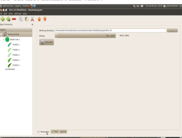
4.2 – Turbo machine Parameters window …...47
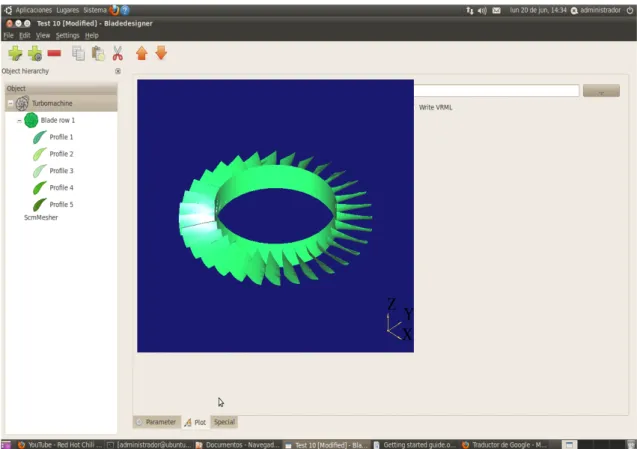
4.3 – Turbo machine Plot window …...48
4.4 – Turbo machine Special window …...49
4.5 - Blade row Parameters window …...50
4.6 - Blade row Plot window …...51
4.7 - Blade row Parameters plot window …...52
4.8 - Blade row Special window …...53
4.9 - Profile Parameters page …...54
4.10 - Profile Plot window …...55
4.1 - Data example for the hub .…... 58
4.2 - Data example for the shroud …...59
4.3 - Data example for the stacking line …...59
4.4 - Example polynomial coefficients …...60
4.5 - Example for the span …...60
4.6 - Example values for the options parameters …...62
4.7 - Example values for the BlockCellsAx …...62
4.8 - Example values for radial parameters …...62
4.9 - Example options for CGNS output choices …...63
4.10 - Example values for the CpFt coefficients …...63
Abbreviations
NURBS Non Rational Uniform Base-Spline CAD Computer Aided Design
CFD Computational Fluid Dynamics
STEP Standard for the Exchange of Product Model Data IGES Initial Graphics Exchange Specification
STL Surface Tesselation Language XML Extensible Markup Language
Variables
γ Stagger angle β1 Angle of attack β2 Exit angle
∆s Edge length of two-dimensional network elements
∆φ Edge length of the three-dimensional network elements in the circumferential direction
∆ψ Translation compensation in the circumferential direction zyl Vector in cylindrical coordinates
kart Vector in cartesian coordinates D (x) Thickness distribution
Dmax Maximum thickness
K Number of network elements / element edges in the meridional direction L Number of network elements / element edges in the circumferential
direction
p0, ... , p3, coefficients for polynomial thickness distribution b0, ... , b4 coefficients for polynomial thickness distribution 2D Two-dimensional vector
3D Three-dimensional vector
h Running index for nodes in the circumferential direction m, y' Two-dimensional space into rotation coordinates area-related r, φ, z Three-dimensional space in cylindrical coordinates
x, y, z Three-dimensional space in cartesian coordinates g Running index for node in meridian direction
Chapter 1:
Thesis introduction
It is widely known that one of the most critical parts in any plane it's the engines. The engines are also the component of an aircraft that determine the operational costs of it. The more efficient the less fuel it's needed to cover same distances. So to build a good plane, good engines are needed and by good we mean safe and economically viable. As modern turbofan and turbojet engines rely on thermodynamic cycles to obtain propulsion energy from the power of the air mass flow going through them it's important to meet the performance parameters needed to get the maximum efficiency while ensuring they provide enough power to keep the plane flying. The adequate pressure at the entry of the combustion chamber it's the key to make all the engine work and for that compressors are needed. A compressor is usually formed by several fans spinning at different speeds and stacked in cascade their main function is to increase the air's pressure as it passes through their blades. So as important it is to have good airfoils to ensure aircraft's lift, the adequate shape of the blade in the compressor allows the adequate pressure to be met.
Nowadays there are many CAD programs that help engineers design the shapes of the future engines and compressors and these 3D models are used in CFD simulators to help engineers correct and perfect these blades. But so far all these CAD programs are generic and can serve multiple purposes. BladeDesigner3D is a program specifically oriented to design 3D models of turbo machines and compressors with aims to provide testing samples for CFD simulators. BladeDesigner is a free software tool developed in the TUM by and for students. BladeDesigner is still a work in progress started a few years ago which required the collaboration of many students and teachers but as a free software licensed program anyone can use and collaborate in improving it.
BladeDesigner is a program based on python scripts but as the most common of the people are not versed in programming and working with shells and command lines BladeDesigner also integrates a Graphic User Interface developed to adapt the program to widespread public use. The program used different calculating methods to build a 3D geometry from the input the user feeds so there's no actual need from the user to define the geometry the program interprets the data to build the geometry desired. Using any method the program work in tree scheme. The turbo machine is the final element desired and it's composed of the different blade rows and each blade rows is composed of multiple blade defined using airfoil profile that conform a single blade. This way the user controls each step of the process from the smallest element to the final geometry. As the final purpose of the program is to create valid geometry to use in CFD testing the program also has built in special functions to export these geometries into compatible file formats for the most of the actual simulators.
Currently the last version released from BladeDesigner is a Beta version which means it's intended to be fully functional in all aspects but that hasn't been tested. Testing is critical for the success of any software in any market because it ensures that the product
delivered to the public is free of errors and that people will be able to use as it is explained in the manual. Assuming that the users of the program don't need any skills in programming a bugged version of the program will cause the users to be unable to operate the program and thus rendering all the work useless.
Beta testing is an important part of the quality process of any software. It's intended to explore all functions of the program and check their correct response in all possible situations given by the user. It is in fact a simulation of what the final user may encounter when faced with the program.
Generally software developers have several people testing the same version of the program at the same time to ensure that all kinds of possibilities are covered but as BladeDesigner is a small project there's only one Beta tester. The following study is the Beta testing process followed with the two latest versions of BladeDesigner. In it all functions and processes of the BladeDesigner software have been tested in all situations possible with all the variations available. The conclusions are a compendium of all bugs encountered, under which circumstances and the probable agents that caused them. All this information is summarized to provide the developers with accuracy which functions have to be modified or redesigned, which parts of the program aren't working and an overall perspective of the readiness status of the program for public release.
Another important goal of this study as the first Beta testing process done to BladeDesigner program is to provide a guideline for future testing procedures and also a checkpoint of the actual state of the program. As new versions are released this document has to be updated to the new versions and results have to be compared to check if progress is made in the right directions removing old bugs and not creating new ones.
This was also the first time that a student not related to the creation process was involved in the project and so his knowledge of the tool was null. This provided the perfect opportunity to create a guide on how to operate the program properly. This manual included within the program will transform BladeDesigner into a complete package of software ready to be released to people without need to train them in the use of the program previously. This guide was created while learning how to use the program so it's oriented to first time users to understand all the aspects of the software and how to use them for their own purposes.
The software and all information about BladeDesigner as well as contact data with the developers and on line help can be found open to the public in: http://sourceforge.net/projects/bladedesigner/
Chapter 2:
Introduction to BladeDesigner
BladeDesigner 3D is a CAD program designer to build geometry of turbo machines The process that lead to geometry generation is rather complex and involves a series of calculations and plane interpolations which are built inside the program to facilitate the users work. In order to fully understand the functionality of the program and the reasons for all the data that it asks it's necessary to know these internal processes.
The design process starts by calculating the thermal and aerodynamic parameters of the the turbo machine we want to implement. These data will provide us the information we need to determine the entry and exit angles and cross sections that the air flow must go through to match the calculations done for the inlet and outlet of the turbo machine These angles and cross sections are the data that we'll need to generate the 2D profiles that will form our blades.
2.1 – Profile generation
This is the actual point where BladeDesigner starts working. Once the user has the data on the leading an trailing edge and the chord the profiles have to be drawn. First step is to discretize the profiles and allocate the points that will form the skeleton line along the one dimensional chord. To that purpose BladeDesigner uses a finite difference method, the tridiagonal matrix algorithm (TDMA). These method provides the program with the control points where the thickness distribution is going to be developed along the chord line. These methods are fully explained in [2] of the Bibliography.
To ensure a proper thickness distribution the allocation of points of the TDMA is combined with weighting functions. The weighting functions control the matrix algorithm and thus have also the control of the final control points. Each profiles needs an adapted distribution to achieve a trustful representation. Thus the program has implemented several different types of weighting functions which the user can change depending on the needs of each profile.
The basic method uses the curvature of the chord contour as guideline for weighting. This method shows good results but for profiles with high curvature is not enough as this method procures an evenly distribution. For profiles with high curvature around the leading or trailing edge the resolution is not enough. That why the contour method can be combined with weighting functions to maximize it's effectiveness. These functions include different types of conditions that can be switched to better match the needs of the current profile. Arc sine, tangent, hyperbola, cubic parabola, parabola and straight line are the conditions available for the weighting functions. These weighting functions can be combined with the basic method or used to substitute it if it better suits the accuracy of the final construction.
The weighted skeleton line points distributed will be the coordinates where the thickness functions will be applied. There are three methods to apply the thickness distribution to a profile.
– Power function
– NACA 65
– Elliptic
The power function methods is formed by these two functions:
The first functions once assigned the correspondent parameters p and b and given x which is the vector of points in the camber line assigned previously it returns the list of values of the thickness distribution.
The second function generates the radius for the nose of the leading and trailing edges. The derivative for x of this function:
Establishes the contour for the thickness distribution
The NACA 65 method uses a standard NACA thickness distribution approximation The input data needed is the x-vector containing the point from the weighted distribution in the chamber line and a value for maximum profile thickness. Using the standard defined function:
The returned value is a list of values for thickness distribution along the points defined (2.1)
(2.2)
(2.3)
for the weighting methods.
The elliptic thickness distribution method uses the general form of the ellipse:
and combines these conditions:
to get this function:
Which once established a value for the maximum thickness Dmax and given the x-vector of point distribution, the output of the functions is a the list of values for thickness distribution along the camber line points.
2.2 – Blade Generation
Once the profiles have been created the next step is to create the blades that will form the blade row. For a more thorough explanations on the following look [1] in the
Bibliography. The idea behind is that each blade is formed by profile sections aligned in space. The profiles exist as a set of coordinates in a 2D space that can be place inside a 3D space without need to interpolate them. Thanks to this feature the only errors introduced in the process are mapping errors and not interpolation errors.
Previous steps to map the 3D surfaces of the blade are necessary to adapt the 2D profiles for use:
– Scaling of the profiles (determine absolute size)
– Rotation/Translation of the profiles (placement in space)
– Determination of the juncture point between the blade and the central ring
– Geometry of the central ring
The scaling of the profiles is determined by the chord length specifies in each one. All the profiles forming a blade are linked between them by a line intersecting them in their
(2.5)
(2.6)
center of mass which is called the stacking line. This line joins all the profiles in a single element and establishes the translation parameter for correct placement in space. The stagger angle of each profile establishes their rotation around the stacking line giving them the correct orientation in space. The juncture point or stacking point is defined by the placement of the first profile in space. The central ring geometry is user defined in the program.
The algorithms used to define all these parameters above is different depending on which type of turbo machine we want to create. The methods for an axial compressor will be different from the ones for a radial compressor.
With the coordinates for the profiles placement calculated the next step is to perform the mapping of the 3D surfaces. When dealing with 3D surfaces mapping distortion of the geometry is a common problem. BladeDesigner integrates two mapping methods to avoid this problem: the angle preserving method or the length preserving method.
In the length preserving method each profile coordinate point is transformed during the rotation and translation method to the 3D coordinate space using the following function:
In this case the cylindrical surface of revolution is an isometric figure which also preserves the angles so no distortion is introduced in the process.
For the angle preserving method the goal is to achieve an angle conforming mapping of the 2D profiles. The complexity of the problem comes from the nature of the profiles which exist as a cloud of points. The solution is based on a networked surface shaped like a mesh that will be mapped over. This process is accomplished in five steps.
First step is positioning the profile. The 2D cloud of points must be transformed into a 3D space using the function:
Second step is to generate a 2D network suitable for meshing. Using the profile points a (2.8)
2D grid is defined. The number of cells is given by the function:
and the size of the cells is given by the function:
Third step is generating a 3D mesh from the 2D grid. To meet on a double curved surface of revolution the cell size must determined by the function:
The properties of the imaging network are essential for the quality of conformal mapping because depending on the values of the parameters Δφ more or less severely distorted lengths can be shown. The correct numerical solution for this parameter comes form the function:
Now the 3D coordinates of the nodes are calculated using the following function: (2.10)
(2.11)
(2.12)
(2.013)
Fourth step is to indexate the coordinates. For this task we need to determines 4 component of each point using the functions:
Fifth and last step is to map the 3D grid. The profile coordinates in r, φ, z-space need to be translated into a z, y, l-space with the following function:
Now the profiles are in cylindrical coordinates but with the transformation matrix:
can be transformed into cartesian coordinates which can be mapped in 3D.
To create a whole turbo machine the process is repeated as many times as blade rows the user has specified switching the coordinates following the users parameters to create a full turbo machine geometry.
(2.15)
(2.16)
(2.17)
Chapter 3:
Test process
3.1 – Introduction to the test process
Before starting any testing it was necessary to design the testing procedure as this was the first time this was done on BladeDesigner. Having a defined test procedure is important because it defines the strategy to follow during the test and more important even it gives an example on how to realize further testing with other versions of the program. Moreover by repeating the same procedure after introducing changes in the code the developers can be sure that the bugs previously encountered are being solved. The test procedure had to include every aspect of the program to be thorough and complete. It was designed to test every aspect prioritizing the critical aspects of the program like the building functions that are considered the cornerstone of the program as without these functions the rest are useless and the whole program is left without purpose. But as important as the correct operation of the functions is the readiness of the GUI as even is the functions are working properly on code it's integration with the buttons of the visual interface can introduce errors to the procedure. So with this goal the testing procedure was divided in two aspects: interface and functionalities.
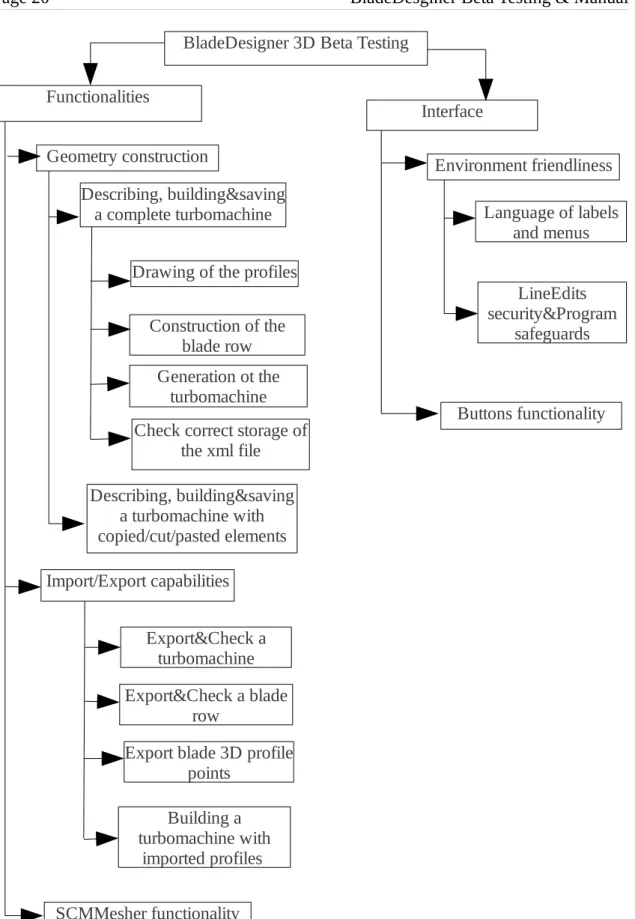
During the test procedure some bugs indicated the probability of further errors combining program options which hadn't been included at first on the testing schedule so the actual version of the testing procedure it's a revised version. You can see the latest version on Figure 3.1. Eventually the test procedure was perfected while during the tests as new glitches and other probabilities of error were discovered. All the testing procedure can be summarized in the following flow chart which explains the steps taken during the testing in descending order of criticality for the program.
BladeDesigner 3D Beta Testing Interface Functionalities Environment friendliness LineEdits security&Program safeguards Language of labels and menus Buttons functionality Geometry construction Describing, building&saving a complete turbomachine
Drawing of the profiles Construction of the
blade row Generation ot the
turbomachine Check correct storage of
the xml file Describing, building&saving a turbomachine with copied/cut/pasted elements Import/Export capabilities Export&Check a turbomachine Export&Check a blade row Building a turbomachine with imported profiles Export blade 3D profile
points
SCMMesher functionality
Figure 3.1 – Flow chart with the testing
3.2 – Test runs on the 2010 version
The following pages contain the test reports written as result of the testing process on the 2010 version of BladeDesigner. Each report summarizes the tests runs made.
3.2.1 - Test Report #1: Getting started&Interface Testing
This first test is oriented to explore the limits and safeguards of the bladedesigner program against a new user with no knowledge of the code and only with the help of the BladeDesigner pdf document and a turbo machine example already done. This test belongs to the interface testing branch of the testing procedure. The objects under testing will be:
– Environment friendliness
– Line edits safeguards (against mis-entries, overload numbers, etc...)
– Proper functionality of all buttons
– Accuracy of the guide provided.
Object 1 – Environment friendliness
When first opening the program the GUI welcomes you with an already set turbo machine with one blade row and and one profile with parameters set to 0. This helps the user get started right away without searching any menus. The left-hand-side cascade distribution helps the user organize all blade rows and profiles at any time, differentiating them by number and color The labels are correctly linked to the line edits so the user knows at every time what inputs is he giving. The tool bar gives easy and quick access to most common operations. Menu bar is simple and uses common terminology like in common Linux/Windows applications thus making it easier for the user to interact. All in all the GUI is friendly for first time users and easy to learn and use.
For non-German users it's possible to switch the language setting to English in the Settings menu tab. The translation is accurate in general minding some minor spelling mistakes and all the aspects of the program have been translated without mixing languages in any page.
A minor issue detected is that when trying to save the project for further study the program doesn't send an OK message confirming the action has been performed correctly. It does not affect the proper functionality of the program but it's an easy procedure that assures the user in all the steps he's taking. It does check if you want to safe after closing or opening a new turbo machine which is good.
Object 2 – Line edits safeguards
To this matter line edits have been tested by trying to enter letters or impossible numbers as input values. For this purpose we've tried all the line edits in all the program (turbo machine/blade row/profile pages) and with all the method options available. The
testing method is simple: type words or symbols and try to operate the program. The program auto detects the letters and symbols different from +/- and is not possible to write them. As for overloaded numbers it's possible to enter them but when trying to calculate the program sends a warning informing about overloaded inputs and in which field they're located. This is a good and sufficient safeguard protocol for this kind of program.
Object 3 – Button functionality
In this test we used the turbo machine example to test only the proper functionality of the buttons without looking into the functions performance. To this matter the buttons in the tool bar, the menu options and the Calculate buttons in the blade row and turbo machine were part of the test.
First testing the menu bar all the options available operated on command as expected. All th options are fully functional. The tool bar buttons also operate correctly performing all the operations commanded on click. Both calculate buttons are well linked to their respective functions and initiate it's intended operations when clicked. So far this test indicates that all buttons in the program are well integrated to their respective functions in the code.
Object 4 – Guide's accuracy
The provided pdf guide offers an insight on the physics which the program uses to do it's calculations and a step by step guide to create a turbo machine with a rotor and a stator rows. The guide offers guidance to introduce the parameters to the input labels to reach a result properly. A major problem detected in the guide is that is based on a polynomial function for the profiles but inside the program there's is no such option for polynomial function (just power function, circular arc and Nurbs). This confuses the user and forces him to improvise which will surely lead to many errors and frustration of the user. Some relevant input data (like chord thickness) isn't defined through the guide and it needs to be guessed based on the pictures of examples This adds more confusion to the user who cannot be sure if it's doing the correct thing.
Conclusions
This first report has shown that the program's interface is well implemented and translated. In general it suits it's purpose (help the user interact with the code behind it) and works correctly in every aspect. Although this test shows that all buttons and menu options perform correctly their respective operations they have been tested separately without combining their use. This combined testing falls under the testing branch of functionalities.
3.2.2 - Test Report #2: Working with examples
This second test is the first test of the functionalities branch of the testing procedure. This test is prepared to test the program when attempting to build geometry. For this purpose I will be using the turbo machine example given by the tutor. Objects under testing will be:
– Creating a simple turbo machine
– Copying/Cutting/Pasting profiles and blade rows Object 1 – Changing data on a existing sample
The first attempt of testing was to create a turbo machine from scratch using the instructions in the pdf manual. This was the first time during the testing procedure to create an original turbo machine not taken from examples. First issue detected in this test was the lack of a calculate button in the profile's parameters page. As result of this profiles aren't drawn and the rest of the operation cannot continue. The blade row's Calculate button doesn't activate the process and appears to be deactivated while in previous testing it showed a normal operation. Turbo machine's calculate buttons show the same behavior No attempt of profile generation was successful and further testing proved impossible by the inability to generate any geometry.
With a set example the user is able to override the lack of a calculate button for the profiles as the program automatically reacts to the new entered numbers and changes the shape of the existing profiles. That way and after several tries the program presented a coherent functionality and showed good results. Geometry for the blade row and turbo machine was created as in normal operation and the files were stored correctly. Only problem detected after over 10 different tries is related to the error messaging.
When entered some incoherent data between profiles the program warns you with a message box: “Fehler list index out of range”. This message is unclear of the error source and deactivates the calculate button until data is changed. By changing data meaning that any kind of change is prone to reactivate the button and of course if the change does not involve the source of error giving again the same message box The uncertainty pinpointing the source of the error is not a program error itself but it's an issue when trying to correct the data as the user if forced to check all data entered and search visually for the mistake.
Another incoherency detected in the program is about construction levels. The problems comes out when changing levels of action. When using high value date (in the case provided 170º for angle of attack) in the profiles the blade row is built normally. The 3D presentation is coherent with the data and the program issues no warning. Then the entire turbo machine is built and although the progress bar acts as normally when it reaches 100% and the user checks the plot it realizes that the figure given is not the expected (in fact it's still the same figure from before changing the values). When trying to repeat the process without changing the data the blade row construction now fails issuing the Fehler warning. I'm not sure where the problem comes from as for all the
tries made the blade row is built with no problems initially but after the turbo machine construction gives buggy results the second attempt to build the same blade row fails in all cases tried.
Object 2 – Copying/Cutting/Pasting blades and profile rows
After a fast set of testing we've been able to identify copy/paste options a source for major glitches. First thing noticed was that when using the feature to copy/paste both profiles or blade rows is that it causes a major glitch in the turbo machine's “calculate” button. In fact whenever the user tries to build a turbo machines containing copied and pasted elements he finds that the button is deactivated and unable to use it. The effect then is terminating for the programs operation has it cancels it's last function. The program is able to build and present blade rows coherent with the data given and the new copied profiles but when trying to finish the construction by creating a turbo machine it fails in all conditions tried (single blade row with copied profiles, multiple copied blade rows, multiple original blade rows with copied profiles in them).
The other fatal glitch caused by the copy/paste functions is related to saving. Whenever a turbo machines containing copied elements (profiles or blade rows) is saved, the save fails as when the user tries to open it after working on a different profile the program opens a new turbo machine When checking the storage folder looking for the file with copied elements the user realizes it has never been saved and therefore is lost. The effect is directly related because after saving a file with copied and then saved another one without them the first is lost but the second one is saved normally. Even a previously saved turbo machine when reopened and added some copied element is deleted from the folder where it was correctly stored.
Conclusions
After this second battery of testing one major glitch has been detected. The problems arisen by the copy/paste functionalities are a major setback for the program as they affect directly the normal functioning of itself. By disabling the construction process of the turbo machines and disabling the save function of the program they rend it useless. The incoherences problems detected with the first object tests, although important because they affect the functionality of the program, are less critic as they appear only for some values very close to the program's margin of operation which aren't really used in actual turbo machines parameters Still the program's inability to pinpoint more accurately the source of the problem is an issue which directly affects the interaction of the user with the software.
3.2.3 - Test Report #3: Other analysis methods
So far all testing procedure have been performed using the “power function” option for the camber line and thickness distribution. This third test is oriented to work with the other options and verify if the bugs found so far are consistent with all the other methods provided by the program. This is an extension to the previous test and so it falls under the category of functionality testing inside the testing scheme. To this purpose we will use the turboexample [4] and change it to suit the test. The objects under test will be:
– Test runs without combining methods
– Test runs combining methods
Object 1 – Test runs without combining methods
This first test run was oriented to test aspects from already tested in the test series #2 but using alternate methods for the chord and thickness distribution. As seen on test report 1 the inability to calculate a profile plot forces the user to use a already done example (turboexample in our case) and work by changing that example. Problems arisen during this test phase relate to this issue. While changing the base method of chord and thickness distribution the program resets the plot leaving the user without the capability to build a new plot and thus preventing further testing. The only exception is the Nurbs method which accepts changes from an already built profile without erasing it. Tests under this option have been consistent with the issues presented in test reports 1 and 2. The same functionality problems as described previously were found when using the copy/cut/paste function. This can lead to the conclusion that the bug with these functions affects in general all the other options of the program with a lot of certainty. Even so until all the calculation methods can be tested there is no way to check if this statement is true.
As for the method use itself I have to point out that this is the first time using the program options without a step-by-step guide. The documentation provided is very thorough with the power function method but with the other methods it's very theoretical and without examples. The user feels the need for a more complete guide to acquire good results. The geometry built is quite complex and small disagreements within the profiles can easily cause the final geometry to be impossible to build. Without proper guidance and error managing the user can find himself trapped in an error loop.
Object 2 – Test runs combining methods
Given the issues presented above the only combined methods able for using were the Nurbs method combined with the power function Using this two methods for creating combined profiles the user is able to successfully build a blade row and the consequent turbo machine Interaction between methods is well implemented and the program raises the proper warnings whenever the constructions is not possible due to incoherences between profiles.
Again the same error pattern was repeated when using the copy/cut/paste functions. Leaving aside these issue we can determine that at least the two methods tested combine each other correctly and the safest guess is that the integration between methods is well implemented and won't affect the proper construction of the geometry. Yet again the conclusion cannot be truly confirmed until there's a possibility to check all the methods available in the program.
Conclusions
Though more was expected from this test the inability to successfully build profiles with the NACA 65 and double circular arc methods proved to be a drag to this test runs. This problem was already found in test runs #2 but overrode by using the [4] as an initial point to introduce changes. The program self starting protocol when changing methods rules out this possibility for the two methods mentioned above but not for the Nurbs method. This exception allowed some amount of testing though it also points out that the code is not coherent for all methods. This differences don't affect the normal operation of the program and haven't arisen any bugs or errors though. The test that we were able to perform showed consistency with the previous tests and confirm the bugs discovered so far (mainly the inability to create profiles and the malfunction of the save and build options when working with copied and pasted elements). This test runs also was the first approach to the different methods contained within the program. Although this is not related to the program itself the tester has to point out that the documentation given to work with the program is very scarce related to this methods and proves the program to be very hard to work for non experienced users. It is strongly suggested to create new documentation including a thorough explanation of these methods in order to help the user interact with the program more easily.
3.2.4 - Conclusions on the 2010 version
Once concluded the testing process for the 2010 version of BladeDesigner 3D we have to summarize the results and report the actual state of the program regarding readiness for public use. Starting from the most to the least critical bugs and errors encountered in this version from it's functionality point of view the following need to be taken into account.
The most critical part of the program is the geometry buildup that's the whole purpose of the program. In this way the inability to draw new profiles inside the program supposes the most critical bug encountered in this version. The whole process is impossible to be completed without the smallest elements in the chain thus rendering the program useless. Using pre-made examples the program showed however a normal operation and full functionality. This suggests that this critical problem may be solved easily by placing a calculate button in the profile's page to trigger the function to draw the profiles just like in the blade row or the turbo machine
The next bug encountered is the malfunction caused by the copy/cut/paste functions of the program. We've concluded that the use of these function has a corrupting effect only on the XML file containing the turbo machine by deleting it as in cases where the geometry had already been built prior to introducing copied elements the geometry folder and it's documents present in the same folder as the main XML file was not affected at all. The copy/cut/paste options also affect the proper functionality of the program by disabling the calculate buttons and thus making geometry construction impossible. This issue is less critical as although it affects the core of the program's purpose can be avoided by simply not using those functions.
The bug detected when using data values close the program's operating margins affects the construction of the turbo machine because it escapes the safeguards implemented for user data entries. Although they directly affect the operations of the program it's an issue that can be solved easily by recalculating the data entry margin for the parameters of blade rows and profiles without need of any code change.
As for the interface bug report we have to conclude that the GUI introduces no errors from itself into the proper functionality of the program and everything works as it is supposed to when tested separately. All the problems encountered so far are caused by functions mis-integration inside the overall program. The most accurate conclusion is that the GUI will function properly as long as the bugs encountered in the functions programming are fixed.
In overall shape we regrettably have to admit that the program as it is now it's not ready for public use. The first issue presented cuts half of the calculating methods out of operation and forces the user to work with preset examples making him unable to create original work of his own. If we add the bugs introduced by the functions supposed to ease the construction (copy/cut/paste) and force the user to spend more time over a project that could be done simply we find that the program as it is isn't much of a help but an obstacle to the actual work of the user. Also taking into account the bugs arisen from overloaded data values the conclusion is that only a user with accurate data or
expertise in the topic would be able to use the program. The intent of the program isn't that really but to have an easy and accessible to all publics tool to design turbo machines The final conclusion is that this version of the program is still not ready for public release.
3.3 – Test runs on the 2011 version
The following reports correspond to the test series realized on the 2011 version of the program.
3.3.1 - Test Report #4: Testing updated version
In this test I've just installed the newest version of the program which includes some modifications in the visual aspect as well as some additions in representations of the plots. The functionalities remain the same except the new additions and it is our goal to determine if this new version has corrected the bugs encountered so far in the previous version. As now we already have a testing procedure established we'll use it with aims to determine which improvements have been made since the last versions in matter of bugs. The new functionalities also had to be tested and meant a modification of the testing procedure to adapt it to them. The objects under test will be:
– Environment friendliness
– Comparison of functionalities between versions
– Study of the known previous bugs Object 1 – Environment friendliness
Just as done in test 1 the first approach to a program is to determine if a new user with no previous knowledge could get his way around the program. Although the symbols and buttons have been changed and have a new appearance it's functionality remains the same so the same conclusion as test 1 still applies. There are new features such as new plot options and the export options which will be dealt with in the next test report. The idea of including a Manual in the program though it's still under work I guess it's excellent and will prove the ultimate step in creating a product able to be distributed without any need for user preparation or creation of additional documentation to complement the program for user readiness.
As for error protection the line edits have been re-tested under the same conditions as in test 1. It has been tried to enter either letters or symbols in all of the line edits to test the possibility of allowing the user to make a mistake. All line edits allow only entering one symbol (+/-) per line and numbers. Expected as this was already shown in the previous version of the program the program prevents the user from entering data which could cause error when passing the variables through the code.
Down through the hierarchy we repeated the same test with the parameter's page for the profiles. All line edit were tested against user mis-entries and the results were coherent with those obtained for the blade row parameter page. Only + and – symbols are allowed to be entered and numbers. This blockade helps careless users avoid simple mis-entry mistakes which result in errors and loss of work time. Result were coherent with all the possible options of calculation methods..
Object 2 – Comparison of functionalities between versions
This new version has the same functionalities as the older version plus some additions that will be studied in the next test run. Starting with the tool bar the buttons for adding a new profile, adding a new blade row and deleting items work properly and give no problems. This was already confirmed in the older version and is coherent that results stay that way. Profiles and blade rows are created and deleted correctly in new documents and existent document reopened.
Copy, Paste and Cut are also present in this version. Again testing over new turbo machines and existent ones reopened profiles are copied and cut normally and pasted correctly without losing or corrupting the data stored in them. However when copying or cutting entire blade rows the pasted element is corrupted. Either by performing one of those actions the original element remains the same (except when cutting because it's deleted) but the pasted elements based on the original though they maintain the blade row's parameters data have their inside profiles corrupted. When clicking those profiles contained within copied or cut blade rows the page remains blank without showing any of the labels or line edits supposed to contain and this profiles disable the use of the tool bar buttons on them. It's not possible to delete them nor add new profiles to the affected blade row. It's also not possible to copy or cut them neither moving them up or down. This although it shouldn't affect the overall operation of the program means that when creating complex turbo machines with several blade rows which may be very similar between them the user is unable to work on copies of the original blade row forcing him to take more time to create new blade rows and having to enter the data on all of them. Final block of the tool bar are the up and down buttons. This buttons are used to change the order of either profiles or blade rows inside the turbo machines hierarchy allowing the user to change the disposition of the turbo machine without having to delete the existent elements and having to create them again. For blade rows the buttons work perfectly. This has been tested with combinations of up to 5 blade rows in the turbo machine hierarchy. In all the cases the user was able to move any of the elements in any direction wished. For profiles the same was tested with up to 5 profiles inside a blade row. In this case the performance of the Up button was perfect allowing to move any profile desired upwards the hierarchy but the Down button seemed disabled. For any position in the hierarchy tried with profiles the down button didn't performed it's function as if the button was disabled. This didn't cause any crash on the code and has no impact on the programs main functions and is merely a disturbance when working but shows that the inside code differs from it's use in blade rows and profiles when the action performed is the same (inside coding it just means to move an object of any kind) which means that either the code is not well implemented or that there are two different functions depending on the object desired to move and one of them is failing. This kind of redundancy may cause problems elsewhere.
Functions in the menu stay the same with the addition of the Manual. In the Help tab both options open the respective windows correctly. The Manual is empty but that's not a problem of coding it just means that it needs to be written. Language setting work properly and for every window down the hierarchy (turbo machine, blade row and
profile) and every tab in every window (parameters and special, plot do not contain labels which need to be translated) the language switches correctly. View tab allows the user to pop up or down the tool bar and the hierarchy perfectly ant the python shell option also works properly. Edit commands are the same as in the tool bar and when tried to interact to see differences between both none was discovered. The buttons in the Edit menu respond the same as in the tool bar arising the same exceptions and bugs. In the File tab commands New an Close perform its function correctly creating new turbo machines with one blade row containing one profile with blank parameters and closing the program as commanded correctly. Function Open, Save and Save as involved a major bug with the previous version and so are going to be thoroughly tested in the next test object.
Object 3 – Study of known previous bugs
In the test reports from the older version a couple of critical bugs were identified which affected severely the proper functionality of the program. We have to determine if this bugs have been corrected in the new version.
The first bug was related to the functions Copy, Cut and Paste. As seen in the older version working with copied or cut and pasted elements (both profiles and blade rows) the calculate buttons in both blade rows and turbo machines were disabled preventing the user to create the geometry. As the purpose of the program is to create this geometry this bug disables the whole program and is a critical glitch. In the new version we've several scenarios involving this functions. First only copied profiles we're tested. Using two original profiles with data from the documentation we copied one and pasted it and cut the other and pasted it. When trying to create the geometry result was the same as in the older version, both buttons acted as disabled and the program was unresponsive. We tried again only with one copied profile and again with only one cut element. In both cases result was the disabling of the calculate buttons. Then we tested the same but with blade rows. Using two original blade rows containing only one original profile each we used the same method as with profiles. First combining one copied and pasted and once cut and pasted blade rows. In this case blade rows were able to be created normally and the geometry generated was correct but when proceeding to create the turbo machine the button was disabled as in the other cases. We followed trying only with one copied blade row and then with only one cut blade row. Result was consistent with the first try, blade rows were created as in normal operation but the turbo machine's calculate button was disabled. Then we repeated all the process but working with copied elements from different files copying or cutting them from a known working turbo machine and pasting them in a new one for the purpose of test. Results again showed that the calculate buttons were disabled in all cases. This has led to the theory that the copy and cut functions move the bug up the hierarchy because when copying profiles both the blade row and turbo machine calculate button were disabled but when copying blade rows we were able to create the geometry but the turbo machine calculate button was disabled.
The second bug was also related to the Copy and Cut functions and the Save functions. It was discovered that when dealing with turbo machines containing pasted elements the
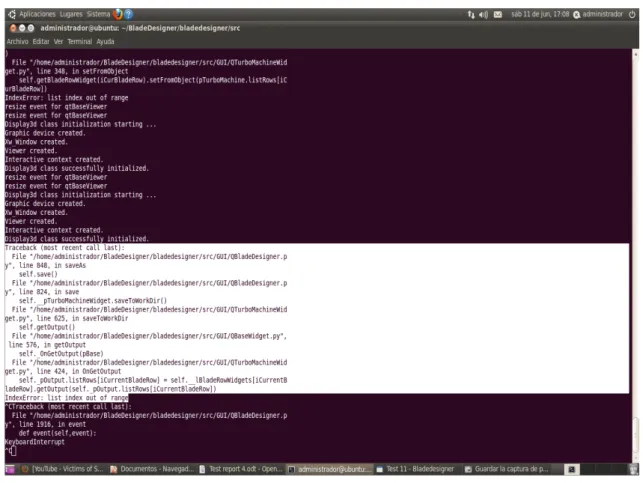
save function was corrupted. The result was not only that the turbo machines wasn't saved but that if already stored in the hard drive and then reopened to add a copied element when attempting to save the XML document was deleted. To test this in the new version we've used the turboexample given in the documentation [4] and saved it in another folder as backup version. With this version we've tried to save it again changing only data in the parameters without copying anything. This way the altered version of the example was saved without problems and was available to access correctly later on. The we reopened the backup version and added a copied profile. Using first only the Save function the result was that the XML file was deleted and when attempted to open the program automatically started a new turbo machine without data. We repeated this test this time using the Save as function and the result was the same, XML file was lost. We repeated both tests using copied elements from different turbo machines than the one we were trying to save and the result was the same. This behavior gave us an idea and we tried a different test. Using only original profiles we used the hot keys combinations Ctrl+c and Ctrl+v to copy and paste only data from the line edits. The results were ambiguous. When using this combination and attempting to save without building the geometry the result was the same as if we had copied elements inside the turbo machine thus deleting the XML file and losing the turbo machines But when using this hot keys combinations to copy data and then building the geometry prior to saving the function worked normally the XML file was saved correctly and was able to be accessed later on. In this case building the geometry prior to saving allowed us to avoid this bug and returned the program to it's nominal way of working. Unfortunately this hot keys don't work with elements from the hierarchy tree so this partial fix isn't useful the solve the prior bug. Looking at the shell we see the feedback from Figure 3.2 when a failed save occurs:
Figure 3.2 – Shell error message after attempted save
Conclusions
After extensively testing this new version we have to conclude that it hasn't solved much problems. We have to consider that this version was released before the beta testing process began so the developers weren't aware of the bugs present and the purpose of this new version was to add more functionalities to the program. The two major bugs spotted in the first test runs are still present in this new version and will have to be dealt with if the program is to reach it's full potential. There are also some new minor glitches that don't affect the proper function of the program (Object 2) but were not present in the older version which suggests that the new functions added to the program might have created some incompatibilities with those functions. This suggests a revision of the new implementation in order to achieve at least the same level of program stability as in the older version.
3.3.2 - Test Report #5: New functions v.2011
This is the last test report for the BladeDesginer software. In this test the objective is to test the new functions added in the 2011 version of the program. These new functions include the export/import features and the SCMMesher. As the whole purpose of the program is to create geometry that will be used later in CFD simulators the program would not be complete without the capability to translate the objects created into a file format compatible with these programs. Some programs are able to create their own meshing schemes based on a geometry given that's why BladeDesigner has the export capability for geometry. Other programs need an already designed mesh to work on and this is why there's also the SCMMesher tool which creates this mesh in a compatible file format for CFD simulators. The tests were run over a previously done turbo machine saved and stored from other tests. The program used to verify the exports was SolidEdge which has import capability for IGES, STEP and STL file formats. This test will cover the two last items of the functionalities branch in the testing scheme which were added when this new version of the program was released. The objects under test in this report will be:
– Import/Export capabilities
– SCMMesher functionality Object 1 – Import/Export capabilities
The import/export capabilities are stored in the tab named Special and only available for blade rows and turbo machines as they are the only objects built in 3D. When a geometry is built in BladeDesigner the resulting object is saved in a folder named geometry inside the folder containing the file and with .XML file format. Now the common file formats for geometry compatibility between CAD programs are IGES or STEP and BladeDesigner's exports are done in those formats. The first test was to determine the export capability for turbo machines The only options for this purpose are to export in IGES and/or STEP and no import capability is implemented. The program allows the user to check all the options available to make all the exports at once. With the geometry built in program 3 tests were run. One for each export option and one with both at the same time. The export elements was a turbo machine consisting of one blade row with 5 profiles. The data used to define the turbo machine can be found in the Getting started guide.
In all the cases the program showed a successful export message and the files were correctly stored inside the geometry folder of the corresponding file. Both files were checked using CAD program SolidEdge and the geometry imported in both file extensions was correct and showed no signs of corruption during the process. The function to export turbo machines works correctly in all cases tested.
The blade row's Special tab houses the import/export functionalities for both the blade geometry and the 3D profile points. The blade geometry only has the export function implemented but several more options of export. As in the previous case each options was tested individually and then all at once. The file to export was once again the
simple row turbo machine from the Getting started guide. In all cases the program showed the successfully exported message and all the STEP, IGES and STL files were checked and approved using the SolidEdge import capabilities to compare the geometries. TurboGrid file also was also created successfully but unfortunately the testing tools available are not prepared for this kind of file format. So 5 out of 6 option work correctly without introducing any bugs to the geometry.
For 3D profile points the program offers the option to export and import them. Using the same example from the previous tests we first tested the export option. Choosing a value of 2 for both Degree and Degree U and Sharp as teFlag option we tried to do the export. The result is that nothing happened when the button was clicked as if the function was not properly linked to the button or the button was deactivated. The test was repeated with the same degree value but Round option for teFlag but result was the same. The test was repeated 5 times with degree values ranging from 2 to 10 with both teFlag options but no change in response was noticed. The export function couldn't be tested because the button to initiate it is not operational.
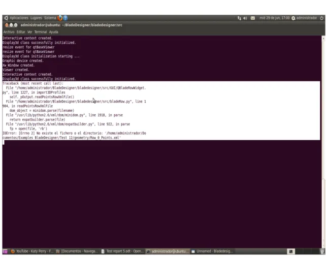
Next phase was the testing of the import function. For this test we tried to import in the test file a blade row from a given example by the developers. The import feature works over XML file format but the configuration of the file is different from the ones that BladeDesigner creates when storing the turbo machines elements. A proper importing file consists of three row of data elements: profile, hub and shroud coordinates. Each coordinate is defined in the x, y, z space in two sets of data between brackets. The first brackets contain the view in the radial direction (section) and the second brackets include the data points starting from the leading edge to the trailing edge and going back defining both suction and pressure side of the airfoil. The file has to be stored inside the geometry folder of the chosen project and with the proper name for the program to read the path correctly. If these are not correct the import progress bar gets stuck at 0% freezing the program. The shell gave us the error seen on Figure 3.3:
Figure 3.3 – Shell error when importing incorrectly named files
Once the file was stored correctly in the folder with the proper name the test was run. In order to run properly the blade row in which is imported must have the same number of active profiles as the file imported otherwise the progress bar is stuck at 50% when trying to interpolate the camber surface and the shell shows the message error from Figure 3.4:
Figure 3.4 – Shell error when importing a incorrect type of file
Also if the value of Degree or Degree U are not enough for the file being imported the program will stuck at 25% when interpolating the Nurbs surface and the shell will show the following error shown on Figure 3.5:
Figure 3.5 – Shell error for incorrect Degree values
If instead the values are too much or the teFlag option is incorrect the same error message as in Fig. 3.4 will be displayed.
All things considered if the correct options are chosen the import is done correctly and in the Plot tab of the active blade row we can see the imported blade displayed. The fact that the error messages aren't displayed in the progress bar message box indicates that in a standalone version of the program the user would have no shell to look for the error and he would just see that the program is stuck. This lack of information in the interface should be solved to help the user through the process.
The import feature doesn't write any parameter data just show the 3D plot of the imported element. So in this case if we need to build the turbo machine with the imported file we have to manually enter the profiles and blade row data to continue the process. This is not a problem or error itself but it leaves without meaning the import functions as the user will have to get the numeric data and input it anyway.
Object 2 – SCMMesher
To test the SCMMesher we had to input some values to condition the resulting mesh. First test run though was to check the stability of the interface when the user neglectfully hits the calculate button without entering any data. The result of it was that the program crashed and showed a blank interface while ceased responding to any
command. The result was repeated whenever the CGNS options were active but the CpFt coefficients were not used. The shell showed that the function was caught in a loop probably expecting data which caused the program to crash. It was necessary to kill the process and initiate again the BladeDesigner to get back control of the software. This is shown in Figure 3.6:
Figure 3.6 – Shell error when CpFt values are not entered
To test the functionality we had to use the data inputs from the scm_tutorial from the BladeDesigner documentation tutorial folder. The objective was to use the
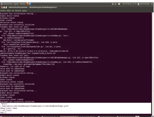
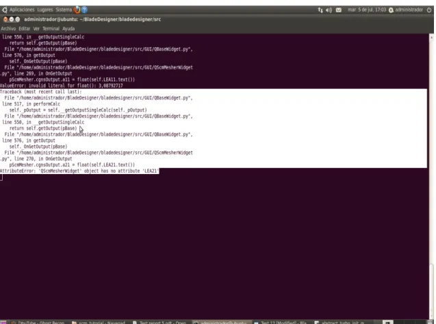
turboexample [4] turbo machine combined with the SCMMesher data examples to create meshed file to be used in CFD simulators. But when the button was clicked nothing happened. The button acted as if deactivated and no error message was displayed on screen. We knew that the function is linked to the buttons because earlier it caused a reaction in the program. So we checked the shell and Figure 3.7 was the result:
Figure 3.7 – Shell error when trying to execute the SCMMesher function
We repeated the test with different turbo machines and changing the data on the SCMMesher and the result was the same. This indicates that's there's a construction bug inside the mesher widget.
Conclusions
For this test runs we have to conclude that only half of the functionalities expected were operational. All aspects related to geometry exportation checked out fine in the testing and have been correctly integrated in the program. This options provide a full operational development of the program via geometry creation for CFD simulation use and show that the program can be used for it's final purpose.
On the other hand the 3D profile points exportation is deactivated or the button is unlinked to the function. Either way it's not a functional option of the program and the button should be removed until it's fully operational to avoid confusion for the users. At the same time the import function also checked out fine and performed it's function. However the function actually only import the 3D geometry into the Plot tab of the blade row without importing the data parameters needed to continue the turbo machine's building. If the user is forced either way to enter manually these parameters the purpose of the function is lost as it's only use is to show. This may not be a bug itself but a bad
implementation of the function which developers didn't take into account and that should be corrected if full integration into the creation process must be achieved.
As for the interface issues, it can be concluded that these functions tested in this report were included in the software without taking much care of communication between user and program as in any of the cases tested the program showed any kind of error message box or any explanation of the errors encountered. Particularly the import function create some message error in the shell which could have been easily integrated as a message box in the program to warn the user about a wrong specification of teFlag option or incorrect degree values.