Smart Grid
Reference
Architecture
Volume 1
Using
Information
and
Communication
Services
to
Support
a
Smarter
Grid
Smart
Grid
realization
is
a
utility’s
journey
through
a
series
of
architectures.
It
starts
with
the
predominant
business
‐
silo
model
with
point
‐
to
‐
point
interfaces,
to
one
best
described
as
a
systems
‐
of
‐
systems
integrated
by
shared
services
and
infrastructure.
SCE
‐
Cisco
‐
IBM
SGRA
Team
July
14,
2011
Contents
1.
Executive
Summary
...1
2.
Introduction
...2
The
Smart
Grid
Architectural
Challenge
...2
3.
Smart
Grid
Architecture
...3
Smart
Grid
Architectural
Goals
and
Principles
...3
From
a
Siloed
Architecture
to
a
Layered
Services
Architecture
...7
4.
Smart
Grid
Domains
and
Cross
Domain
Foundational
Services
...
13
5.
Smart
Grid
Reference
Architecture
Views
...
14
Application
Services
...
16
Analytics
Services
...
23
Data
Services
...
29
Control
Services
...
34
Security
Services
...
40
Communications
Services
...
44
Management
...
53
6.
Summary
...
59
Appendix
A.
System
of
Systems
Design
Patterns
...
Appendix
1
Appendix
B.
Services
Classes
Concepts
...
Appendix
11
Applications
Services
...
Appendix
11
Analytic
Services
...
Appendix
19
Data
Services
...
Appendix
29
Control
Services
...
Appendix
33
Security
Services
...
Appendix
39
Communication
Services
...
Appendix
45
Management
Services
...
Appendix
60
Structural
Model
Framework
Template
...
Appendix
65
Appendix
C.
Smart
Grid
Conceptual
Architecture
Project
(SCAP)
...
Appendix
67
Business
Requirements
...
Appendix
67
Smart
Grid
Business
Services
...
Appendix
76
Smart
Grid
Cross
‐
Domain
Foundational
Services
...
Appendix
86
Appendix
D.
Roadmap
&
Maturity
Model
...
Appendix
103
Policy
Timeline
...
Appendix
103
Pursuing
the
Smart
Grid
Vision
...
Appendix
103
Maturity
Model
...
Appendix
107
Appendix
E.
Glossary
of
Terms
...
Appendix
109
Appendix
F.
Bibliography
...
Appendix
115
Tables
Table
1
‐
Typical
Application
Specifications
...
20
Table
2
‐
Applicable
Application
Standards
...
21
Table
3
‐
Application
Technology
Recommendations
...
22
Table
4
‐
Typical
Analytics
Specifications
...
26
Table
5
‐
Recommended
Analytics
Standards
...
28
Table
6
‐
Recommended
Analytics
Technology
...
28
Table
7
‐
Typical
Data
Services
Specifications
...
31
Table
8
‐
Data
Standards
and
Technology
Recommendations
...
32
Table
9
‐
Typical
Control
Specifications
...
37
Table
10
‐
Recommended
Control
Standards
and
Technology
...
38
Table
11
‐
Advanced
Control
Elements
and
Technologies
...
39
Table
12
‐
Security
Standards
and
Technology
Recommendations
...
43
Table
13
‐
Typical
Communications
Specifications
...
47
Table
14
‐
Recommended
Communications
Standards
and
Technology
...
52
Table
15
‐
Recommended
Management
Standards
and
Technology
...
58
Table
16
–
Analytics
Capability
Maturity
Model
...
Appendix
29
Table
17
–
Market
Domain
Business
Services
...
Appendix
77
Table
18
–
Operations
Domain
Business
Services
...
Appendix
78
Table
19
–
Service
Provider
Domain
Business
Services
...
Appendix
80
Table
20
–
Generation
Domain
Business
Services
...
Appendix
81
Table
21
–
Transmission
Domain
Business
Services
...
Appendix
82
Table
22
–
Distribution
Domain
Business
Services
...
Appendix
84
Table
23
–
Customer
Domain
Business
Services
...
Appendix
86
Table
24
–
Security
Services...
Appendix
87
Table
25
–
Communications
Services
...
Appendix
89
Table
26
–
Data
Management
Services
...
Appendix
95
Table
27
‐
Glossary
...
Appendix
109
Figures
Figure
1
‐
GWAC
Interoperability
Context
Setting
Framework
Diagram
(GWAC
Stack)
...
viii
Figure
2
‐
NIST
Smart
Grid
Framework
1.0
...
ix
Figure
3
–
SCAP
Requirements
by
NIST
Domain
...
ix
Figure
4
‐
Silo
Architecture
for
EMS/SCADA
and
Metering/Billing
Functions...7
Figure
5
‐
Enterprise
Service
Bus
Architecture
...8
Figure
6
‐
Converged
Communication
Architecture
...9
Figure
7
–
System
‐
of
‐
Systems
Architecture
Based
on
Open
Standard
Services
...
10
Figure
8
‐
Smart
Grid
Conceptual
Model
...
14
Figure
9
‐
Layered
Services
Tier
View
...
15
Figure
10
‐
Application
Services
Logical
Model
...
16
Figure
11
‐
Application
Services
Structural
Model
...
19
Figure
12
‐
Analytics
Logical
Model
...
23
Figure
13
‐
Analytics
Structural
Model
...
25
Figure
14
–
Data
Services
Logical
Model
...
29
Figure
15
‐
Data
Services
Structural
Model
...
31
Figure
16
‐
Control
Services
Logical
Model
...
34
Figure
17
‐
Control
Services
Structural
Model
...
36
Figure
18
‐
Security
Logical
Model
...
40
Figure
19
‐
Security
Structural
Model
...
42
Figure
20
–
Communications
Services
Logical
Model
...
44
Figure
21
‐
Communications
Services
Structural
Model...
46
Figure
22
‐
Management
Framework
...
53
Figure
23
‐
Management
Logical
Model
...
54
Figure
24
‐
Management
Services
Structural
Model
...
56
Figure
25
‐
Silo
Architecture
...
Appendix
4
Figure
26
‐
ESB
Architecture
...
Appendix
5
Figure
27
‐
Adapter
Architecture
...
Appendix
6
Figure
28
‐
Service
‐
Centric
Architecture
...
Appendix
9
Figure
29
‐
Dis
‐
aggregation
of
a
Monolithic
System
...
Appendix
12
Figure
30
‐
Functional
Services
Organization
...
Appendix
13
Figure
31
‐
Network
Operations
planning
and
optimization
...
Appendix
14
Figure
32
‐
Smart
Grid
Analytics
Taxonomy
...
Appendix
20
Figure
33
‐
Analytics
Latency
Hierarchy
...
Appendix
26
Figure
34
‐
EIM
Framework
...
Appendix
32
Figure
35
‐
Multi
‐
Controller
/
Multi
‐
Objective
Design
Patterns
(van
Breeman,
2001)
...
Appendix
36
Figure
36
‐
Control
Center
Functional
Architecture
(IEC,
2005)
...
Appendix
37
Figure
37
‐
Hierarchical
Control
Design
Pattern
...
Appendix
39
Figure
38
‐
Security
Threats
Classification
...
Appendix
41
Figure
39
‐
Conceptual
and
Services
Layers
...
Appendix
45
Figure
40
‐
Communication
Services
Layer
Functions
...
Appendix
50
Figure
41
‐
Transport
Services
Consideration
Process
...
Appendix
51
Figure
42
‐
Conceptual
Reference
Diagram
for
Smart
Grid
Information
Networks
...
Appendix
52
Figure
43
‐
Management
Layer
Organization
...
Appendix
62
Figure
44
‐
Smart
Grid
Management
Layers
...
Appendix
64
Figure
45
‐
Structural
Model
Template
...
Appendix
66
Figure
46
‐
Communication
Services
Layer
Functions
...
Appendix
89
Figure
47
‐
California
Smart
Grid
Policy
Timeline
...
Appendix
103
Figure
48
‐
Smart
Grid
Project
Portfolios
as
a
Function
of
Maturity
...
Appendix
104
Figure
49
‐
Grid
1.0
Evolution
to
Grid
2.0
...
Appendix
106
Smart Grid Reference
Architecture
Using
Information
and
Communication
Services
to
Support
a
Smarter
Grid
About this document
This
Smart
Grid
Reference
Architecture
document
is
designed
to
address
the
challenges,
concerns
and
questions
facing
smart
grid
architects
implementing
smart
grid
solutions
for
their
utility.
As
with
any
reference
architecture,
it
aims
to
provide
a
foundation
for
utilities
in
the
development
of
their
particular
smart
grid
architectures
and
to
serve
as
a
guide
for
implementing
specific
features
designed
to
make
their
electric
grid
smarter.
The
architects
using
this
document
most
likely
work
within
utility
organizations
in
the
areas
of
operations,
generation,
transmission
and
distribution,
customer
services,
information
technology,
and
research
and
development.
Additional
audiences
may
include:
Utility executives needing clarification on developing a coherent investment roadmap to request and
secure funding to achieve their enterprise’s vision for a smarter grid.
Utilities trying to transition from the specialized, targeted architectures developed for individual
business units toward a more seamless, transparent architecture to be used across all business units.
This architecture is to meet the requirements for optimal smart grid benefits while managing the
complexities inevitably introduced by the requirements for a smarter grid.
Standards organizations (SDOs, SSOs) and policy makers needing to clearly convey a smart grid
vision with enough detail to be actionable by utilities, regardless of size. As utilities transition to the
system‐of‐systems architectural model a number of challenges and issues will arise requiring
assistance from SDOs, SSOs and state/federal policy making bodies.
Vendors providing equipment and services to electric utilities, especially those companies whose
products become more widely used.
Reference
Architecture
Wikipedia definition:
A
reference
architecture
provides
a
proven
template
solution
for
an
architecture
for
a
particular
domain.
A proven architecture is
problematic due to the
scale and immaturity of
the smart grid domain.
The reader should judge
the viability of this
document based upon the
considerable real world
experience of the SCE‐
Cisco‐IBM SGRA Team.
Foundation Frameworks
A
number
of
informative
smart
grid
documents,
white
papers,
and
frameworks
are
available
on
the
Internet.
The
following
are
especially
relevant
to
this
reference
architecture
and
worthy
of
study:
A Systems View of the Modern Grid
by
the
National
Engineering
Technology
Laboratory
(NETL,
2007)
‐
this
white
paper
inspired
many
of
the
concepts
expanded
upon
in
subsequent
publications.
It
identifies
five
primary
interdependent
elements
desirable
for
a
modern
grid
and
defines
those
concepts
including
the
seven
smart
grid
principal
characteristics
listed
in
section
2.
The GridWise® Interoperability Context‐Setting Framework
by
the
GridWise®
Architecture
Council
(GWAC,
2008)
–
a
work
that
focuses
on
the
interface
between
two
or
more
interacting
parties
and
provides
a
framework
for
discussing
the
integration
of
collaborative
processes
and
independent
automation
components.
It
identifies
eight
interoperability
categories
defined
by
the
framework
and
10
crosscutting
issues
applicable
in
every
category.
The
categories
are
tagged
as
technical,
informational
or
organizational,
and
are
stacked
according
to
their
increasing
level
of
abstraction
[
Figure
1]
.
Figure 1 ‐ GWAC Interoperability Context Setting Framework Diagram (GWAC Stack)
While
this
structure
is
not
used
to
organize
the
reference
architecture
described
in
this
document,
it
provides
the
basis
for
the
structural
models
presented
in
the
reference
architectural
views
in
section
5.
The NIST Framework and Roadmap for Smart Grid Interoperability Standards
by
the
National
Institute
for
Standards
and
Technology
(NIST,
2010)
‐
a
conceptual
model
created
to
support
the
planning
and
organization
of
the
interconnected
networks
expected
in
the
Smart
Grid.
The
NIST
approach
divided
the
Smart
Grid
into
the
seven
domains
shown
in
Figure
2
.
Figure 2 ‐ NIST Smart Grid Framework 1.0
In
2010
NIST
commissioned
the
Smart
Grid
Interoperability
Panel’s
(SGIP)
Smart
Grid
Architecture
Committee
(SGAC)
to
lead
its
Smart
Grid
Conceptual
Architecture
Project
(SCAP).
The
SCAP
working
group
took
top
‐
down
and
bottom
‐
up
approaches
to
establish
a
foundation
for
the
development
of
smart
grid
business
requirements.
The
SGAC
‘s
top
‐
down
approach
involved
a
review
of
all
major
federal
energy
legislation
signed
into
law
since
2000,
more
than
9,500
pages.
Review
of
these
documents
resulted
in
the
identification
of
400
goals.
The
bottom
‐
up
efforts
reviewed
more
than
600
use
cases
written
by
a
variety
of
industry
organizations,
including
more
than
20
systems
requirement
documents
produced
by
industry
working
groups.
The
bottom
‐
up
review
produced
more
than
8000
business
requirements
for
the
Smart
Grid.
Figure
3
illustrates
the
distribution
of
the
smart
grid
business
requirements
by
domain.
(SGIP
SGAC)
This
preliminary
work
created
400
families
of
requirements
covering
the
seven
NIST
domains.
These
high
‐
level
business
requirements
(available
on
the
NIST
website)
encompass
the
entire
Smart
Grid
from
market
to
customer
–
from
bulk
generation
to
distribution.
They
form
the
basis
of
what
the
Smart
Grid
requires
from
a
business
standpoint
and
to
meet
federal
government’s
energy
goals.
0
provides
a
list
of
the
SCAP
Business
Requirements
and
Services.
Smart Grid Reference Architecture
by
the
P2030
Working
Group
(IEEE)
‐
this
document,
expected
in
the
third
quarter
of
2011
(draft
published
in
March
2011),
will
provide
guidelines
for
smart
grid
interoperability,
including
a
discussion
of
best
practices.
The
P2030
guide
will
also
provide
a
knowledge
base
addressing
terminology,
characteristics,
functional
performance
and
evaluation
criteria,
and
the
application
of
engineering
principles
for
grid
interoperability
with
end
‐
use
applications
and
loads.
At
first
the
SCE
‐
Cisco
‐
IBM
reference
architecture
team
expressed
concern
on
the
potential
overlap
between
the
P2030
guide
and
this
document,
but
after
a
thorough
comparison
of
the
two
drafts,
the
consensus
is
that
this
reference
architecture
merely
complements
the
P2030
guide.
Whereas
the
P2030
Guide
documents
a
catalog
of
interfaces,
this
document
addresses
the
architecture
and
foundational
services
necessary
to
develop
Smart
Grid
systems,
interfaces,
and
processes.
The
alert
reader
will
notice
this
document
is
entitled
Volume
1.
It
includes
a
set
of
views
on
smart
grid
architecture
largely
written
from
the
point
of
view
of
system
integration.
It
is
expected
to
be
a
useful
companion
to
IEEE
P2030.
As
IEEE
P2030
catalogues
smart
grid
system
interfaces,
the
SGRA
Volume
1
catalogues
smart
grid
system
services.
Similarly,
the
NIST
SGCA
lists
elemental
smart
grid
functions
(unit
operations);
the
NIST
Framework
and
Roadmap
for
Smart
Grid
Interoperability
Standards
identifies
relevant
smart
grid
interface
standards;
and
the
GWAC
Interoperability
Context
‐
Setting
Framework,
as
a
companion
to
the
NIST
Framework,
provides
rigor
around
the
concept
of
interoperability.
Each
contains
more
than
described
above,
as
their
authors
will
attest,
but
these
characterizations
are
helpful
in
framing
each
document
in
the
context
of
the
entire
set.
Each
one
of
these
documents
is
a
valuable
contribution
to
the
field
of
smart
grid
architecture,
and
smart
grid
architects
are
strongly
urged
to
study
each
of
them.
However,
after
this
document
was
completed,
the
team
sensed
a
set
of
architectural
views
was
needed
to
tie
these
contributions
into
a
unified
whole
that
would
make
the
SGRA
actionable
in
both
the
near
term
and
throughout
the
general
smart
grid
utility
transformation
journey.
That
is
why
this
document
was
labeled
Volume
1,
to
be
followed
shortly
by
Volume
2.
The
Volume
2
document
will
synthesize
the
various
expositions
on
interfaces,
standards,
and
services,
as
well
as
measurement,
data
management,
control,
communications,
and
security
from
the
above
mentioned
Smart
Grid
documents
into
a
practical
consolidated
architectural
guide
representing
how
best
to
implement
smart
grids.
Volume
2
will
also
tie
together
energy
delivery
elements
of
particular
importance
as
the
smart
grid
scales
up,
resulting
in
interactions
of
increasing
complexity
with
simultaneous
impact
to
once
‐
independent
utility
tiers.
1.
Executive Summary
The Smart Grid Reference Architecture is intended as a template for Smart Grid architects to follow as
they build Smart Grid Information and Communications Technologies (ICT) architecture for their
utility, regardless of the architect’s specialty (transmission, distribution, metering, IT, communications).
The goal of this document is to accelerate the construction of a utility’s Smart Grid architecture and
implementation strategy by leveraging the reference architecture constructs contained therein.
This reference architecture recognizes the need to logically transition from the existing, largely ad hoc
nature of the typical utility grid architecture to one based on open interoperability standards, and
designed to manage complex solutions while facilitating the integration of emergent smart grid
capabilities. It explores three migrations across four transition states and takes into consideration the
many years required to develop sound recommendations for smart grid architecture.
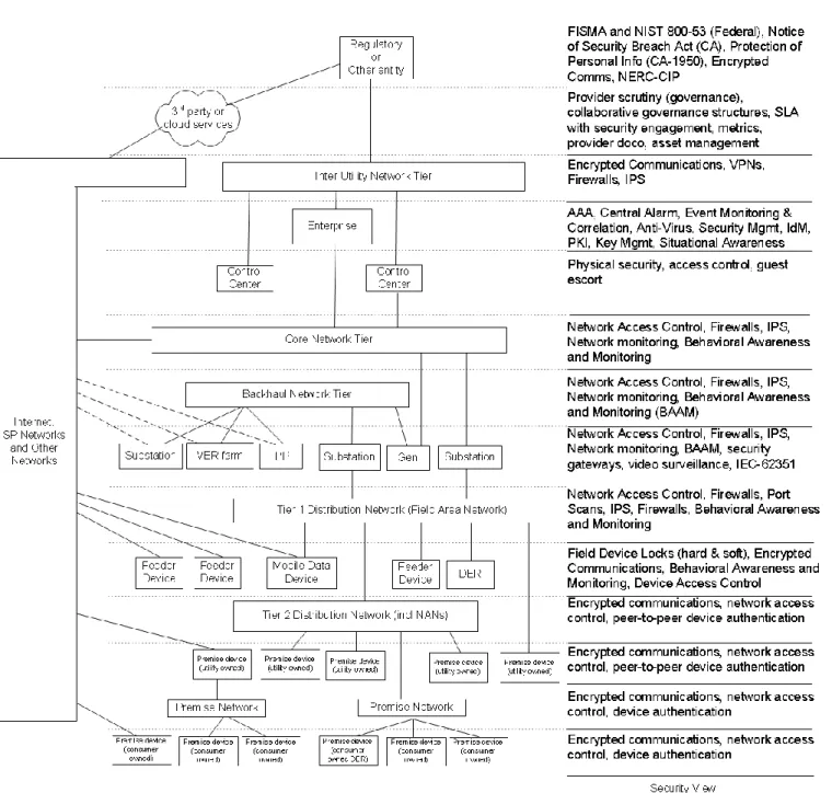
Security is an integral element of the grid ICT architecture and a multi-layered approach is advocated,
including both physical and ICT-based security mechanisms. Layering smart grid services using the
proposed system-of-systems architecture should minimize the stranded costs utilities invest in one-off
solutions. A layered service-centric architecture also minimizes the expense, configuration headaches,
and management complexity a utility faces pursuing a point-to-point interoperability architecture.
Another aspect emphasized in this reference architecture that could lead to considerable cost and time
savings for utilities are the implementation of data services and data management. Greater access to
and use of data is critical to the realization of a grid’s ability to accommodate new capabilities while
improving security, reliability and quality.
A significant portion of this reference architecture is dedicated to discussing common foundational
services and the corresponding architectural views, important for maintaining the high levels of
performance and efficiency required by a modern grid ICT. Recognizing that some services are best
centralized while others must reside primarily within grid-state aware edge components, this
discussion also explores the best central-versus-edge mix for deploying various domain components.
This Smart Grid Reference Architecture was produced by a team of architects from Southern California
Edison (SCE), Cisco Systems, and IBM. Its development spanned a period of nine months (July 2010
through March 2011) and involved a number of face-to-face team workshops and web-based meetings.
An external review by EnerNex added additional insight and content.
2.
Introduction
The Smart Grid Architectural Challenge
The January 2007 white paper,
A Systems View of the Modern Grid
, by the U. S. Department of Energy’s
(DOE) National Energy Technology Laboratory (NETL) identifies seven smart grid characteristics:
self-healing
able to motivate and engage the customer resistant to attacks
provides power quality suitable for 21st century needs accommodates all generation and storage options enables markets
optimizes assets and operates efficiently
There are a number of Smart Grid definitions, but no matter which is used, there is little dispute over
the vastness of program scopes faced by smart grid architects. Incorporating information and
communications technologies into what the National Academy of Engineering calls "the greatest
engineering achievement of the last century" (NAE, 2011) will be the one of the most complex human
endeavors ever undertaken. This robust engineering achievement must be extended to support
enhanced situational awareness (via synchrophasors), industrial-scale energy storage, distributed
(dispersed) energy resources, improved field worker effectiveness (via wireless communications and
automated asset management), remedial action scheme expansion, substation automation, volt/VAR
optimization, fine-grained demand response, distribution automation, improved power quality, power
disturbance self-healing, micro-grids, personal and fleet electric vehicles, automated metering,
premises area networks, enhanced customer energy management, power grid congestion-management,
advanced integrated command and control, transmission/distribution smart sensor deployment, very
low-latency protection communications, and not yet identified technologies that are certain to emerge
as the Smart Grid matures. All this must be accomplished as the world's largest machine, the electric
grid, continues to operate unabated, while maintaining present or improving reliability. In addition,
embedded security measures must be built concurrently to marginalize the possibility of successful
cyber and physical attacks from an ever-growing number of threats, and prevent unauthorized use of
customer personal data and energy usage information. Finally, there are demands from regulators,
political leaders, and social groups to make the grid smarter quickly, while addressing environmental
objectives and keeping electric rates low.
3.
Smart Grid Architecture
The Smart Grid architectural challenge is a daunting one. This is especially true for those within the
electric utility industry known for their conservative approach toward incorporation of ICT-based
systems to help run and manage the electric grid. Most automated grid systems in use today were built
to address narrowly targeted requirement sets. As a result, a typical utility has a plethora of purchased
and homegrown systems stitched together over the last three decades with point-to-point interfaces.
This approach is unsustainable for a utility to efficiently and effectively implement smart grid
capabilities over the next two decades. This document presents a different approach to utility system
design and integration, using newer paradigms to deal with complex and legacy system integration.
Smart Grid Architectural Goals and Principles
The next two decades will see the “Old Grid” evolve into a “Smart Grid” as legacy grid infrastructure
is merged with the latest ICT. This will put extraordinary demands on the ICT architecture; therefore,
high-level goals and principles are needed to guide the smart grid architects tasked with developing
any aspect of an organization’s grid architecture. Additionally, a highly flexible, adaptive Enterprise
Smart Grid architecture is critical for this transition to be successful. The architecture must support
existing ICT infrastructure operations and be able to keep infrastructure complexity manageable as
new smart grid capabilities are added.
How a utility defines its smart grid architecture will vary according to their organizations particular
needs. Some possible goals are:
Facilitate bridging new and emerging information and communications technology to legacy architecture over extended time periods (technology roadmap).
Manage the increasing complexity of ICT needed to support smart grid implementation. Align technology usage with the utility’s smart grid strategic objectives.
Provide guidance on how packaged solutions can support the smart grid architectural vision. Facilitate the communication of the utility’s smart grid strategy and plans across the enterprise Help sell the utility’s smart grid vision to business unit leadership, IT management, suppliers, regulatory agencies, contractors, etc.
Help stakeholders (application developers, IT managers, and end users) plan, budget, implement and use smart grid information and communication technologies.
Make the utility smart grid architecture easily accessible and transparent.
Support the interactions of processes, tools, technology and people to achieve business ICT goals.
Once a utility has defined its smart grid architecture goals it should develop a set of written principles
to provide high-level direction during architecture development. Some principles a utility may
1. Design for simplification by exploiting strategic assets Motivations:
Reduce complexity and cost
Let the enterprise’s employees focus on customer, not on internal processes Implications:
Establish single architecture control point for requests to expand the portfolio Finish what is started to enable legacy sunsets
Reduce complexity and low value work steering investment & effort to high value activities 2. Reuse process, data, and ICT assets whenever appropriate
Motivations:
Accelerate business capability delivery Reduce cost
Increase enterprise consistent use of best practice designs Increase responsiveness to regulatory requirements Implications:
Must identify, adopt and reuse process, data and ICT assets for enterprise wide use Must promote business modularity from strategy through deployment
Must direct funding to develop and adopt best practice assets 3. Use off-the-shelf rather than build solutions
Motivations:
Reduce cost and time to market Improve time to market
Implications:
Understand what off-the-shelf solutions exist and what processes they support Re-engineer the business process or model to use off-the-shelf products and services 4. Use Business Process Driven development to move toward a process-centric organization
Motivations:
ICT development will be driven by Enterprise Business Process Process will drive continual improvement across the enterprise Use business priorities to drive technology adoption
Continually improve ICT effectiveness and efficiency Facilitate cross enterprise integration
Implications:
Align enterprise processes with enterprise strategy
Close business-IT partnership with IT engaged early in the solution development process Ongoing maintenance/management of enterprise business processes
5. Base architecture on total cost of ownership (TCO) Motivations:
Provide a common approach for dealing with applications
Optimize operational manageability while making key business and technology decisions Minimize cost of complexity while making these decisions
Implications:
Elimination of low value applications at every possible opportunity
Avoid introduction of new low-value applications for short lived business requirements TCO based approach to be used for major technology decisions
6. Ensure business decisions are based on information from appropriate trusted data sources Motivations:
Achieve highest degree of integrity and validity for business decisions Minimize IT costs for managing and maintaining data
Enhance ease of doing business by eliminating manual data integration, normalization, etc Implications:
Practitioners more likely to know what trusted sources exist, and which ones to use Solution teams realize reduced cost benefits using appropriate trusted sources 7. Develop data models and a data dictionary for the entire portfolio
Motivations:
Improve operational excellence
Reduce unnecessary transformations of data and related re-work Enable meta data sharing for exchange and integration purposes Improve future system design and programming projects Improved documentation and control mechanisms Implications:
Project teams bound by data model/dictionary governance processes Close collaboration between business and IT stakeholders
Easy access to data model/dictionary given to designers and programmers 8. Master data – element created from one trusted source
Motivations:
Increased data integrity and reliability
Cost reduction for managing information and data quality Implications:
Consistently invest in, and comply with, the trusted sources architecture
Processes engineered to maintain consistent master data management and consumption 9. Only store copies of data within approved trusted sources
Motivations:
Achieve highest degree of integrity and validity for business decisions Minimize ICT costs for managing and maintaining data
Enhance ease of doing business by eliminating manual data integration, normalization, etc Implications:
Practitioners more likely to know what trusted sources exist, and which ones to use Solution teams realize reduced cost benefits using appropriate trusted sources Data currency is in line with business expectations.
10. Implement data quality plans for all business solutions Motivations:
Maximize data integrity and validity for business operations and decision making Avoid operational disruption due to data errors
Implications:
Real cost implications associated with avoidance of data quality plans Data quality easier to implement and sustain
11. Design solutions that provide measurable business performance and value Motivations:
Maximize ICT ROI
Focus design and development teams on business success goals Validate the ICT governance model
Achieve measurable performance gains Implications:
Link strategy to business case and customer requirements to metrics Enable collection, analysis and reporting of metrics, actual to plan Design generation of metric data into solutions
Establish process-level Key Performance Indicators 12. Enable applications for reuse and portability as services
Motivations:
Ability to quickly add, modify, remove or replace service functions Reduction of integration expense and partner boarding costs Facilitate the reuse of strategic applications and business functions
Enable application and function relocation for process or cost effectiveness Improve support of acquisitions and divestitures
Reduce point-to-point integration solutions Implications:
High return investment hotspots emphasized Centralized support for design enablement
Enterprise group assigned to enhance competency on standards and references Portability design based upon being agnostic on platform, location and virtualization Adoption of service modeling methodology
13. Design and test solutions to satisfy non-functional requirements Motivations:
Stabile platforms supporting the enterprise business Ensured Return On Investment
Implications:
Need to understand the target audience and expected workload of new solutions Infrastructure impact of new solutions known early in the design cycle
Infrastructure constraints considered in analysis of growth markets 14. Design solutions to make use of infrastructure common services
Motivations:
Reduction of infrastructure duplication and cost Less complexity for the end user
Improvement of system interoperability Implications:
Re-use of existing common services, reduction of new service construction Need for common services to be robust and user-friendly
From a Siloed Architecture to a Layered Services Architecture
Architectural evolution can be defined as how a typical utility implements its smart grid
transformation in stages. A white paper discussing this evolutionary process in depth can be found in
Appendix A. For the purposes of this paper the process has been divided into four stages.
Stage One: The predominate architecture of grid systems is a collection of silos.
Figure 4
is an example
of silo architecture for EMS/SCADA and metering/billing functions. Different functions (SCADA, EMS,
DMS, OMS, Billing, and Metering) use disparate information with minimal interaction.
The silo architecture worked well for utilities for decades - each silo served the needs of a business unit,
each having very different needs. Utilities operated efficiently with little integration across silos. The
silo solution, however, is not sustainable to support the Smart Grid. The number of stakeholders
needing real-time data from every silo cannot be support long-term point-to-point interfaces.
Stage Two: Some utilities have taken the next step in smart grid evolution – the integration of the back
office and applications via a common service bus, such as the enterprise service bus architecture shown
in
Figure 5
. This is often a difficult and costly process. In addition, service-bus integration requires
enforcement of standards on data models and ICT services. Without the enforcement of standards, the
service bus is simply a shared communication device with little resolution of silo weaknesses.
Stage Three: The next step towards a unified, shared infrastructure is realized by moving away from a
series of single-purpose networks to a converged communication infrastructure [
Figure 6
]. This shared
infrastructure enables as-needed data transfer from end points to consuming applications in
accordance with stated requirements (quality of service, criticality, bandwidth, latency, etc.).
Stage Four: The ultimate Smart Grid ICT architecture is converging on layered, open standard services
architecture. It provides capabilities across functional and organizational boundaries; from a
data/control center to edge devices and data consumers (applications and end users).
The system-of-system architecture shown in
Figure 7
supports the following capabilities:
Components can be added, replaced or modified without affecting the remainder of the system Components are distributable (can run on arbitrary servers)
Components communicate with each other by messages or service invocations Component interfaces are defined using standard metadata
Component interfaces are discoverable by application developers One component can replace another with the same interface
Services can be used multiple times by disparate applications or the same application.
Achieving such smart grid capabilities requires a great amount of interaction among systems. For
instance, most utilities rely on customers to report an outage; in the future, the advanced metering
infrastructure (AMI) will interact with the outage management system (OMS) to predict and confirm
outages. Once OMS confirms an outage, the distribution management system (DMS) calculates the
necessary switching steps needed to isolate the fault area and restore service in a timely manner. The
field workforce will directly interact with the OMS and DMS, responding to automatically issued work
orders and providing a detailed estimate of restoration time. Meanwhile, the customer can be notified
of the outage status in real-time via user-defined means (cell phone, web, etc.). As the capabilities of the
communication infrastructure advances, additional intelligence will be deployed closer to the
customers’ premises, allowing pro-active decisions to be made locally to avoid or minimize outages,
while informing the utility systems and operators of the locally implemented actions for potential
adjustment and optimization of energy resources.
The Smart Grid’s capabilities will need to be facilitated by an architecture that enables the connected
devices and systems to securely interact and exchange information and control. Field devices and
electrical equipment should not only publish data to help improve real-time monitoring of the electrical
grid, they will need to subscribe to other devices' information as well, allowing the devices to respond
to control signals and data requests issued by applications and systems responsible for grid monitoring
and control. This dispersion of data across the grid poses a significant challenge to utility data
management. The quality of the data is also a concern, requiring intelligent devices to be properly
configured and maintained. Device configuration control is best performed by a common management
tool tasked with component provisioning and de-provisioning. Even though the future communication
infrastructure is expected to be more robust and feature high performance communication channels,
the large amount of data, data sources and data consumers requires grid intelligence to have
decentralized and centralized aspects:
Decentralized embedded systems and applications will be responsible for analysis, filtering and taking particular actions based on the data provided by local field devices.
Centralized systems will be responsible for coordinating the decentralized systems, ensuring the overall reliability and stability of network.
With applications and systems physically dispersed into the network to lower the cost of deployment
and maintenance, each component of the Smart Grid system-of-systems will be required to satisfy four
key principles of layered services architecture:
1. Individual components can be added, replaced or modified without impact to other systems. 2. Components are distributable, communicating by messages or service invocations.
3. Interfaces between components are discoverable and leverage standard metadata 4. Component services can be easily reused by different applications.
While reusable and shared services reduce costs and minimize complexity, they also enable faster
deployment of new applications. This will be crucial for the utility to efficiently adapt to evolving
regulatory mandates.
To transition from a Stage 1 silo architecture, or a Stage 2 partially integrated architecture to a Stage 3
or Stage 4 layered services architecture, the utility must define and plan for strategic investments in
modernizing its infrastructure and systems. To be successful, each planned investment must be
reviewed and assessed from an enterprise standpoint to ensure investments help the organization
transition toward the future Smart Grid Architecture. Adoption of shared services, standards and a
unified infrastructure need to be understood as intrinsic requirements for each planned investment.
A transition plan some companies have adopted is to first move from a siloed architecture to
middleware integration architecture. This is followed by a gradual migration to an open-standards
based architecture, incrementally developing and adopting standards and common services. Each
increment helps move the enterprise toward the vision of this Smart Grid Reference Architecture. The
timing of the transitions is often documented by a smart grid roadmap. Appendix D presents one
technique for constructing a roadmap. It also provides a brief discussion on the Smart Grid Maturity
Model (SGMM) sponsored by Carnegie Mellon University.
The smart grid architect should apply the system-of-systems architecture patterns described to first
develop use cases and a comprehensive set of requirements. These can then be used to develop the
shared services and target physical architectures needed to support the desired capabilities across the
utility’s smart grid.
4.
Smart Grid Domains
andCross Domain Foundational Services
Seven domains comprise the conceptual model described in
NIST Framework and Roadmap for Smart Grid
Interoperability Standards, Release 1.0
(NIST, 2010). A smart grid has inherent power flow and grid state
complexity embedded primarily within this model’s Operations domain. This SGRA recommends two
additional domains should an architect wish to explicitly address these complexities. In addition, the
SGRA supports the concept of foundation-level services used by multiple domains.
The NIST smart grid conceptual model domains are:
Customer: the functional needs within the customers’ premises, including the ability to generate, store, monitor and control the electricity usage of customers (both residential and commercial). Market: the functional and operational need for operators and participants in the electricity market. This is where efficient matching of energy production and consumption is performed.
ServiceProvider: the functional needs of organizations offering or leveraging utility services. These include power producers, distributors, regulatory agencies, banks, credit bureaus, etc.
Operations:managers of electricity movement, responsible for the smooth operation of the grid BulkGeneration: the needs of power generation entities producing more than 300 megawatts. Transmission: the applications and tools to deliver bulk electricity over long distances, such as a Regional Transmission Operator or Independent System Operator (RTO/ISO).
Distribution: often considered the primary focus of smart grid changes, offers all the required functional services to electricity distributors to and from customers, as well as the services to manage distributed energy resources, including energy storage and plug-in electric vehicles.
Supplementing the NIST-defined domains, the following are potential expansions to the architect’s
smart grid conceptual model:
Balance – required for the dispatch of distributed energy resources and demand response due to their roles in balancing supply vs. demand on the grid; increasingly data interaction between the utility, the consumer and the balance authority will be needed in the Smart Grid environment. Interchange – the visibility onto grid state required to address increased power flow complexity, placing requirements on smart grid systems for data communications and management.
Cross domain foundational services
are those that two or more domains rely upon and therefore need to
be interoperable across domains. For example, a system having one form of encryption in one domain
and a different one in another will lead to problems when the two exchange information, thus causing
additional work to correct the problem in the final implementation. This could be avoided by a single
encryption method used by all systems as a cross domain foundational service.
Cross domain services are broken down into six groups: Analytics, Data, Control, Security,
Communication, and Management. Discussions on each service group can be found in Appendix B.
Architects and others interested are encouraged to study this appendix for more detail.
5.
Smart Grid Reference Architecture Views
The comprehensive, end-to-end, high-level architecture needed to support the utility business domains
and common enabling services discussed in Section 4, uses a model that assumes a service-oriented
governance process exists supporting the intrinsic characteristics of layered services architecture. The
model’s seven business domains are each logical groupings of business capabilities providing related
business functions while requiring similar skills and expertise. These match the domains identified by
NIST in Special Publication 1108,
NIST Framework and Roadmap for Smart Grid Interoperability Standards,
Release 1.0
(NIST, 2010).
These functional areas form the basis for defining the boundaries of ICT capabilities and systems, and
provide a means to classify components and services. Common enabling services provide a variety of
services for systems and subsystems to accomplish business functions. Governance provides a
framework to define the relationships and processes used to direct and control grid activities, as well as
the actions, authority and metrics used to realize business benefits while balancing risk versus reward.
The left side of
Figure 8
shows the seven NIST utility domains as distinct logical groupings of common
capabilities. A utility may elect to combine some domains (i.e. distribution and transmission) and plan
a single logical infrastructure to support the Smart Grid. In addition, utilities opting for interactions of
Smart Grid elements with the Balance and Interchange domains will need to extend this model.
Figure 8 - Smart Grid Conceptual Model
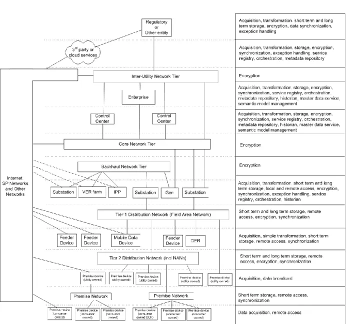
The top of
Figure 9
names five smart grid end-state architecture tiers (user/device, channel,
back) through the various tiers, each with layered service groups or capabilities. The large box at the
bottom of the figure (spanning the three right tiers) represents the cross domain foundational services
discussed in section 4 above.
Figure 9 - Layered Services Tier View
Each services group discussed in the following subsections provides a:
Logical architecture diagram Structural architecture diagram
Table of typical architectural specifications for the service group Table of relevant standards for the service group
Application Services
Smart grid applications services provide functionalities for the presentation tier, the services tier, and a
mechanism to integrate various applications through the integration tier as depicted in
Figure 9
.
Applications consume services to present secure, timely, relevant, and understandable information in
response to a validated stakeholder request.
Applications Services Logical Model
The
Application Services Logical Model
[
Figure 10
] is made up of three views, (1) application component,
(2) application services stack and (3) application